Demonstrating Multi-bit Magnetic Memory in the Fe8 High Spin Molecule by Muon Spin Rotation.
Abstract
We developed a method to detect the quantum nature of high spin molecules using muon spin rotation, and a three-step field cycle ending always with the same field. We use this method to demonstrate that the Fe8 molecule can remember 6 (possibly 8) different histories (bits). A wide range of fields can be used to write a particular bit, and the information is stored in discrete states. Therefore, Fe8 can be used as a model compound for Multi-bit Magnetic Memory. Our experiment also paves the way for magnetic quantum tunneling detection in films.
Immediately after the discovery of single molecular magnets it was suggested that they could be used as multi-bit magnetic memory CaneschiJMMM99 . However, this has never been demonstrated in the laboratory. For such a demonstration the molecules must be subjected to several different magnetic treatments (histories), which can then be clearly distinguished by a measurement in a unique external condition. Other requirements from a good magnetic memory is that, on the one hand a wide range of field will be remembered in exactly the same way, and on the other hand, the stored information will be discrete and hence very clearly distinguishable. Here we demonstrate, using muon spin rotation (SR) and a three-step field cycle ending always with the same field, that the Fe8 molecule can remember 6 (possibly 8) different histories and could serve as a model compound for multi-bit magnetic memory.
Fe8 is an abbreviation for [(C6H15N3)6Fe8O2(OH)12]Br7(H2O)Br8H2O, which was first synthesized in 1984 WieghardtACIEE84 . The magnetically active part of this molecule is constructed from 8 iron (III) ions, each having spin . In the ground state, 6 individual spins, out of the 8, point parallel to each other, while the other 2 spins are directed anti-parallel to the first 6 PontillonJACS99 ; DelfsIC93 . As a result, Fe8 molecules have a giant electronic spin of . In addition, the giant spins reside on a lattice, and the interaction between them are small compared to the intramolecular interactions FurukawaPRB02 . Due to the anisotropy of the crystal field, the main terms of their Hamiltonian in the presence of an external magnetic field in the direction is , where K SangregorioPRL97 ; BarraEL96 , is the spectroscopic splitting factor, and is Bohr magneton. The most outstanding feature of this Hamiltonian is that, at certain “matching” fields, given by Oe where is an integer, states with positive and negative values have identical energies DelfsIC93 ; BarraEL96 . As a result, at the matching fields tunnelling can take place between spin states of opposite polarization. Similarly, when is very different from these transitions are suppressed. This property can be utilized to prepare the system in a number of different spin configurations, which are stable for a relatively long time, by cycling an external magnetic field, even though at the end of the cycle the field returns to the same value, which is nearly zero field.
For the preparation of various spin states we start by applying a strong negative (or positive) magnetic field of -10 kOe (10 kOe) parallel to the easy axis for 10 minutes to polarize the Fe8 molecules. In such a strong field all the spins are in their () state. The field is then swept to an intermediate positive (negative) value , at a rate of 41 kOe/sec, crossing a matching field in the process, and, as a consequence, populating states with positive (negative) . Finally, the field is swept back to +50 Oe (again crossing several matching fields), where the changes in the sample magnetization as a function of are determined.
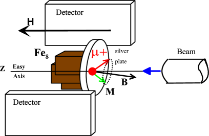
The determination of the magnetization was done using the muon spin rotation [SR] technique BrewerMS98 and was performed at the low temperature facility (LTF) of the Paul Scherrer Institute, Switzerland. This technique is used to study the magnetic properties of materials through direct measurement of the time dependence of a positive muon () polarization, and it is sensitive to field changes on the order of G. The essence of the SR measurement is that the muon spin rotates around the axis of the internal field, and decay positrons are emitted asymmetrically with respect to the muon spin direction. Positron detectors are placed perpendicular to , the direction of the external field and beam, as depicted in fig. 1. In this figure one of the possible directions of the magnetization and the internal field , around which the muon spin rotates, is shown. The initial polarization of the muons was set to be 45o relative to . The data from the two counters are used to reconstruct the asymmetry of the muon decay as a function of time from the moment the muon arrives. In our experimental configuration, this asymmetry is proportional to the muon spin polarization in the direction perpendicular to . Monitoring the muon polarization rotation frequency for various allows us to detect clearly the different spin configurations. Preliminary data using this method was presented in Ref. SalmanPhysicaB03 .
Our SR measurements are performed on a few Fe8 single crystals, glued on a small silver plate (0.5mm thick) sample holder using GE varnish, and aligned so that their direction (easy axis UedaJPSJ01 ) is parallel to the muon beam direction and external field directions. The Fe8 single crystals were positioned in two different configurations. In the first configuration (indirect) the plate faced the beam, meaning the muons hit the plate and are at best 0.5 mm away from the crystals. This configuration is shown in Fig. 1. In the second configuration (direct) the Fe8 faced the beam, meaning most of the muons hit the Fe8 but some miss the crystals and land on the silver plate or GE varnish very close to the crystals. We tested both configurations since it was not clear, a priori, which one would yield better results. For each configuration a calibration test was performed (no-Fe8) in which the Fe8 was removed from the holder and the muons stopped in the silver plate. This test was necessary because a superconducting magnet, like the one used in the experiment, could have trapped flux, leading to a slightly different measured field for different intermediate fields, even though the magnet power supply was set to produce Oe at the end of each field cycle. In both configurations the samples were cooled down to a temperature of 40-100 mK in order to minimize the thermal activation effects (the tunnelling process dominates below 360mK SangregorioPRL97 ; OhmLTP98 ).
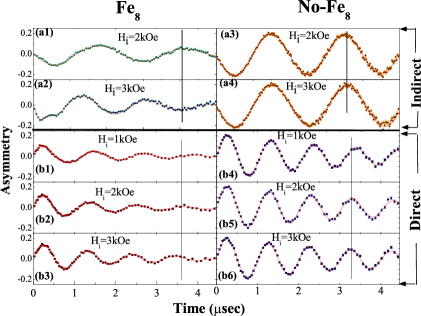
In Fig. 2 we present the asymmetry as a function of time for both direct and indirect configurations, for different intermediate fields , and the calibration. The results of the indirect experiments are depicted in the four top panels (a1-a4) while the results of the direct experiment are shown on the bottom six panels (b1-b6). All panels on the left side are measurements with the Fe8 and on the right are calibration measurements of the empty silver sample holder. The most noticeable variation in Fig. 2 is the difference in amplitude between the experiment with the Fe8 and the calibration experiment with an empty holder. This is due to quick depolarization outside the SR time window of some of the muons stopping at sites with strong magnetic fields. Due to this depolarization we were sceptic about the success of the direct experiment. This fast depolarization is discussed further below. A more important but subtle change in the data is the difference in the muon asymmetry between runs with the Fe8, panels (a1) to (a2) and (b1) to (b3). The different intermediate fields cause different precession frequencies of the muon spin. This is emphasized in the direct configuration by the vertical solid line passing through the fourth maximum of the kOe run [panel b2]. For comparison, the fourth maximum of the kOe and 3 kOe [panels (b1) and (b3)] are a quarter wave to the left and to the right of this line, respectively. In contrast, the situation in the calibration case, panels (b4) to (b6), is different. There is no noticeable difference in the muon asymmetry between the intermediate fields kOe and 3 kOe [panels (b5) and (b6)], and only a small difference between the kOe and kOe measurements [panels (b4) and (b5))]. Therefore most of the frequency shift is due to the Fe8 molecules. A similar demonstration is presented by the vertical solid line in the indirect experiment. In this measurement two frequencies showed up in the muon precession when the Fe8 is in use. The reason for having two frequencies is not yet clear to us. It should be pointed out that the difference in muon precession frequency between the direct and indirect experiments in the No-Fe8 case is due to different plate position with respect to the center of the magnet.
The data are analyzed by fitting the asymmetry of all measurements with a function of the form:
where is the muon frequency, is the magnetic field experienced by the muon, MHz/T is the muon gyromagnetic ratio, and is the decay coefficient. The subscript () stands for high (low) frequency and high (low) relaxation. In the direct experiment a single component oscillating function was sufficient for the fit.
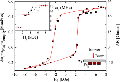
In Fig. 3 we present the indirect experimental results. In this figure, the low frequency shift between the calibration test and the experiment with the sample is plotted as a function of the intermediate field and the solid line is a guide to the eye. This solid line forms an unusual kind of hysteresis loop despite the fact that the measurements were always done in the same conditions. The shift saturates at high intermediate fields, and it changes drastically in the regime of kOe. In addition, there is a big difference between of intermediate fields with opposite sign, namely, the hysteresis loop is not symmetric around zero shift. Some of the high frequencies as a function of the intermediate fields are shown in the inset of Fig. 3. Despite the noisy data, there is some indication of steps, which are emphasized by the horizontal lines.
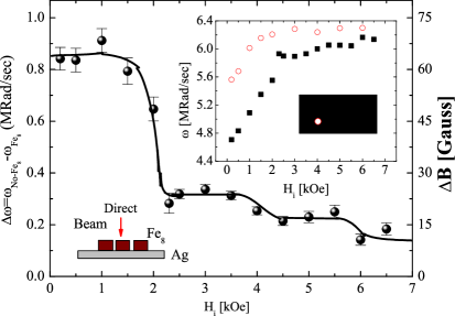
A better frequency resolution was achieved in the direct experiment presented in Fig. 4 where the frequency shift between the calibration test and the sample measurements is presented. Again, the solid line is a guide to the eye. Since only one oscillating component similar to was required for the fit in this case, has no subscript. The shift is the largest at low and decreases sharply when grows toward the first matching field of 2.2 kOe. Upon further increase of , stays flat until a second decrease occurs slightly above 4 kOe. This situation seems to repeat itself above 6 kOe as well. We did not apply negative in the direct experiment.
It is important to note that these measurements have been repeated more than once in order to check whether the results are reproducible. Performing the same field cycle twice always gave exactly the same muon behavior in both sample and calibration measurements. This provides reassurance that the frequency shift is reproducible. Also, in other magnetization experiments WernsdorferS99 the biggest change in the magnetic moment is found at the second matching field and not in the first one . The fact that we detect the biggest shift at in both of the experimental configurations (Fig. 3 and Fig. 4) could be explained by non-perfect alignment of the Fe8 mosaic resulting in a field perpendicular to . An alternative explanation is avalanche of the magnetization, which are known to occur in large crystals. In both cases most of the magnetization flips at the leaving little magnetization to vary at a higher matching field, and reduced sensitivity of the shift to higher . However, in principle, once films become available, avalanches might not be a problem and one might be able to tune the height of the jumps by a transverse field, leading to the different steps having equal sensitivity.
The dependence of on is the main finding in this work. First of all, it reveals once again the quantum nature of these crystals, since the period of seems to agree with the kOe period found by other methods WernsdorferS99 . Secondly, and more importantly, it shows that Fe8 molecules can “remember” which intermediate field was visited with 3 clear plateaus (perhaps 4) and also can distinguish between positive and negative , giving all together 6 (possibly 8) different memory bits. In addition, a field range of 2 kOe can be used to write a particular bit, but the stored information is discrete. Finally, this memory lasts at least on the time scale of the SR measurement (1/2 hour). In fact, we have preliminary data showing that this memory lasts at least for several hours (not shown). It is this recollection of , and the fact that many final frequencies can be prepared, which warrants Fe8 molecules the candidacy for a multi-bit magnetic memory model compound.
Next, we address the question of the decrease in asymmetry between the sample and holder measurements. We noticed, by measuring samples of increasing size, that the amplitude of the muon rotation decreased. This lead us to a speculation that muons that enter the sample relax immediately, and we are actually observing only the muon that missed the sample and landed in the sample holder or GE varnish. Since Fe8 is a ferromagnet, the field it creates outside the crystal depends on the average polarization of the molecules, and it is this average that we detect.
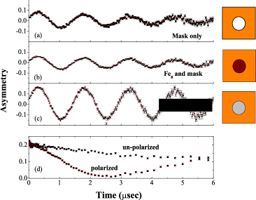
In order to check this hypothesis we measured the asymmetry of three different samples: (I) a mask made of hematite and glue with a hole in its centre, using a veto counter (muons that missed the mask are not counted). In this case we found asymmetry (see Fig. 5a); (II) the same sample as in (I) but having the hole covered with Fe8 powder (see Fig. 5b). In this case we found ; (III) the same as in (I) but having the hole covered with silver (see Fig. 5c). In this case . From (I) and (II) we can write
where is the asymmetry from Fe8, and and are the probabilities of landing in the mask or hole respectively. From (III) we get
since in silver . The solution of these equations, together with , gives . When considering the fact that in our shift experiment the Fe8 crystals are also covered with a thin layer of GE varnish, is consistent with zero. We therefore conclude that muons in Fe8 relax immediately as they do in hematite.
Another indication to support this conclusion is shown in Fig. 5d. Here we present the muon longitudinal polarization (in the beam directions) in zero field before and after the Fe8 electronic spins have been polarized. In the unpolarized state the muon relaxation is weak. Therefore, all muons experience a weak field. This signal cannot come from muons inside the sample where they interact with their neighboring spins and the average of the field magnitude is not zero. This indicates that the signal is from muons outside the sample. Indeed, when the Fe8 spins are polarized the muon relaxation increases, since the field strength outside the sample increases.
This experiment indicates that in our shift measurement we detect muons that are stopped either in the thin layer of GE varnish covering the crystals or on the silver plate in between crystals. These muons will experience an averaged field from many molecules.
Finally, molecular clusters have been widely investigated as a model for magnetism at the nano-scale, especially for quantum tunnelling of the magnetization (QTM), since the memory stored in a single molecule can be lost via QTM without thermal assistance. In parallel, a considerable effort is being made to produce films of molecular magnets CaroCM00 ; CaroCVD02 ; CasellasSP03 . Once this goal is achieved it will be essential to probe their magnetization. This is not a trivial matter since many experimental techniques that probe bulk materials are not applicable to films. Our work presents one way to probe QTM in this situation since the recent development of the slow muon apparatuses at PSI allow us to stop muon in films of various thicknesses BakuleCP04 . We learned here that it would be best to grow the films on a non magnetic substrate and to implant the muons in the substrate rather than in the film. The quantum nature of the films could then be investigated using the three step field cycle.
This work was performed at the Swiss Muon Source, Paul Scherrer Institute, Villigen, Switzerland, and supported by the Swiss Federal Office for Education and Science (BBW). We are grateful to the machine and instrument groups whose outstanding efforts have made these experiments possible. It was also supported by Israeli Science foundation under the Bikora program.
References
- (1) A. Caneschi, T. Ohm, JMMM 200 182-201 (1999).
- (2) K. Wieghardt, K. Pohl ,I. Jibril and G. Huttner , Angew. Chem. Int. Ed. Engl., 23 (1984) 77.
- (3) Yves Pontillon et al., J. Am. Chem. Soc. 121, 5342 (1999).
- (4) C. Delfs et al., Inorg. Chem. 32, 3099 (1993).
- (5) N. V. Prokof’ev and P. C. E. Stamp, Phys. Rev. Lett. 80, 5794 (1998); Y. Furukawa et al., Physical Review B 64, 094439 (2001).
- (6) C. Sangregorio, T. Ohm, C. Paulsen, R. Sessoli & D. Gatteschi. Phys. Rev. Lett. 78, 4645 (1997).
- (7) A.-L. Barra, P. Debrunner A, D. Gatteschi, Ch. E. Schulz, R. Sessoli. Europhys. Lett., 35 (2), 133 (1996).
- (8) M. Ueda, S. Maegawa, H. Miyasaka & S. Kitagawa, J. Phys. Soc. Jpn. 70, 3084, (2001).
- (9) J. H. Brewer, R. Cywinski, ”Muon Science – Muons in Physics, Chemistry and Materials” edited by S. L. Lee, S. H. Kilcoyne and R. Cywinski, (1998).
- (10) Z. Salman, A. Keren, S. Megeawa, M. Ueda, O. Shafir, B. Barbara, C. Baines, Physica B 326, 480 (2003).
- (11) T. Ohm, C. Sangregorio, C. Paulsen, J. Low Temp. Phys. 113, 1141 (1998).
- (12) W. Wernsdorfer, R. Sessoli, Science 284, 133 (1999), M. Ueda, S. Maegawa, and S. Kitagawa, Phys. Rev. B 66, 073309 (2002).
- (13) D. de Caro, M. Basso-Bert, J. Sakah, H. Casellas, J.-P. Legros, L. Valade, P. Cassoux, Chemistry of Materials 12, 587 (2000).
- (14) D. de Caro, L. Valade, P. Cassoux, Chemical Vapor Deposition 8, 145 (2002).
- (15) H. Casellas, L. Valade, D. de Caro, P. Cassoux, F. Villain, D. Gatteschi, Society Proceedings Volumes 8, 1001 (2003).
- (16) P. Bakule E. Morenzoni, Contemporary Physics 45, 203 (2004).