Antiferromagnetic Metal Spintronics
Abstract
Spintronics in ferromagnetic metals is built on a complementary set of phenomena in which magnetic configurations influence transport coefficients and transport currents alter magnetic configurations. In this Letter we propose that corresponding effects occur in circuits containing antiferromagnetic metals. The critical current for switching can be smaller in the antiferromagnetic case because of the absence of shape anisotropy and because spin torques act through the entire volume of an antiferromagnet. Our findings suggest that current-induced order parameter dynamics can be used to coarsen the microstructure of antiferromagnetic thin films.
Introduction — Spintronics in ferromagnetic metalsReview is based on one hand on the dependence of resistance on magnetic microstructure GMRrefs , and on the other hand on the ability to alter magnetic microstructures with transport currents Slon ; Berger ; Tsoi1 ; Tsoi2 ; Sun ; SMT-exp ; Chien ; MSU . These effects are often largest and most robust in circuits containing ferromagnetic nanoparticles that have a spatial extent smaller than a domain wall width and therefore largely coherent magnetization dynamics. In this Letter we point out that similar effects occur in circuits containing antiferromagnetic metals. The systems that we have in mind are antiferromagnetic transition metals similar to CrFawcettI and its alloysFawcettII or the rock salt structure intermetallics ExchangeBias used as exchange bias materials which are well described by time-dependent mean-field-theory in its density-functional theoryGunnarrson setting.
Our proposal that currents can alter the micromagnetic state of an antiferromagnet may seem surprising since spin-torque effects in ferromagnets TransferTheory are usually discussed in terms of conservation of total spin, a quantity that is not related to the staggered moment order parameter of an antiferromagnet. Our arguments are based on a microscopic picture of spin-torquesnunez2004 in which they are viewed as a consequence of changes in the exchange-correlation effective magnetic fields experienced by all quasiparticles in the transport steady state. A spin torque that drives the staggered-moment orientation must also be staggered, and will be producednunez2004 by the exchange potential due to an unstaggered transport electron spin-density in the plane perpendicular to . The required alteration in torque is produced by the alternating moment orientations in the antiferromagnet rather than the transport electron exchange field. As we now explain the transverse spin-densities necessary for a staggered torque occur generically in circuits containing antiferromagnetic elements.
The key observations behind our theory concern the scattering properties of a single channel containing non-collinear antiferromagnetic elements with a staggered exchange field that varies periodically along the channel and is commensurate with an underlying lattice that has inversion symmetry. For an antiferromagnetic element that is invariant under simultaneous spatial and staggered moment inversion it follows from standard one-dimensional scattering theory Melo considerations that transmission through an individual antiferromagnetic element is spin-independent, and that the spin-dependent reflection amplitude from the antiferromagnet or any period thereof has the form , where is the order parameter orientation and are the Pauli spin matrices; and are proportional to sums and differences of reflection amplitudes for incident spins oriented along and opposite to the staggered moment. The reflection amplitude for a spinors incident from opposite sides differ by changing the sign of and the transmission amplitudes are identical. It then follows from composition rules for transmission and reflection amplitudes in a compound circuit containing paramagnetic source and drain electrodes and two antiferromagnetic elements with staggered moment orientations and separated by a paramagnetic spacer (see Fig. 1) that the transport electron spin-density in the direction is periodic in the antiferromagnets. (We define the direction of to be the direction of the local moment opposite the spacer.) The spin-torques that appear in this type of circuit therefore act through the entire volume of each antiferromagnet.
A proof of this property will be presented elsewhere. Here we illustrate the potential consequences of this property by using non-equilibrium Greens function techniques to evaluate antiferromagnetic giant magnetoresistance (AGMR) effects and layer-dependent spin-torques in model two-dimensional circuits containing paramagnetic and antiferromagnetic elements. We focus on the most favorable case in which the antiferromagnet has a single spin-density-wave state with in the current direction. In the following we first explain the model system that we study and the non-equilibrium Greens function calculation that we use to evaluate magnetoresistance and spin-torque effects. We conclude that under favorable circumstances, both effects can be as large as the ones that occur in ferromagnets. We then estimate typical critical current for switching an antiferromagnet. Finally, we discuss some of the challenges that stand in the way of realizing these effects experimentally.
Antiferromagnetic giant magnetoresistance — We start by analyzing the simplified two-dimensional lattice model of an antiferromagnetic heterostructure characterized by near-neighbor hopping, transverse translational invariance, and spin-dependent on-site energies, that is illustrated in Fig. 1:
| (1) | |||||
Here, denotes the transverse wave number, the hopping amplitude and the transverse kinetic energy. The second term in Eq. (1) describes the exchange coupling of electrons to antiferromagnetically ordered local moments that alternate in each antiferromagnet. In the paramagnetic regions of these model systems . The on-site energies are allowed to change across a heterojunction.

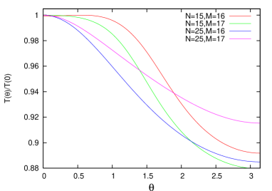
We use the non-equilibrium Greens function formalism to describe the transport of quasiparticles across the magnetic heterostructure. The essential physical properties of the system are encoded in the real time Greens function caroli1972 ; dattabook , defined by the ensemble average, , from which the (spin) current and (spin) density can be evaluated. To determine the model’s AGMR effect, we calculate the transmission coefficient as a function of the angle between orientations on opposite sides of the spacer. In Fig. 2 the transmission coefficient is shown for specific values of the number of layers and , in the first and second antiferromagnet. The AGMR effect can be traced to the interference between spin-current carrying electron spinors reflected by the facing layers. (This is also the origin of spin transfer.) For the model we study the AGMR depends on the orientation of the layers opposite the spacer in the usual way, i.e. the resistance is highest for and lowest for . Also, we find that the AGMR ratio, defined as the absolute difference between the maximum and minimum value of the transmission coefficient normalized to the minimum, saturates as a function of the length of the antiferromagnets.
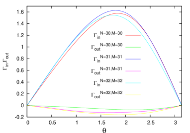
Current-driven switching of an antiferromagnet — To address the possibility of current-induced switching of an antiferromagnet we evaluate spin transfer torques in the second antiferromagnet. The spin transfer torque originates from the contribution made by transport electrons to the exchange-correlation effective magnetic field and is givennunez2004 by , where is the nonequilibrium expectation value of the quasiparticle spin. We distinguish the spin-torque component in the plane spanned by and and the component out of this plane. In Fig. 3 we show the in-plane and out-of-plane transport-induced spin torques. As anticipated the in-plane spin transfer torque in this model is exactly staggered and is therefore extremely effective in driving order-parameter dynamics. We have checked numerically that staggered in-plane spin-transfer torques that do not decay also occur in continuum toy models of an antiferromagnet with piece-wise constant and sinusoidal exchange fields. These persistent spin torques are a generic property of antiferromagnetic circuits related to the absence of spin-splitting in the Bloch bands. The staggered in-plane spin-transfer is produced by an out-of-plane spin density that is exactly constant in our lattice model antiferromagnet and exactly periodic in a continuum model antiferromagnet.

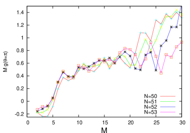
If the exchange-interactions that stabilize the antiferromagnetic state are very strong, the magnetization dynamics of each antiferromagnetic element will be coherent and respond only to the staggered component of each spin-torque. In Fig. 4 we show the total staggered torque acting on the downstream antiferromagnet, as a function of the angle . Clearly, the out-of-plane component of the torque is small compared to the in-plane component. Fig. 5 shows the derivative of the spin transfer torque per unit current with respect to , which we denote , at . As we will see, the critical current for reversal is inversely proportional to this quantity.
Having demonstrated the presence of spin transfer torques in a heterostructure containing two antiferromagnetic elements, we estimate the critical current for switching the second antiferromagnet assuming that the first is pinned. To illustrate our ideas, we use the crystalline anisotropy energy density for Cr FawcettI ; fenton1978 , given by
| (2) |
where is a unit vector in the direction of the staggered moment. The first term changes sign at the spin flop transition FawcettI , and forces the staggered moment to be either parallel or perpendicular to the ordering vector . At room temperature , and for the geometry in Fig. 1 we have leading to the first term in Eq. (2). The term involving describes cubic anisotropy in the plane perpendicular to .
As we have seen, the spin transfer torques act cooperatively throughout the entire antiferromagnet. Therefore, we can focus our description on one ferromagnetic layer within the antiferromagnet, since the antiferromagnet ordering will be preserved as the antiferromagnet switches. Within this approach, the dynamics of the staggered moment of the second antiferromagnet is analogous to the ferromagnetic case, and its equation of motion reads
| (3) | |||||
Here, denotes the gyromagnetic ratio, and denotes the saturated staggered moment density, where nm denotes the lattice constant of Cr. The term involving , with the current density and the electron charge, describes the in-plane spin transfer torque. We neglect the out-of-plane component because, as we have seen, it averages to a small value. Moreover, the out-of-plane component of the spin torque competes with the anisotropy, whereas the in-plane component competes with the damping term. For this reason it turns out that, even in ferromagnets, the in-plane component of the spin torque is most important in determining the critical current for current-driven switching. The last term in Eq. (3) describes the usual Gilbert damping, with a dimensionless damping constant for which we take the typical value fenton1978 . The anisotropy constants are given by J m-3 and J m-3 fenton1978 .
A linear stability analysis of Eq. (3) shows that for the optimal situation , the fixed point becomes unstable if
| (4) |
where the value for is found to be .
This critical current is smaller than the typical value for switching an ferromagnet primarily because the spin transfer torques act cooperatively throughout the entire antiferromagnet and also because of the absence of shape anisotropy. Using the model of Eq. (3) we also find that depending on the applied current, the staggered moment can relax to stable fixed points at or completely reverse its direction.
Discussion and conclusions — The calculations we have performed are in the ballistic regime, and we expect the AGMR and spin transfer torque effect to occur only in sufficiently clean samples. Since both effects rely on interferences, however, we do not expect that disorder will make it impossible to realize the effect in typical nanoscale layered systems. Initial experimental explorations of this effect might be most easily interpreted in clean epitaxially grown materials. The complicated antiferromagnetic domain structure, known to play a complex role in exchange biasing materials nogues1999 , might cause AGMR and antiferromagnetic spin transfer to be smaller than expected on the basis of our calculation. We point out that it might be possible to use the effects discussed here to coarsen the domain structure of antiferromagnetic thin films. We therefore expect that the metallic materials used for exchange biasing are generally a good starting point in searching for materials displaying these antiferromagnetic spintronics phenomena. The materials combinations that will exhibit the effects we have in mind most strongly depend on a large variety of considerations and can be identified by a combination of experimental and theoretical work which follows in the footsteps of the successful ferromagnetic metals materials research. Finally we remark that related effects occur in hybrid circuits containing both antiferromagnetic and ferromagnetic elements.
In conclusion we propose that the experimental and theoretical study of the influence of current on microstructure in circuits containing antiferromagnetic elements will reveal interesting new physics only partly anticipated in this Letter, and that microstructure changes can be sensed by resistance changes. It is a pleasure to thank Olle Heinonen, Chris Palmstrom, and Maxim Tsoi for helpful remarks. This work was supported by the National Science Foundation under grants DMR-0115947 and DMR-0210383, by a grant from Seagate Corporation, and by the Welch Foundation.
References
- (1) S.A. Wolf et al., Science 294, 1488 (2001).
- (2) M. Baibich et al., Phys. Rev. Lett. 61, 2472 (1988); J. Barnas et al., Phys. Rev. B42, 8110 (1990).
- (3) J.C. Slonczewski, J. Magn. Magn. Mater. 159, L1 (1996).
- (4) L. Berger, Phys. Rev. B 54, 9353 (1996).
- (5) M. Tsoi et al., Phys. Rev. Lett. 80, 4281 (1998); M. Tsoi et al., Nature 406, 46 (2000);
- (6) M. Tsoi et al., Phys. Rev. Lett. 89, 246803 (2002).
- (7) J.Z. Sun, J. Magn. Magn. Mater. 202, 157 (1999).
- (8) E. B. Myers et al., Science 285, 867 (1999); J.A. Katine et al., Phys. Rev. Lett. 84, 4212 (2000); E.B. Myers, et al., Phys. Rev. Lett. 89, 196801 (2002); S.I. Kiselev, et al., Nature 425, 380 (2003); W.H. Rippard, M.R. Pufall, and T.J. Silva, Appl. Phys. Lett. 82, 1260 (2003); F. B. Mancoff et al., Appl. Phys. Lett. 83, 1596 (2003).
- (9) Y. Ji, C.L. Chien and M. D. Stiles, Phys. Rev. Lett. 90, 106601 (2003).
- (10) S. Urazhdin et al., Phys. Rev. Lett. 91, 146803 (2003)
- (11) E. Fawcett, Rev. Mod. Phys. 60, 209 (1988).
- (12) E. Fawcett, Rev. Mod. Phys. 66, 25 (1994).
- (13) A.E. Berkowitz and K. Takano, J. Magn. Magn. Mater. 200, 552 (1999).
- (14) O. Gunnarsson and B. I. Lundqvist, Phys. Rev. B 13, 4274 (1976).
- (15) J. Z. Sun, Phys. Rev. B 62, 570 (2000 ); A. Brataas, Y. V. Nazarov, and G.E.W. Bauer, Phys. Rev. Lett. 84, 2481 (2000); X. Waintal et al., Phys. Rev. B 62 12317 (2000); X. Waintal and P.W. Brouwer, Phys. Rev. B 63, 220407 (2001); C. Heide, Phys. Rev. B 65, 054401 (2002); M. Stiles and A. Zangwill, Phys. Rev. B 65, 014407 (2002); J.-E. Wegrowe, Appl. Phys. Lett. 80, 3775 (2002); S. Zhang, P.M. Levy, and A. Fert, Phys. Rev. Lett. 88, 236601 (2002); G.E.W. Bauer, Y. Tserkovnyak, D. Huertas-Hernando, and A. Brataas, Phys. Rev. B 67, 094421 (2003); M.L. Polianski and P.W. Brouwer, Phys. Rev. Lett. 92, 026602 (2004); A. Shapiro, P. M. Levy, and S. Zhang, Phys. Rev. B 67, 104430 (2003); A. Fert et al., J. Magn. Magn. Mater. 272, (2004); Ya. B. Bazaliy, B.A. Jones, and Shou-Cheng Zhang, Phys. Rev. B 69, 094421 (2004).
- (16) A.S. Núñez and A.H. MacDonald, cond-mat/0403710.
- (17) P.A. Mello and N. Kumar, Quantum Transport in Mesoscopic Systems, Oxford University Press (2004).
- (18) C. Caroli et al., J. Phys. C: Solid State Physics 5, 21 (1972).
- (19) S. Datta, Electronic Transport in Mesoscopic Systems, Cambridge University Press (1995).
- (20) E. W. Fenton, J. Phys. F: Metal Phys. 8, 689 (1978).
- (21) J. Nogues and I.K. Schuller, J. Magn. Magn. Mater. 192, 203 (1999).