Laboratoire de Physico-Chimie Curie, Institut Curie, CNRS UMR 168 26 rue d’Ulm 75248 Paris cedex 05, France.
Drops and bubbles Wetting Surface tension and related phenomena
Bouncing or sticky droplets: impalement transitions on micropatterned surfaces
Abstract
When a liquid drops impinges a hydrophobic rough surface it can either bounce off the surface (fakir droplets) or be impaled and strongly stuck on it (Wenzel droplets). The analysis of drop impact and quasi static ”loading” experiments on model microfabricated surfaces allows to clearly identify the forces hindering the impalement transitions. A simple semi-quantitative model is proposed to account for the observed relation between the surface topography and the robustness of fakir non-wetting states. Motivated by potential applications in microfluidics and in the fabrication of self cleaning surfaces, we finally propose some guidelines to design robust superhydrophobic surfaces.
pacs:
47.55.Dzpacs:
68.08.Bcpacs:
68.03.CdSome plants leaves and insects shells exhibit extreme hydrophobicity, making the deposition of water drops on their surface almost impossible [1]. All these superhydrophobic biosurfaces share two common features: they are made of (or covered by) hydrophobic materials, and are structured at the micron and sub-micron scales.
During the last decade much effort has been devoted to design artificial solid surfaces with comparable water-repellent properties. Their potential applications range from lab on a chip devices to self cleaning coating for clothes, glasses,… The actual strategy consist in mimicking superhydrophobic biosurfaces designing rough substrates out of hydrophobic materials. To achieve this goal both top-down and bottom-up approaches have been successfully developed: chemical synthesis of fractal surfaces [2], growth of carbon nanotube forests [3], deep silicon dry etching [4], see also [5] and references therein. We briefly recall the paradigm to account for superhydrophobicity. Two different wetting states can be observed on microstructured hydrophobic surfaces: (i) Wenzel state: the liquid follows the topography of the solid surface. Defining the surface roughness as the ratio between the total surface area over the apparent surface area, the equilibrium contact angle of a liquid drop is given by , where is the Young contact angle on the flat surface [7]. (ii) fakir state: The liquid only contacts the highest parts of the rough solid, air pockets remain trapped between the solid and the liquid surface. Only a fraction of the solid surface, corresponding to the extremities of the protrusions, is wetted by the liquid. As proposed by Cassie, a water drop adopts a contact angle given by the weighted sum , (Cassie-Baxter relation) [8]. More precisely, it has been shown that the surface energy is minimal in the fakir (resp. Wenzel) regime if is larger (resp. smaller) than . In other words, the rougher the substrate, the more the fakir state is energetically favored.
The characterization of superhydrophobic surfaces is usually restricted to equilibrium contact angle measurements. However, it has been recently reported that: (i) the value of the measured contact angle strongly depends on the way the droplet is deposited on the surface [9, 10] and (ii) droplets squeezed between two moderately rough surfaces can undergo a sharp and irreversible transition from a fakir to a lower contact angle Wenzel [9]. Moreover, the drops do not only reduce their contact angle, but also increases their contact angle hysteresis, the contact line appears to be strongly pinned on the substrate, any self-cleaning properties is thus definitely lost.
Today, a clear picture allowing to identify the mechanisms responsible for the impalement transition from a fakir to a Wenzel wetting state is missing. Only few theoretical explanations have been attempted [12, 13, 14], see also [15] in a different context. Beyond the usual thermodynamic approach, it appears crucial to extend the understanding of such impalement transition to drop impact dynamics. Indeed almost all practical applications of superhydrophobic surfaces rely ultimately on their ability to repel impinging drops (rain drops, sprays,…)
In this Letter, we present the characterization of the drop impalement transition on microfabricated surfaces under quasi-static and impact dynamics as well. The dual analysis of the two series of experiments is completed by a simple model that allows to unambiguously identify the forces hindering drop impalement and to propose a unified criterion for the robustness of fakir non-wetting states.
All the presented experiments have been performed on PDMS silicon elastomer (polydimethylsiloxane, Sylgard 184 Dow-Corning) surfaces, micropatterned using classical soft-lithography molding methods [11]. The microfabricated surfaces are triangular arrays (pitch ) of cylindrical pillars (radius ). Varying the thickness of the primary mold made of photoresist resin (SU08, Michrochem), we have varied the pillar height from up to . Two different patterns have been used: (, ) and (, ). Both patterns have the same pillars density: . Water drops lying on flat PDMS surfaces have an advancing (resp. receding) contact angle (resp. ). When gently deposit on the patterned surfaces, the measured contact angles of the water drops agree with the Cassie-Baxter relation (advancing angle ). Fakir states are hence observed despite their surface energy would be minimized in the impregnated Wenzel state (except for pillars that should insure equilibrium in the fakir state).
A first experiment consist in studying the impact of water droplets (radius 1 mm) delivered by a precision needle on the micropatterned PDMS substrates. Increasing the fall height increases the impact velocity . The impact events have been observed using a high-speed video system (frame rate: fps).
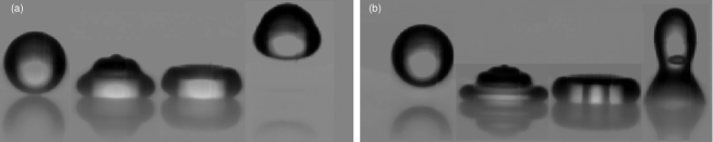
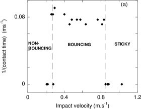
The impinging drops first expand rapidly. Subsequently, due to the hydrophobicity of the surface, the drops retract and sometimes bounce off the surface as illustrated in Fig. 1. In Fig. 2.a., the inverse of the contact time is plotted versus the impact speed. We observe that bouncing occurs only in a range of impact velocities (). As previously discussed by Richard et al. in [16], the contact time does not depend on . Looking more carefully at the retraction dynamics, three distinct regime can be identified.

– : sticky droplets. In this regime, the contact line hardly retracts and the intantaneous contact angle reaches values as small as , see Fig 1.b. This strong pinning is a clear evidence that the microstructure has impaled the liquid surface. Observations with a microscope have systematically confirmed that the pillars are impregnated.
– : bouncing droplets. At intermediate velocities, the drop bounces on the surface (this behavior is never observed on flat PDMS), several bouncing events can be observed. Finally, the drop remains on the surface adopting a large contact angle consistent with the Cassie-Baxter prediction. The initial kinetic energy of the drop is not sufficient to overcome the energy barrier hindering the impalement transition.
– : non-bouncing droplets. As previously reported in [17], we obseve a low speed threshold below which droplets do not bounce anymore. In this regime, the drop weakly expand after impact. Then, the drop undergoes damped oscillations to reach its a quasi-spherical shape, corresponding again to a fakir non-wetting state. Though bouncing is not observed, water does not fill the microstructure.
Varying the height of the pillars we construct the phase diagram plotted in Fig. 2.b. The kinetic energy thresholds delimiting the three regimes are plotted versus .
The non-bouncing to bouncing transition can be easily understood. During the drop retraction stage, we assume that the pinning of the contact line is the main source of kinetic energy dissipation. Denoting the liquid-air surface tension and the contact angle hysteresis of the fakir drop (independent of ), we can assess the pinning force per unit length: . The minimal kinetic energy needed to observe bouncing thus scales . The order of magnitude of this energy threshold is , in good agreement with what is experimentally observed.
The critical impalement threshold delimiting the bouncing and the sticky regimes exhibits nontrivial variations with , see Fig. 2.b. For short pillars, the critical kinetic energy increases linearly with . Above , it becomes independent of the texture roughness. We insist on the irreversible nature of the impalement transition whatever the equilibrium wetting states. This result is one of our most important finding.
We now have to identify the physical mechanism hindering the liquid impalement upon impact of a droplet. A priori, both capillary and hydrodynamic forces, act on the liquid surface to impede the impalement process. We disentangle the two effects by performing two sets of systematic quasistatic experiments. This allows to asses to role of the sole capillary forces.
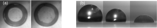
– Squeezing [18]: A droplet is squeezed between, a microstructured substrate and a fluorinated glass slide (advancing contact angle with water ). The drop is observed through the glass plate (see Fig. 3.a). The gap between the substrate and the glass plate is slowly decreased until we observe a rapid jump forward of the contact line on the PDMS substrate. This jump is the signature of the liquid impalement. The increase of the drop Laplace pressure is the motor behind the liquid impalement. Fitting the droplet shape just before the transition by a surface with a constant mean curvature (), we infer a critical impalement Laplace pressure . Fig. 4. For the microstructures made of long pillars, our experimental setup did not allow to reduce the gap between the two solid surfaces sufficiently to observe the impalement transition. To circumvent this technical obstacle, we used an alternative method to increase the Laplace pressure in the drop.
– Evaporation: A millimetric water droplet is gently deposited on the microstructured substrates. Since the drop evaporates, its radius slowly decreases with time, hence its curvature and the Laplace pressure pushing the liquid surface on the micropillars rise continuously. After few minutes, the drops adopts its receding contact angle () and the contact line retracts. Again, above a critical pressure , one can observe a sudden variation of the contact angle and a strong pinning of the contact line that stops its retraction until complete evaporation, see Fig. 3.b. These two observations witness the drop impalement transition. Once a drop has reached a Wenzel state, it never relaxes toward a fakir conformation. We emphasize that arbitrarily small drops cannot be maintained in a fakir state. This results seems to be at odd with the the criterion: which is independent of the drop size. We point out that this criterion has been established ignoring any pressure difference across the liquid interface, i.e. for infinitely large drops.
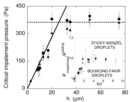
To quantitatively compare the outcome of our quasistatic and impact experiments, we assess the pressure pushing the liquid interface when a water drop hits the micropillars. Neglecting any viscous effect, the dynamic pressure acting on the liquid interface scales as , with the liquid density. Fig. 4 gathers static and impact experimental data. The collapse of our data on a single master curve is a strong evidence that, hydrodynamic forces do not play any significant role in the impalement transition on our surfaces rough at the 10 microns scale. The wetting of the microstructure is mainly hindered by capillary forces. This constitutes our second main results.
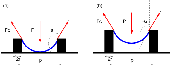
We have unambiguously identified the forces impeding the fakir to Wenzel transition, we can now propose a simple semi-quantitative model to account for the relation between the pattern geometry and the critical impalement pressure. Whatever its precise origin (curvature, liquid flow,…), the internal drop pressure pushes the liquid interface downward. A force is experienced by the liquid free surface enclosed by an elementary cell of the lattice, where we have denoted the projected area of one cell. At mechanical equilibrium, this force is balanced by the capillary force, applied at the top of pillars, see Fig. 5. Here is the ”average” contact angle defined on the pillars sides. Writing explicitly the equilibrium condition , we obtain:
| (1) |
Note that in the above equation the precise shape adopted by the liquid interface is encoded solely in the prefactor.
We now propose two impalement scenarios characterized by two critical values of the contact angle on the pillars.
– ”Touch down” scenario: increasing the drop pressure, the curvature of the interface increases. This implies that the minimal height separating the liquid interface and the basal surface of the substrate diminishes. Fakir states cannot be stabilized if this minimal height goes to zero, see Fig. 5.a. This contact condition can be expressed in term of a critical angle value . An exact computation of this critical angle would require the full determination of the drop shape. To bypass this difficulty, we can estimate this critical angle in a much simpler manner. Using a the small deformation approximation it is straightforward to compute profile of a fluid interface lying on top of two concentric cylinders (radius and ). For this simplified geometry, one can easily show that, , for and omitting logarithmic corrections. It then follows that the critical ”touch down” impalement pressure scales at first order with respect to the solid fraction [19]:
| (2) |
where we have used for a triangular lattice. Note that for denser patterns, i.e. for , woulf scale as . The above equation would then be modified and . For weakly rough substrates, Eq. 2 correctly predicts the linear scaling of the impalement pressure with respect to the pillars height reported in Fig. 2 and Fig. 4. Though several simplifications were made one can compare the estimate of the numerical prefactor to its experimental value. For the surface, Eq. 2 predicts a slope , the slope extracted from Fig. 4 is times smaller. We do not think that this slight difference arises solely from the approximations needed to estimate , a precise numerical description of the free surface actually increases this discrepancy. We will show elsewhere that localized heterogeneities are good candidates to account for the overestimate of the value [20]. Indeed, the effect of chemical or geometrical heterogeneities cannot be captured by our simple ”mean field” model.
– ”sliding” scenario: For higher pillars a transition to a critical impalement pressure independent of the aspect ratio can understood as follow. The contact angle has another upper limit, namely the local advancing contact angle value . If exceeds , the contact line will spontaneously slide downward along the pillars to reach the floor of the microstructure. Therefore, this critical ”sliding” impalement pressure is obtained taking in Eq. 1:
| (3) |
Beyond the correct scaling prediction equation Eq. 3 provides a rather good estimate of the experimental prefactor value for the two tested patterns, see inset in Fig. 4. A factor of is as good as we could have expected given the simplicity of our model and the precision of the microfabrication process.
This simplified model conveys a clear picture to account for the relation between the micropattern geometry and the robustness against liquid impalement. The drop will undergo an impalement transition if the pressure in the drop exceeds , the crossover between the two impalement scenarios corresponds to an aspect ratio for low patterns.
We eventually emphasize that the above description may be a useful guide for the design of superhydrophobic surfaces. Efficient water repellent surfaces must obviously exhibit a high Young contact angle, a small contact angle hysteresis and a strong resistance against irreversible impalement. The two first requirements can be achieved reducing the solid fraction . The sole comparison of the surface energies associated with Fakir and Wenzel states would lead to the fabrication of substrates as rough as possible. We have shown that, for a given solid fraction and above a roughness threshold the value of the energy barrier stabilizing the fakir states remains constant. Thus, putting efforts to design ultra rough surface seems ineffective. Conversely, reducing the size of the elementary pattern of the surface would arbitrarily increases the resistance against impalement [21]. We precise that this conclusion relies on the quantitative agreement between our impact and quasistatic experiments. However, for impacts on substrates patterned at ultra-small scales, the confinement of the fluid flows would enhance the magnitude of the hydrodynamic forces hindering impalement.The identification of this characteristic scale at which they would overcome capillary effects remains an open question.
Acknowledgments: M. Callies and D. Quéré are gratefully acknowledged for insightful discussions and stimulating interactions. We thank A. Ajdari, D. Bonn and J. Meunier for useful comments and suggestions.
References
- [1] \NameNeinhuis C. Barthlott W \REVIEWAnn. Botany791997668.
- [2] \NameShibuichi S., et al \REVIEWJ. Phys. Chem.100199619512.
- [3] \NameLau K. K.S, et al. \REVIEWNano Letters320031701.
- [4] \NameKrupenkin T., et al. \REVIEWLangmuir2020043824.
- [5] \NameBlossey R. \REVIEWNature Mat.22003301.
- [6] \NameQuéré D. \REVIEWPhysica. A313200232.
- [7] \NameWenzel R. N. \REVIEWInd. Eng. Chem.281936988.
- [8] \NameCassie A. B. D. Baxter S. \REVIEWTrans. Faraqy Soc.401944546.
- [9] \NameLafuma A. Quéré D. \REVIEWNature Mat.22003457.
- [10] \NameHe B., Patankar N. A. Lee J. \REVIEWLangmuir1920034999.
- [11] \NameXia Y.Whitesides G. \REVIEWAngew. Chem. Int. Ed.371998550.
- [12] \NamePatankar \REVIEWLangmuir2020047097.
- [13] \NameCarbone G. Mangialardi L. \REVIEWEur. Phys. J. E16200567.
- [14] \NameIshino C., Okumura K. Quéré D. \REVIEWEurophys. Lett.682004419.
- [15] \NameCottin-Bizonne C., Barentin C., Charlaix E., Bocquet L., Barrat J.-L. \REVIEWEur. Phys. J. E152004438.
- [16] \NameRichard D., Clanet C. Quéré D. \REVIEWNature502000769.
- [17] \NameRichard D. Quéré D. \REVIEWEurophys. Lett.4172002811. .
- [18] \NameJournet C. et al. \REVIEWEurophys. Lett.712005104.
- [19] A similar criterion obtained using a different approach has been proposed in: \NameBico J. \BookPhd thesis.
- [20] \NameMoulinet S. Bartolo D. \Bookin preparation.
- [21] \NameCallies M. Quéré D. \Booksubmitted