Local field of magnetic islands: role of their shape
Abstract
I analyze in details distribution of local magnetic field induced by micro- and nano-magnets. I consider three kinds of elongated magnetic islands: ellipse-, diamond- and rectangular shaped islands which were magnetized uniformly along long axis. This report concentrates on the role of their shape upon distribution of the field. Calculations show that unlike rectangular-shaped magnet, ellipse-shaped and diamond-shaped ones produce much more localized field in proximity of its magnetic poles. Additionally in the case of ellipse-shaped islands the magnitude of induced field is large. This two facts favor arrays of ellipse-shaped magnetic islands to build zero-dimensional spin traps in a hybrid based on Ferromagnet/Semiconductor structure.
I Introduction
Basic research in the physical sciences, especially in condensed matter physics, can result in important developments in applied physics and engineering. Recently scientists draw theirs attention to the physics of hybrid structures. Both (Ferromagnet)/(Magnetic Semiconductor)Crowell et al. (1997); Tanaka (2002) and (Superconductor)/(Magnetic Semiconductor),Berciu et al. (2005); Castellana et al. (2005) are promising hybrids that join magnetic and electronic properties in one unit. Using Magnetic Semiconductor or more precisely Diluted Magnetic Semiconductor (DMS), e.g., CdMnTe, GaMnAs instead of a Conventional alloy (CdTe, GaAs) amplifies some physical properties which are extremely small in a (Ferromagnet or Superconductor)/(Conventional Semiconductor) hybridMichel et al. (2005). The effect that lies the foundation of such amplification is called Giant Zeeman EffectFurdyna and Kossut (1988) and is due to the sp-d exchange interaction between delocalized (s, p) and localized (d) carries. Let us concentrate on the (Ferromagnet)/(DMS) hybrid. When DMS is buried below array of magnetic islands, local field produced by each island is penetrating DMS structure. DMS acts itself as an amplifier and multiplies this field by huge factor (typically by hundred times but in sub-Kelvin temperatures even by thousand times). In this way quasi-particles fill large, effective ”potential” proportional to this local field and which acts as a trap for them. Depending on the local distribution of the magnetic field the effective potential can reveal one-dimensionalRedliński et al. (2005a) or zero-dimensionalRedliński et al. (2005b) character. In this report I analyze the role of shape of the islandsLebecki (2004) on the distribution of induced field so on possibility of localization of quasi-particles.
Micro- and nano-magnets of different kind of shapes have already been investigated experimentally: diamond-like magnetsRahm et al. (2001), cylinder-like magnetsRoss et al. (2002) as well as rectangle-like magnetsKossut et al. (2001); Crowell et al. (1997); Van Bael et al. (1999) are examples of them. Typically, the structures of arrays of magnets is characterized by Atomic-Force Microscopy (AFM), the magnetic properties are studied by Superconducting QUantum Interference Device (SQUID) magnetization measurements and in order to obtain local microscopic information on the domain structure of the individual islands, Magnetic-Force Microscopy (MFM) measurements is performed. Recently we have presentedRedliński et al. (2005a, b) theoretical analysis of the absorption spectrum as well as distribution of the local magnetic field induced in (Ferromagnet)/(DMS) hybrid composed of rectangular and/or cylindrical island and DMS quantum well structure. We have shown that depending on the distribution of the magnetic field it is possible to localize quasi-particle in this type of system.
In the next section I present theoretical assumptions concerning the system as well as describe procedure of calculation of magnetic field induced by a magnets. Then I analyze results in more details and draw conclusions.
II Theory and Numerical Procedure
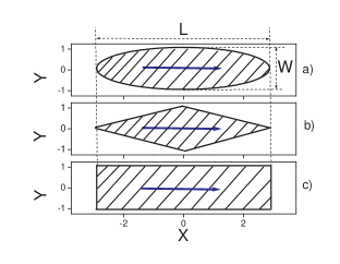
I considered three types of flat islands which volumes . Shape is one of ellipse-, diamond- or rectangle shapes as shown on Fig. 1 and is height of the magnet. In my coordinate system, magnet is lying on the XY plane and I assumed that the aspect ratio between its length and its width equals to three, , and the aspect ratio between its width and its height is assumed to be 10, . For example, the following numbers fulfil the assumptions: length =6 m, width =2 m and height =0.2 m - so magnet is called a micro-magnet. Islands are magnetized uniformly in the x-direction as indicated on Fig. 1. Z-component of induced magnetic field was calculated at points on the XY plane at the distance below islands.
Magnetic field is a function of all four lengths: , , , and is proportional to the saturation magnetization : . As can be checked by solving magneto-static Maxwell’s equationsJackson (1999) the following scaling is fulfilled: which allows us to work with dimensionless lengths indicated on Fig. 1 and in the following presentation.
Magnetic field coming from uniformly magnetized cuboid can be calculated analytically as shown for example in Ref. Engel-Herbert and Hesjedal, 2005. I use this fact and approximate volume of the whole magnet by a sum of volumes of small cuboids , , which are totally included in the volume of island, . Then, using the fact that Maxwell equations are linear, I can approximate total magnetic field at point by a sum of partial fields produced by each cuboid :
| (1) |
that approximate real field (for the rectangular shaped magnet ) depends on the division of the volume . I used small volumes to represent each cuboid and assured that . Typically which have given us smooth magnetic field after performing summation as required in Eq. (1). In the further discussion symbol will be used instead of to simplify notation.
III Results and Discussion
In order to compare results obtained for all three shapes I set =6 m, =2 m and =0.2 m in the case of all types of islands. Magnetic field was calculated at the same distance =10 nm=0.01 below each micro-magnet. Each micro-magnet was magnetized uniformly to the value of the saturation magnetization of iron =1740 . In Tab. 1 I collected saturation magnetization of few other substances.
| Substance | [emu/cm3] | [T] | [1] |
|---|---|---|---|
| Fe | 1740 (1707) | 2.19 (2.15) | 1.00 |
| Co | 1446 (1400) | 1.82 (1.76) | 0.83 |
| Ni | 510 (485) | 0.64 (0.61) | 0.29 |
| Dy | 2920 (-) | 3.67 (-) | 1.68 |
| MnAs | 870 (670) | 1.1 (0.84) | 0.50 |
| MnSb | - (710) | - (0.89) | 0.41 |
Results scales simply with and it is straightforward to obtain distribution of the magnetic field of other substances by multiplying results by the factor (Substance)/(Fe) which I show in the last column of Tab. 1. For example, when considering MnAs island instead of Fe island, the results have to be multiplied by a factor of .
Fig. 2 shows contour plot of the z-component of the magnetic field, , of ellipse shape micro-magnet (panel a), of diamond shape micro-magnet (panel b) and of rectangle shape magnet (panel c). White (black) color indicates region with positive (negative) value of and gray color indicates .
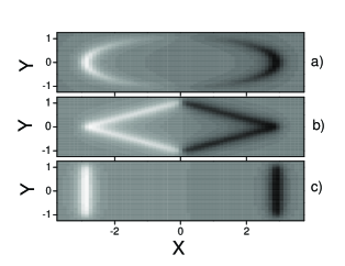
As seen on Fig. 2 distribution of magnetic field on the XY plane is highly position-dependant and shape-dependant. Large fields are induced in proximity of magnetic poles below and above them. In the further discussion I will use magneto-static language and use notion of the density of magnetic charge . Total magnetic charge is the same for all shapes of islands because I have chosen identical for all types micro-magnets. Magnetization , and density of magnetic charge where is a unit vector normal to the surface at point . It means that in the case of diamond and rectangle shapes is a constant on the surface of micro-magnets because normal to its surface does not depend on the position. In the case of diamond-shape magnet is times smaller than of rectangle-shape magnet because surface area is time larger in the case of diamond-shape magnet. From this fact we expect that magnitude of is about smaller in the case of diamond shape then of rectangle shape. As we shall see later three dimensional plots confirm this fact. In the case of ellipse-shape magnet normal to the surface changes with position on the surface so does . Fig. 2 reflects the distribution of magnetic charge.
To gain more knowladge about distribution of the field now I present three dimensional plots of in the region of its large value.
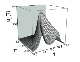
Figures 3, 4 and 5 show z-component of the magnetic field, , that is produced by the micro-magnets of ellipse, diamond and rectangle shape, respectively. Induced fields can be directly compared because all three scales are the same on the figures. In all three cases, as before, magnetic field is calculated at the distance =10 nm below micro-magnets and, as before, =6 m, =2 m, =0.2 m. I plotted only region below left pole in its close proximity. On the right pole has opposite sign. We see again that in the case of ellipse magnet, Fig. 3, induced field is highly localized around point (0, -3). Magnitude of is almost 0.4 T and is almost the same as in the case of rectangular island, Fig. 5.
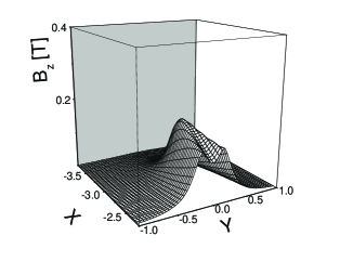
In the case of diamond-like magnet, Fig. 4, magnetic field is localized around point (0, -3), too, but the amplitude is much lower then in the case of ellipse magnet. There exist large component of the magnetic field below edges of the whole magnet.
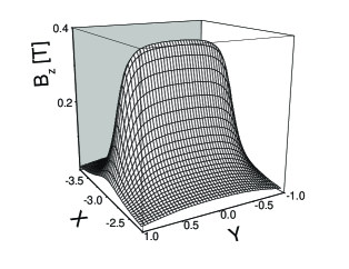
In the case of rectangular magnet large component exists below whole left and right edge of the island. As was shown in Ref. Redliński et al., 2005b such elongation of the local field can produce one-dimensional traps for quasi-particles. Presented analysis and figures allow us to conclude that in the case of ellipse sample zero-dimensional spin-traps can be realized in the (Ferromagnet)/(DMS) hybrid.
IV Conclusions
I analyzed distribution of the magnetic field induced by micro- and nano-magnets of three different shapes: ellipse, diamond and rectangle. As a main results I have found that the shape of islands has large impact on the distribution of induced field. My calculations show that ellipse-shaped island produces much more localized fields in proximity of its magnetic poles in contrast to rectangular-shaped island. Additionally, magnitude of this field is large and almost the same as a magnitude of the field induced by rectangular shape. I expect that (Ferromagnet)/(DMS) hybrid composed of ellipse micro-magnet and DMS quantum well structure will produce zero-dimensional traps for quasi-particle.
V Acknowledgement
I would like to thank Dr K. Lebecki for useful discussions concerning this topic as well closely related problems.
This material is based in part upon work supported by the NSF DMR02-10519. Any opinions, findings, and conclusions or recommendations expressed in this material do not necessarily reflect the views of the NSF.
References
- Crowell et al. (1997) P. A. Crowell, V. Nikitin, D. D. Awschalom, F. Flack, N. Samarth, and G. A. Prinz, Journal of Applied Physics 81, 5441 (1997).
- Tanaka (2002) M. Tanaka, Semicond. Sci. Technol. 17, 327 (2002).
- Berciu et al. (2005) M. Berciu, T. G. Rappoport, and B. Jankó, Nature 435, 71 (2005).
- Castellana et al. (2005) C. Castellana, F. Giazotto, M. Governale, F. Taddei, and F. Beltram, cond-mat/0508058 (2005).
- Michel et al. (2005) C. Michel, C. H. Thien, S. Ye, P. J. Klar, W. Heimbrodt, S. D. Baranovskii, P. Thomas, M. Lampalzer, K. Volz, W. Stolz, et al., Superlattices and Microstructures 37, 321 (2005).
- Furdyna and Kossut (1988) J. K. Furdyna and J. Kossut, Diluted Magnetic Semiconductors (Academic, Boston, 1988).
- Redliński et al. (2005a) P. Redliński, T. Wojtowicz, T. G. Rappoport, A. Libál, J. K. Furdyna, and B. Jankó, Appl. Phys. Lett. 86, 113103 (2005a).
- Redliński et al. (2005b) P. Redliński, T. Wojtowicz, T. G. Rappoport, A. Libál, J. K. Furdyna, and B. Jankó, Phys. Rev. B 72, 085209 (2005b).
- Lebecki (2004) K. Lebecki, private communications (2004).
- Rahm et al. (2001) M. Rahm, J. Bentner, J. Biberger, M. Schneider, J. Zweck, D. Schuh, and D. Weiss, IEEE Trans. Mag. 37, 2085 (2001).
- Ross et al. (2002) C. A. Ross, M. Hwang, M. Shima, J. Y. Cheng, M. Farhoud, T. A. Savas, H. I. Smith, W. Schwarzacher, F. M. Ross, M. Redjdal, et al., Phys. Rev. B 65, 144417 (2002).
- Kossut et al. (2001) J. Kossut, I. Yamakawa, A. Nakamura, G. Cywiński, K. Fronc, M. Czeczott, J. Wróbel, F. Kyrychenko, T. Wojtowicz, and S. Takeyama, App. Phys. Lett. 79, 1789 (2001).
- Van Bael et al. (1999) M. J. Van Bael, K. Temst, V. V. Moshchalkov, and Y. Bruynseraede, Phys. Rev. B 59, 14674 (1999).
- Jackson (1999) J. D. Jackson, Classical electrodynamics (Wiley, New York, 1999), xxi ed.
- Engel-Herbert and Hesjedal (2005) R. Engel-Herbert and T. Hesjedal, Jour. Appl. Phys. 97, 2074504 (2005).
- Kittel (1996) C. Kittel, Introduction to Solid State Physics (John Wiley and Sons, New York, Chichester, 1996), vii ed.