Domain imaging, MOKE and magnetoresistance studies of CoFeB films for MRAM applications
Abstract
We present a detailed study on domain imaging, Kerr effect magnetometry (MOKE) and magnetoresistance (MR), for a series of 20 nm Co73.8Fe16.2B10 thin films, both as-deposited (amorphous) and annealed (crystalline). By considering the two different (orthogonal) in-plane magnetization components, obtained by MOKE measurements, we were able to study the uniaxial anisotropy induced during CoFeB-deposition and to discriminate the magnetization processes under a magnetic field parallel and perpendicular to such axis. MOKE magnetic imaging enabled us to observe the dominant magnetization processes, namely domain wall motion and moment rotation. These processes were correlated with the behavior of the magnetoresistance, which depends both on short-range spin disorder electron scattering and on the angle between the electrical current and the spontaneous magnetization (). A simple numerical treatment based on Stoner-Wolfarth model enables us to satisfactorily predict the magnetization behaviour observed in these films. A comparison between the results in Co73.8Fe16.2B10 films and the previous ones obtained in annealed Co80Fe20 films, show that the introduction of boron in CoFe reduces significatively the coercive and saturation fields along the easy axis (e.g. from 2 down to 0.5 kAm-1). Also, the magnetization along the hard axis saturates at lower fields. We conclude that amorphous and nanocrystalline CoFeB films show low coercive fields and abrupt switching, as well as absence of short range spin disorder effects after switching when compared with Co80Fe20.
keywords:
Tunnel Junction, magnetic coupling, Domain Imaging, Magneto-Optical Kerr effect, Anisotropic Magnetoresistance, magnetic reversal processesPACS:
73.40.Gk, 73.40.Rw, 85.35.-p, 85.75.-d, 85.75.Dd1 Introduction
Tunnel junctions (TJ) consisting of two ferromagnetic (FM) layers separated by an insulator [1] are strong candidates for leading technological applications such as sensor elements in read heads [2] and non-volatile magnetic random-access memories (MRAMs) [3]. The magnetization of one of the FM layers (pinned layer) is fixed by an underlying antiferromagnetic (AFM) layer, whereas the magnetization of the other FM layer (free layer) reverses almost freely when a small magnetic field is applied. Due to spin dependent electron tunneling one can thus have two distinct resistance (R) states, associated with the magnetizations of the pinned and free layers parallel (low R) or antiparallel (high R). To improve device performance, one continuously aims to achieve higher tunnel magnetoresistance (TMR), better thermal stability and low ferromagnetic coupling () between pinned and free layers. The use of amorphous CoFeB films in the free and pinned layers of optimized tunnel junctions enabled us to obtain a TMR coefficient as high as 70% [4], good transport properties upon annealing up to 673 K [5] and coercive and coupling fields as low as 160 Am-1 [6].
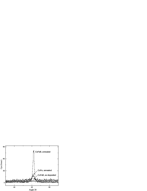
Here we present a study on the magnetoresistance (MR), Kerr Effect vectorial magnetometry and domain imaging of a series of 20 nm (Co73.8Fe16.2)B10 films, both as-deposited and annealed. A CCD camera with 10 m resolution enabled direct domain visualization. X-ray diffraction showed that the annealed films were crystalline, with a strong (110) texture, while the as-deposited CoFeB films were amorphous [6].
By considering the two different in-plane magnetization (M) components (given by vectorial MOKE magnetometry), we study the M-processes under longitudinal (easy axis) and transverse (hard axis) fields (H). The results are compared with simultaneous MR measurements and magnetic domain visualization. Under transverse fields magnetic rotation processes dominate and lead to good correlation between the behavior of M, MR and domain changes under H. For longitudinal fields the M-processes are mainly due to domain wall displacements ( magnetization reversals) and no MR dependence is observed in this case, both for the annealed and amorphous CoFeB films. Thus, the uniaxial anisotropy is responsible for the different magnetization reversal processes observed when the H is applied along the easy or hard axes.
2 Experimental Details
We studied a series of as-deposited and annealed (10 min. at 553 K) (Co73.8Fe16.2)B10 thin rectangular films (4 mm 4 mm 20 nm for the as-deposited sample and 3 mm 14 mm 20 nm for the annealed sample) grown on glass substrates by ion-beam deposition [6]. A magnetic field of Am-1 was applied along the longitudinal direction during deposition, inducing an easy axis direction in all the studied films. The magnetic properties were investigated at room temperature by Magneto-Optical Kerr effect (MOKE), domain imaging and MR measurements [7]. MOKE hysteretic cycles were obtained using a vectorial MOKE magnetometry unit simultaneously measuring both in-plane magnetization components, allowing us to obtain the technical magnetization vector M(H) in the two common in-plane geometries: the transverse geometry, with H in the film plane and perpendicular to the laser-beam incident plane; and the longitudinal geometry, in which the in-plane field is parallel to the incident plane. A greyscale CCD camera with m of resolution is used to acquire the magnetic domain images. Each image is saved in a bitmap format with 8 bit of information and is then differentiated with respect to the magnetically saturated image to enhance image contrast. In both systems the sample is located in the center of a pair of Helmholtz coils.
The four probe technique was used for the MR measurements, with the electric current along the long axis of our rectangular films and the in-plane applied magnetic field parallel or at right angles to the electrical current. In ferromagnetic 3d-transition metals the electric resistivity depends on the angle between the electrical current and the spontaneous magnetization , through the so called anisotropic magnetoresistive effect (Smit mechanism; see [8]):
| (1) |
where is the resistivity when M is saturated perpendicular (parallel) to the electrical current. A magnetoresistive coefficient (at field H) is defined as:
| (2) |
For a film with always in plane and starting with a random demagnetized state one has . If the film has uniaxial anisotropy ( domains) one then simply has . The so called anisotropic magnetoresistance ratio (AMR) is given by [8]:
| (3) |
3 Experimental Results
3.1 MOKE magnetometry and imaging
The magnetic loops obtained for the Co73.8Fe16.2B10 thin films (as-deposited and annealed) are presented in Fig. 1. The uniaxial anisotropy impressed during film growth is readily apparent, having the easy (hard) axis oriented parallel (perpendicular) to the light scattering plane defined by the incident laser beam and the film normal. The easy direction coincides with the long axis of the rectangular films.
For H parallel to the easy axis we observe, in the as-deposited CoFeB film (Fig. 1a), a rectangular hysteretic cycle with a coercive field 477 Am-1, whereas 955 Am-1 for the annealed film (Fig. 1e) i.e. the amorphous state reduces the coercive field by a factor of 2. The saturation magnetic field (; taken where irreversibility vanishes and a constant magnetization plateau sets in) is also greatly reduced, from 1990 Am-1 for the annealed film to 1273 Am-1 in the amorphous CoFeB film. As expected, a zero transverse magnetization component is measured in both films under a longitudinal magnetic field (Figs. 1b and 1f).
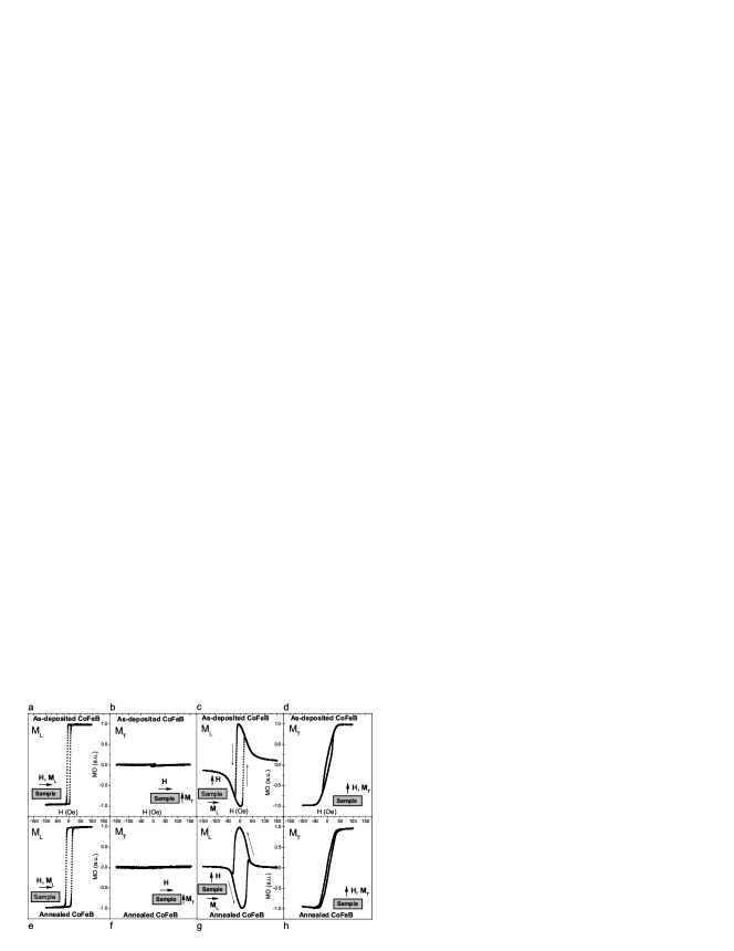
For H perpendicular to the easy axis, typical quasi-linear transverse-component cycles are observed as displayed in Figs. 1d and 1h. However, small coercive fields are still observed, of 557 Am-1 and 318 Am-1 for the as-deposited and annealed films respectively, leading to very narrow hysteretic cycles; the saturation field is virtually the same in both cases, Am-1 (here is taken where the magnetization plateau sets in; for H along the hard direction, this occurs above the irreversibility point). On the other hand, the longitudinal magnetization component in both films (, Figs. 1c and 1g) exhibits a small field dependence on the approach to saturation, except for the sudden magnetization reversal at 1194 Am-1 and 2228 Am-1, for the as-deposited and annealed CoFeB films respectively. On the other hand, 7960 Am-1 in both cases.
Comparing these results with those previously obtained in annealed Co80Fe20 films [7], we notice that the introduction of boron in CoFe (favouring amorphous/nanocrystalline structures; Fig. 2) reduces significatively the coercive and saturation fields along the easy axis ( Am-1 and Am-1 in Co80Fe20). Also, the magnetization along the hard axis saturates at lower fields in the CoFeB films (both as-deposited and annealed) than in the annealed CoFe film ( 5970 Am-1).
The differences observed in the curves for the two in-plane MOKE geometries (longitudinal and transverse) are a consequence of the two main reversal processes, rotation and domain wall propagation [9]. This was confirmed by visualization of the magnetic domains, as summarized in Figs. 3 and 4 for the as-deposited and annealed CoFeB films respectively (see also sections 5.1 and 5.2).
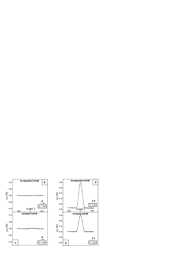
3.2 AMR measurements
The magnetoresistance vs curves with H parallel and perpendicular to the electrical current [8] are shown in Fig. 5. The magnetoresistance is zero when the current and magnetic field are parallel (Figs. 5a, 5c), and negative for the as-deposited and annealed films when they are perpendicular ( and ; Figs. 5b, 5d). An AMR ratio of 0.24% and 0.15% results from these later data, for the as-deposited and annealed films respectively.
For the transverse configuration one can correlate the behaviour with that observed in M(H), while under parallel magnetic fields no correlation is possible since MR = 0 (see section 6).
4 Numerical analysis of behaviour
A simple treatment based on the Stoner-Wolfarth model satisfactorily describes the qualitative behaviour of the magnetization when the orientation of the magnetic field is changed. According to this model, coherent magnetization rotation is assumed. The relevant magnetic energy per unit volume () is written as the sum of Zeeman () and anisotropy (; anisotropy constant ) energies:
| (4) |
For an applied (in-plane) magnetic field making an angle with the easy axis, and a magnetization making an angle with the same axis, one can write:
| (5) |
We numerically obtain the angle which minimizes E (for each value of H with a fixed orientation) and then calculate the magnetization components and . The results are illustrated in Fig.6, for , , and . The magnetic field is normalized by the anisotropy field /, where is the spontaneous magnetization.
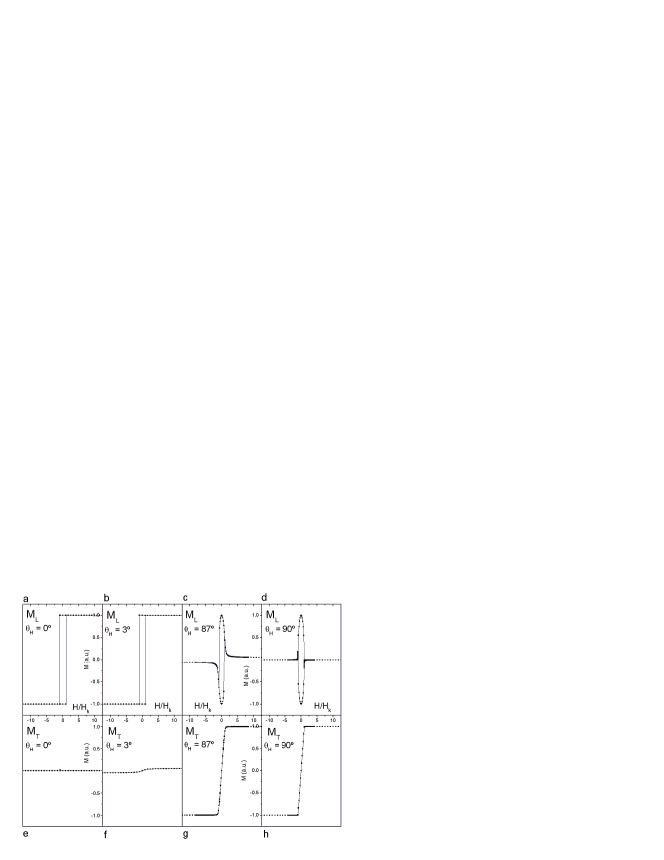
One sees that when H is not exactly parallel or perpendicular to the easy axis (), the magnetization processes become more complex. For small values, i.e. small H deviations from the easy axis, the and hysteretic cycles are hardly affected, because the small transverse magnetic field component occurs along the hard direction for which the magnetic susceptibility is rather low.
In contrast with this situation, for a small field misalignment produces a field component along the easy axis, which induces a significant component due to the high magnetic susceptibility along such direction. A more detailed analysis is given in next section.
5 Analysis of and behaviour
5.1 As-deposited CoFeB film
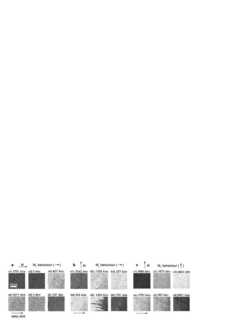
The rectangular easy-axis magnetization curve in Fig. 1a, for the as-deposited CoFeB film, clearly indicates an abrupt magnetization switching, which is directly confirmed by the corresponding domain images in the backward (Fig. 3a13a3) and forward branches (Figs. 3a43a6) of the loop. These sequences demonstrate a sudden transition from one saturated magnetic state (single domain; dark image) to the opposite state (single domain; bright image), corresponding to a reversal of the magnetic domains through domain wall motion.
When the magnetic field is applied along the hard axis (Fig. 1d) the growth of the transverse magnetization is quite gradual (almost linear-like), as also revealed by the intensity of the MOKE images (Figs. 3c13c6), indicating the progressive rotation of the magnetization. On the other hand, the component (Fig. 1c) indicates that the magnetization undergoes a rotation in the plane of the film, always in the same sense. This process has two distinct regimes: one leading to a gradual dependence associated with domain rotations (), and the other producing abrupt steps in the magnetization, attributed to domain-wall displacements (switching). As shown in the images in Figs. 3b13b3 for the backward branch, initially (high fields) one observes a progressive increase in the image brightness (proportional to ), associated with rotation processes, while Figs. 3b43b6 evidence abrupt changes in the image intensity (from bright to dark) under small fields, due to the sudden magnetization switching (180∘). Thus, with H along the hard axis we detect both magnetization reversal processes, with dominance of magnetic domain rotations under high fields, and sudden M-switching at low fields (domain wall motions).
We show numerically that when the magnetic field is perfectly aligned with the hard axis (Figs. 6d and 6h), the expected (Stoner-Wolfarth model) magnetization process from one saturated state to another occurs only by coherent moment rotations, with no sudden M-switching. However, due to an experimentally unavoidable small H-misalignments with the hard axis, and incoherent magnetization processes in real films, the two magnetization processes (domain wall displacements and rotations) are experimentally observed. The discontinuities (”jumps”) given by the Stoner-Wolfarth model, when there is a misalignment or when the magnetic field is parallel to the easy-axis (Figs.6a, 6c, 6e and 6g), are physically due to domain wall motions.
5.2 Annealed CoFeB film
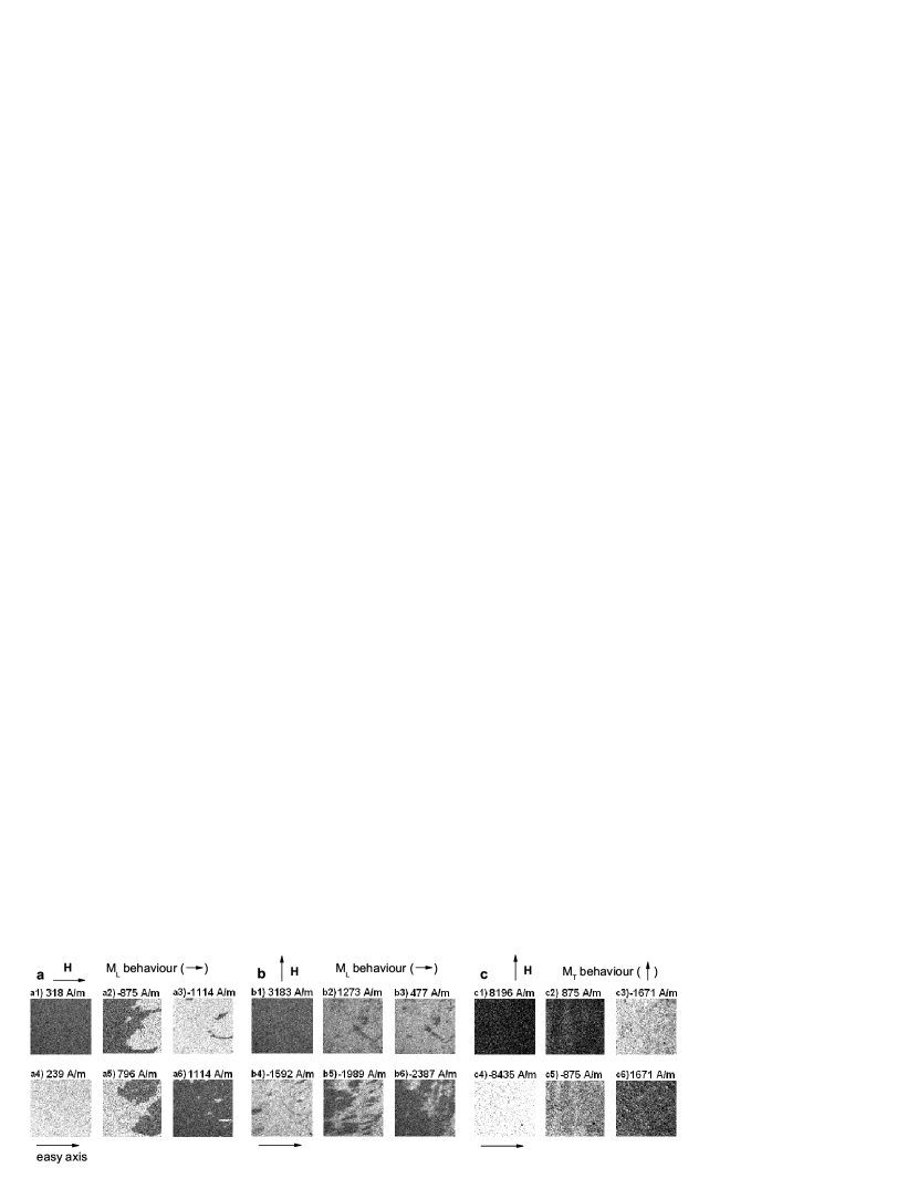
For the applied field along the easy axis, the MOKE results for the annealed CoFeB film reveal again a rectangular magnetization loop (Fig. 1e). Thus, the single domain magnetization is switched from one direction to the opposite in an extremely small field range, due to 180∘ domain-wall formation and fast wall propagation, with no transverse magnetization component (; Fig. 1f).
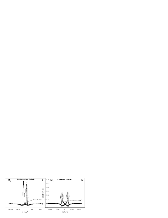
With the magnetic field along the hard axis (Figs. 1g and 1h), we find again that the magnetization process occurs through domain wall motion (switching at low fields) and magnetic moment rotations. The domain wall displacements are detected by the component (Fig. 1g), through the rapid change in within a small field range. The much more gradual dependence (Fig. 1h), and also in some parts of (Fig. 1g), is attributed to domain rotations. Magnetic domain visualization shows a complex pattern (Fig. 4b5), with nucleation and propagation of magnetic domains through domain walls of reduced wall angle (less than 180∘), since the variation of intensity between the bright and dark regions is not so strong as previously observed for the as-deposited CoFeB film with H along the hard axis (Fig. 3b5). A careful analysis of the curve, using the highly sensitive and numerically obtained derivatives, shows that such domain wall propagation begins well after the maximum (Fig.7b; sharp peak in at Am-1 for the backward branch), contrarily to the situation observed in the as-deposited CoFeB sample (Fig.7a; peak at Am-1 for the backward branch), indicating that some of the magnetic moments leave the easy axis.
Again, a qualitatively good correlation between the numerical results and the experimental ones is observed. As above, due to an small H-misalignments with the hard axis, both reversal processes are present. The discontinuities given by the Stoner-Wolfarth model (Figs.6a, 6c, 6e and 6g) are real and physically related to domain wall displacements.
6 AMR versus M(H) behaviour
The magnetoresistance measurements show that is very sensitive to the type of processes underlying the magnetization reversal.
Under transverse magnetic fields, when magnetization rotation dominates, we have similar saturation magnetic fields in the and curves. In this geometry, for which domain rotations dominate, we indeed expect important variations in the resistivity with magnetic field through the Smit mechanism (Eq. (1)). At low (transverse) fields the longitudinal magnetization component displays a maximum and the magnetoresistance is very small, since the magnetic moments are essentially aligned along the easy axis ( or ; MT/ML 1) and, according to Eq. (1), which leads to .
Under longitudinal magnetic fields, the magnetization loops and magnetic domain images of Figs. 1a, 1e, 3a and 4a indicate magnetization switching at low fields, and consequently no variation in the electrical resistivity (Fig. 5; in agreement with Eq. (1), since ).
In conclusion, amorphous and nanocrystalline CoFeB films show low coercive fields and abrupt switching, as well as absence of short range spin disorder effects after switching (which were observed in crystalline CoFe thin films [7]).
Work supported in part by FEDER/POCTI/0155, IST-2001-37334 NEXT MRAM and FEDER/POCTI/CTM/59318/2004 project. J. Ventura, R. Ferreira and S. Cardoso are thankful for the FCT grants SFRH/BD/7028/2001, SFRH/BD/6501/2001 and SFRH/BPD/7177/2001 respectively.
References
- [1] J. S. Moodera, L. R. Kinder, T. M. Wong and R. Meservey, Phys. Rev. Lett. 74, 3273 (1995).
- [2] D. Song, J. Nowak, R. Larson, P. Kolbo, R. Chellew, IEEE Trans. Magn. 36 2545 (2000).
- [3] S. Tehrani, B. Engel, J. M. Slaughter, E. Chen, M. DeHerrera, M. Durlam, P. Naji, R. Whig, J. Janesky and J. Calder, IEEE Trans. Magn. 36 2752 (2000).
- [4] D. Wang, C. Nordman, J. M. Daughton, Z. Qian and J. Fink, IEEE Trans. Magn. 40 2269 (2004).
- [5] T. Dimopoulos, G. Gieres, J. Wecker, N. Wiese and M. D. Sacher, J. Appl. Phys. 96 6382 (2004).
- [6] S. Cardoso, R. Ferreira, P. P. Freitas, M. MacKenzie, J. Chapman, J. O. Ventura, J. B. Sousa and U. Kreissig, IEEE Trans. Magn. 40 2272 (2004).
- [7] J. M. Teixeira, R.F.A. Silva, J. Ventura, A. Pereira, J. P. Araújo, M. Amado, F. Carpinteiro, J. B. Sousa, S. Cardoso, R. Ferreira and P. Freitas, accepted to Materials Science Forum.
- [8] T. R. McGuire and R. I. Potter, IEEE Trans. Magn. 11, 1018 (1975).
- [9] Richard M. Bozorth, Ferromagnetism, IEEE Press (1951).
- [10] Alex Hubert and Rudolf Schäfer, Magnetic Domains; The Analysis of Magnetic Microstructures, Springer (1998).