Photon energy lifter
Abstract
We propose a time-dependent photonic structure, in which the carrier frequency of an optical pulse is shifted without changing its shape. The efficiency of the device takes advantage of slow group velocities of light attainable in periodic photonic structures. The frequency shifting effect is quantitatively studied by means of Finite Difference Time Domain simulations for realistic systems with optical parameters of conventional silicon technology.
In several applications, particularly in the field of optical signal processing, it is desirable to dispose of techniques for continuous and efficient photon energy conversion. Most of the nowadays available techniques rely on inelastic optical processes. For example, stimulated Raman scattering has been successfully employed for frequency conversion and lasingsiliconlaser . Unfortunately inelastic processes are usually not efficient, often requiring high intensities. Finding new approaches to such a task is a challenging problem. Recently Reed et al.shockwave have proposed a way to change the color of light by capturing it on a propagating shock wave front and successive reemission.
Dynamical photonic structures, in which the optical constants of the medium can be modulated while the light is propagating inside it, have been discussed very recently (see, e.g., stoppingFan and references therein). Structures of this kind, originally suggested for stopping the light, open up an intriguing research area, in particular, for storing or manipulating optical information. In this Letter we face the photon energy conversion problem exploiting the simple idea of changing the photon frequency using materials with time-dependent optical properties. We also suggest a realistic implementation of this idea, by means of a photonic structure which can be realized using nowadays available technologies. The proposed device provides an intriguing possibility to shift continuously the individual energies of photons. We wish to emphasize this aspect by referring to it as photon energy lifter.
It is a simple consequence of translational invariance that the wavevector of an electromagnetic wave propagating in a homogeneous and non-absorbing dielectric with a time-dependent refractive index is a conserved quantity. As the frequency is related to the wavevector and the refractive index by , where is the vacuum light speed, a change of refractive index by results in a change of the frequency of a plane wave by:
| (1) |
The energy required for the frequency change is provided by the work done while changing the refractive index of the medium.
This effect can be used in a photonic device to shift the carrier frequency of a wave-packet (light pulse), without dramatically affecting the pulse shape: to do this, it is enough to trigger the refractive index shift once the pulse has entered the medium, and to complete it before the pulse starts exiting. In this way, the travelling pulse is fully contained in the medium during the whole index shift process, and the medium effectively acts as an infinite one. The optical linearity of the medium guarantees that the different -components are decoupled, and the pulse shape is preserved in both the real and the -space.
Unfortunately, the experimental implementation of this set-up is very demanding for available technology. As the travel time of the pulse across the structure must be longer than the pulse duration plus the switching time , the device length has to be longer than . For realistic values of and of the order of a few tens of picoseconds, and group velocities of the order of a significant fraction of , can be as long as some millimeters. Such a length it is not only undesirable in the perspective of miniaturization and integration, but, more importantly, introduces severe limitations on the performances of the system. If the index change is achieved by electro-optic effects, long electrodes would imply too slow RC time constants; if, on the other hand, the index change is achieved by optical effects (such as photocromism), the required optical power would become very high for practical applications.
It becomes apparent that one should increase the travel time across the structure. We are therefore led to investigate periodic photonic structures with particular dispersion relation, in which the group velocity is reduced significantly notecav .
Various photonic systems have been recently investigated to slow down the group velocity of a travelling optical pulse. Among them line-defect photonic crystals Krauss and coupled resonator optical waveguides (CROW) Yariv ; APL_slow are the most promising. In this Letter we focus ourselves on the investigation of a CROW structure to demonstrate the concept of a photon energy lifter.
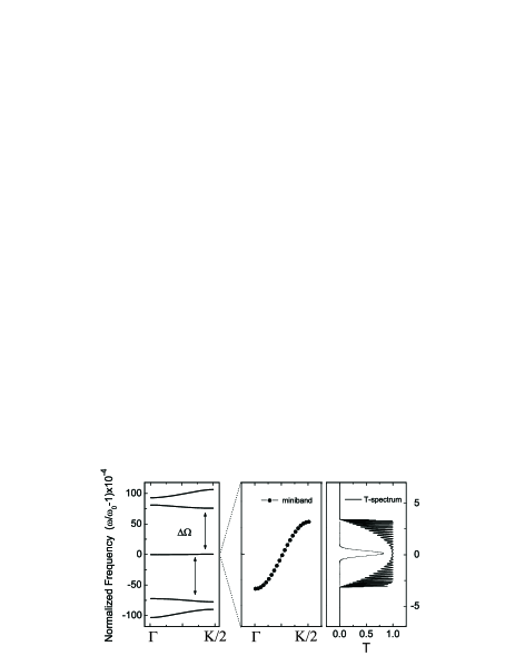
A CROW is a spatially periodic many-cavity system, in which the degeneracy of the resonant states is lifted by the coupling between neighboring cavities. As a result, a miniband is created (see Figure 1), with a dispersion law whose width is proportional to the coupling strength coupledcav and whose group velocity is orders of magnitude lower than the one associated to the average refractive index of the structure. This is a consequence of the strong light localization in the cavity states. For example the group velocity at the center of the miniband shown in Figure 1 is two order of magnitude smaller than the vacuum light speed.
In a infinite CROW system the discrete translational symmetry of period guarantees that the quasi-wavevector (defined modulo integer multiples of the reciprocal lattice vector ) is conserved under any refractive index modulation which preserves the discrete translational symmetry. A time-dependence in the refractive index will give a time dependence of the dispersion law. Provided the electromagnetic field dynamics is limited to the miniband states only, the frequency of the wave is fixed by the miniband dispersion law. Thus the change in the refractive index results in a corresponding change of the carrier frequency of the wavepacket.
There is a basic limitation to the maximum speed at which the refractive index can be changed. Indeed, to preserve the coherent information, the pulse should remain in the miniband during the whole process. This is the case provided that the refractive index tuning is adiabatic Galindo . As an estimate, the tuning time should be much larger than the inverse of the minimum frequency separation between the miniband and the nearest allowed photonic states, shown schematically in Figure 1.
In a finite CROW system, for which the impedances are carefully matched at the input and output interfaces, the central part of the miniband corresponds to a frequency window in the transmittivity, which is flat and almost unity, Figure 1. The travel time is fixed by the group velocity flatvg . The transmittivity profile guarantees that an incident pulse, whose energy dispersion resides in the flat part of the spectrum, penetrates and crosses the photonic structure without significant distortion. The strong reduction of with respect to implies a much looser bound on the system length in order to be able to perform the refractive index modulation while the pulse is contained in the structure.
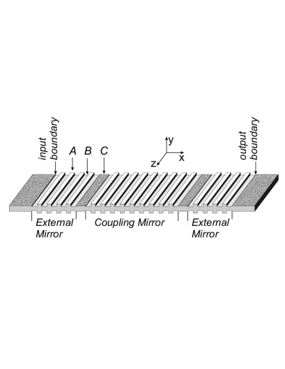
In order to illustrate the idea, we perform Finite Difference Time Domain (FDTD) simulations of a pure one-dimensional (1D) structure composed by 45 Fabry-Perót microcavities, coupled to each other through 27-period Distributed Bragg Reflectors (DBRs). The mirrors and the cavities are constituted by quarter- and half-wavelength layers, respectively, and are centered at nm. Moreover the input-output mirrors are suitably designed in order to have a good impedance matching between the finite-1D photonic structure and input/output channels (see Figure 2). Assigning letters and to the mirror layers and to each cavity layer, we choose their refractive indices equal to , and , respectively. The choice of these values is due to the realistic implementation with the available silicon technology we suggest in the second part of this Letter.
The time dependence of the structure in the simulation consists in a relative shift of the refractive index, applied to the whole structure, triggered after the injection of the pulse and completed before the pulse exits. For simplicity, a linear time dependence of has been considered. The number of microcavities has been determined assuming that the index change can be completed within 20 ps. Consistently, the minimum tuning time for being adiabatic is, for our parameters, much smaller, of the order of 10 fs. The final device length is about 370 m. A switching time longer than 20 ps would simply imply a proportionally longer structure. A value has been chosen on the basis of realistically attainable values in semiconductor technology electropticmaterials . It is worth noticing that significantly larger index shifts, hence, frequency tuning, would be possible, just by resorting to electro-optic materials such as LiNbO3 electropticmaterials .
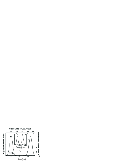
The FDTD simulation of the pulse transport is reported in Figure 3. The output signal (solid line) is plotted versus both time and its relative delay to the travelling time () of a pulse travelling in a structure with the same length, but consisting of a single homogeneous layer with the average refractive index of our structure. The pulse delay is 116 ps, which is larger by a factor of compared to the homogeneous case. The resulting vacuum wavelength shift nm is shown in the inset, and corresponds to the expected value (). Finally, as expected, the distortion of the input pulse is negligible and the efficiency of conversion is larger than 95%.
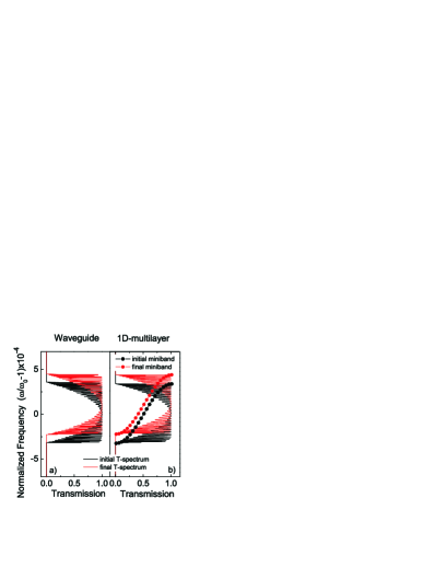
A realistic implementation of the photon energy lifter with available standard technology is based on silicon waveguides. Moreover, as it will become clear later, such a system can be suitably described by the 1D system previously used and analyzed to illustrate the photonic energy lifter principle. The typical architecture of a silicon waveguide working in the infrared range is composed by a silicon guiding layer of about 260nm thickness, sandwiched between SiO2 cladding layers. The index contrast between the two materials assures light confinement in the silicon core. The photonic structure (DBRs and cavities) can be realized modulating the thickness of the silicon slab, which corresponds to an effective refractive index modulation of the fundamental transverse mode, Figure 2. We perform, using an eigenmode expansion method sudbo , a full two dimensional simulation for the slab waveguide before and after the index switching. For the sake of computational simplicity, as sketched in Figure 2, we assume a vertical symmetric (the -direction) architecture. The physical parameters of the integrated device (length and thickness of the layers) – which eventually provide the refractive indices used in the 1D FDTD – have been chosen in order to maintain a good modal matching between input/output waveguides, cavities and DBRs. In this way the insertion losses in the resulting two dimensional CROW slab device appear to be negligible, of the order of dB. In Figure 4 both initial and shifted miniband spectra of the slab structure (panel (a)) and the 1D model of the CROW (panel (b)) are shown. The agreement is quite satisfactory, confirming that the 1D structure (and the 1D FDTD code) is a good description for the waveguide system.
Up to now the basic idea of the photon energy lifter was based on the hypothesis that the refractive index can be simultaneously changed in the whole structure while the pulse is travelling across it. Another possible scheme, which can simplify the experimental realization is what can be called a travelling-wave design tavellingwave . In this scheme, the electrical field for the electro-optic effect is not applied simultaneously to the whole device, but is injected as a microwave from one end of the electrode pair. Electrodes work as a transmission line. In this design, the electrode capacitance, being distributed, does not limit the modulator speed, and the electrodes can be made very long.
Since the photonic structure under study is designed for optical wavelengths, it behaves as a homogeneous medium at microwaves. Therefore, it is expected that the group velocity at microwaves is determined by the average refractive index, , of the structure and thus it is much higher than the group velocity of the optical pulse. Moreover, the considered pulse wavelength, being much shorter than that of the microwave, sees an almost translational invariant system with a time-dependent refractive index.
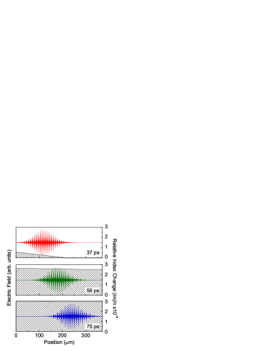
We assume, for our FDTD simulations, a conservative value of =3 as the effective refractive index of the mixed Si/SiO2 structure at microwaves. Therefore the optical in our structure is lower than the microwave group velocity by over an order of magnitude. The microwave driver signal is taken as a smooth function with GHz. The microwave is sent into the structure with a 35 ps delay from the input light signal, i.e., when the injection of the light signal is essentially completed Figure 3. Sample electric field snapshots resulting from the combined optical and microwave simulations are reported in Figure 5, where an instantaneous correspondence of the microwave amplitude with the relative refractive index change has been assumed. The results of the travelling-wave simulation are not distinguishable from the results of Figure 3, which validates this method.
A more practical travelling wave design would consider a device architecture where the light is also laterally confined (along the direction in Figure 2), e.g., a so-called ridge waveguide.
In conclusion, we have proposed a novel photonic device which is able to shift the carrier frequency of an optical pulse without affecting its shape. This is obtained by changing in time the refractive index of a coupled-cavity system while the pulse is propagating through the structure and is fully contained in it: the low value of the group velocity in coupled-cavity systems is a key ingredient for this procedure to be possible in a miniaturized device. Full numerical simulations have been used to confirm our predictions for realistic silicon-based systems with different switching mechanisms.
In addition to the strong technological interest of the present proposal for a photon energy lifter, it is another example of the intriguing properties that electromagnetic waves have when travelling in a time-dependent photonic structure.
We acknowledge the financial support by MIUR through FIRB (RBNE01P4JF and RBNE012N3X) and COFIN (2004023725) projects and by PAT through PROFILL project.
References
- (1) O. Boyraz and B. Jalali, Opt. Exp. 12, 5269 (2004); H. Rong et al, Nature 433, 292 (2005); H. Rong et al, Nature 433, 725 (2005).
- (2) E. J. Reed, M. Soljačić, and J. D. Joannopoulos, Phys. Rev. Lett. 90, 203904 (2003).
- (3) M.F. Yanik, W. Suh, Z. Wang, and S. Fan, Phys. Rev. Lett. 93, 233903 (2004); M.F. Yanik and S. Fan, Phys. Rev. A 71, 013803 (2005); M. L. Povinelli, S. G. Johnson, J. D. Joannopoulos, Opt. Express 13, 7145 (2005).
- (4) Single optical microcavity can localize strongly the light cavities and, in principle, are suitable for changing the photon energy. However, these structures strongly distort pulses.
- (5) K.J. Vahala, Nature 424, 839 (2003); B.S. Song, S. Noda, T. Asano and Y. Akahane, Nature Materials 4, 207 (2005).
- (6) H. Gersen et al., Phys. Rev. Lett. 94, 073903 (2005).
- (7) see, e.g., A. Melloni, F. Morichetti, and M. Martinelli, Optics & Photonics News 14, 44 (2003); J. Scheuer, G.T. Paloczi, J.K.S. Poon and A. Yariv, Optics & Photonics News 16, 36 (2005).
- (8) H. Altug and J. Vukovi, Appl. Phys. Lett. 86, 111102 (2005).
- (9) M. Ghulinyan et al., J. Appl. Phys. 93, 9724 (2003).
- (10) A. Galindo and P. Pascual, Quantum Mechanics II, (Springer, Berlin, 1991).
- (11) Y.-H. Ye et al., Phys. Rev. E 69, 056604 (2004).
- (12) see, e.g. C.R. Pollock, Fundamentals of Optoelectronics (Irwin, Chicago, 1995).
- (13) A.S. Sudbo, IEEE Phot. Technol. Lett. 5, 342 (1993).
- (14) R.C. Alferness, Science 234, 825 (1986).