Dynamics of stripe patterns in type-I superconductors subject to a rotating field
Abstract
The evolution of stripe patterns in type-I superconductors subject to a rotating in-plane magnetic field is investigated magneto-optically. The experimental results reveal a very rich and interesting behavior of the patterns. For small rotation angles, a small parallel displacement of the main part of the stripes and a co-rotation of their very ends is observed. For larger angles, small sideward protrusions develop, which then generate a zigzag instability, ultimately leading to a breaking of stripes into smaller segments. The short segments then start to co-rotate with the applied field although they lag behind by approximately . Very interestingly, if the rotation is continued, also reconnection of segments into longer stripes takes place. These observations demonstrate the importance of pinning in type-I superconductors.
pacs:
PACS numbers: 74.76.Db, 74.60.Ge, 74.25.Dw, 74.60.Jg,74.25.FyType-I superconductors have been studied quite extensively since their discovery and until the 60s. Even though the formation of patterns in the intermediate state was observed by different techniques huebener , little attention was paid to the dynamic properties of this modulated phase. In this work we focus on the experimental study of the dynamics of stripe patterns in the intermediate state of type-I superconductors. A thin sheet of type-I material in a magnetic field perpendicular to its large surface is in the IS for a certain range of temperatures and magnetic fields. In this state, alternating normal (N) () and superconducting (SC) (B = 0) macroscopic regions are formed in the sample. This modulated phase is a consequence of the competition between the magnetic energy that favors the formation of small domains and a positive SC-N interface energy that tends to form large domains. It is well known sharvin that straight laminae of SC and N domains are formed when the sample is cooled in a magnetic field with non-zero in-plane component, (Sharvin geometry). The laminae are extended along the direction of , with period and width determined by the applied field and the sample thickness. R. Goldstein et al. goldstein2 ; goldstein1 developed the theoretical current loop model to explain the formation of patterns in type-I superconductors. They consider the IS as a collection of current ribbons flowing along the SC-N interfaces. Even though the magnetic energy is treated only approximately narayan the model reproduces the results of the Landau model for straight laminae landau . Instabilities of the laminar state in type-I superconductors are expected goldstein2 similarly to other systems. For example, an Eckhaus instability eckhaus should appear when the field changes slowly due to rearrangement of the laminae width and period to the new equilibrium condition. In convective systems, croquette ; lowe this instability leads to a smooth movement of dislocations. In addition, it was predicted goldstein2 that a zigzag pattern is induced in the IS of a type-I superconductor if is rotated with respect to the direction of the laminae.
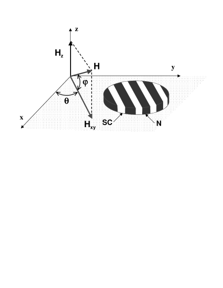
We study the response of a stripe pattern in a type-I superconductor to a change of in-plane field direction. The sample was obtained by flattening a Pb foil down to a thickness of 0.15 mm and by cutting it to a lateral dimension of cm. The sample was annealed at C to remove stress induced by flattening and cutting. We present experiments made in a square sample but equivalent results were obtained in a circular shaped one. Magneto-optical images were acquired using the technique described in wijngaarden which yields maps of the local magnetic induction just above the surface of the sample. The sample is mounted in a Oxford Instruments 7T vector magnet system that allows to change independently 3 perpendicular components of the magnetic field. We define as the angle between the projection of the field in the xy plane () and the x-axis and as the angle between the total field vector and , see Fig. 1. The experiments are performed as follows. First, an ordered stripe structure is obtained at 6 K by decreasing from large values such that the sample is in the normal phase, down to 26 mT while is fixed at 2 mT. These values correspond to and . Subsequently, is changed in steps of at a rate of sec while is kept constant. A typical initial pattern is shown in Fig. 2(a). Similar structures are obtained if the IS is reached decreasing at constant or by decreasing temperature at constant .
In the initial state (, Fig. 2(a)) some dislocations in the form of stripes that end in the interior of the sample are observed. This is a consequence of a stripe period re-adjustment when decreasing the (in-plane) field. The energy of a dislocation is found to be very small goldstein2 indicating that, as we observe experimentally, it is easy to nucleate this type of defects in the IS of type-I superconductors. As in the case of convective systems croquette ; lowe , the formation of edge dislocations is a consequence of an Eckhaus instability.
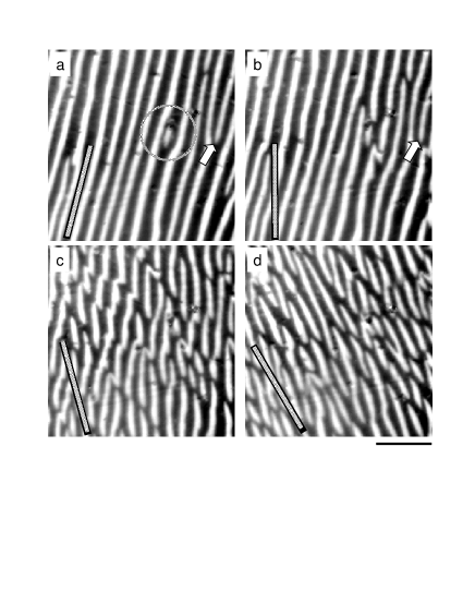
Up to (Fig. 2(b)) the pattern remains quite ordered and the stripes are mostly parallel to the initial direction (). It is also evident that the rotation has induced the breaking of a few stripes. New free-ends of stripes are formed in regions where the laminae are already distorted in the initial state, see the encircled region in Fig. 2(a). The free-ends are oriented along while the rest of the stripe remains locked at . This suggests that the extra surface energy when breaking the stripe is compensated by the energetic gain of orienting it parallel to . Consistently, some of the already present free-ends in the initial pattern (see arrows in Fig. 2(a) and (b)) also align with the in-plane field for . Also the ends of the stripes at the edge of the sample (not shown) show a tendency to follow the actual field direction, while the remaining portion of the stripes are locked at .
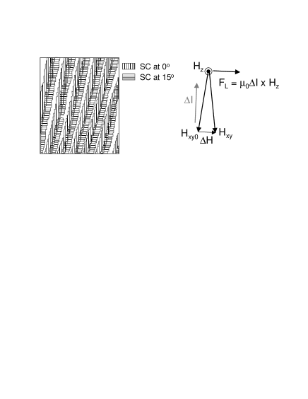
Besides the disorder induced by the reorientation of stripe-ends when rotating over , a small net displacement of the structure is also observed, see left panel of Fig 3. Vertical-dashed (horizontal-dashed) regions indicate the stripes in the structure at (). A change in the direction of the in-plane field component induces currents that flow on the top and bottom surfaces of the sample. The Lorentz force associated with these screening currents causes the translation of stripes as observed by MO experiments on the top surface (Fig. 3, right panel). On the bottom surface the force has opposite sign (since the current flows in opposite direction), leading to a shear deformation of the stripes. Thus, the main effect of the rotation in this first stage is a shear of the laminae along the sample thickness detected as a translation motion on the top surface. This induced Lorentz (shear) force is acting on the stripes during the whole rotation experiment. However, its effect is more evident at the beginning. At a later stage, the dynamics of the stripes is rather complex making the observation of the translation motion more difficult.
If the angle of rotation increases to (Fig. 2(c)), in some regions zigzag-like structures are formed in agreement with theoretical prediction goldstein2 . Surprisingly, cutting of some long stripes is also observed giving rise to the formation of short SC segments. Finally, at (Fig. 2(d)) the pattern consists of short segments, either straight or s-shaped. It is interesting to note that if is turned back to is not possible to recover the same pattern as at the beginning of the experiment. Instead, a more disordered structure remains that has higher energy than the originally ordered one. If the rotation is stopped at a certain angle and the external parameters are kept constant no significant changes in the structure are observed over a long time ( hour). These two results indicate that after the rotation, the system is in a local minimum of energy with very large relaxation time constant. This implies significant energy barriers induced by the pinning potential in the sample.
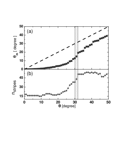
In order to investigate how the patterns follow the in-plane field direction we calculate the average direction of the pattern, , from the average orientation of the peaks in the Fourier transform of the images. The results of this calculation are shown in Fig. 4(a). The dashed line corresponds to the condition that the pattern is parallel to and the square symbols are the experimental values. As we have mentioned, at small angles , the orientation of the structure is locked at the direction defined by the initial . At larger angles, the mean direction changes as the stripes try to follow the in-plane field and at a rapid increase is observed. In order to find the origin of this jump in we calculate the number of segments, , as a function of the angle of rotation (see Fig. 4(b)). Clearly, at there is also a rapid increase of indicating that the improved alignment of the structure is related with the breaking of many stripes. At and also small jumps in are observed. However, in those cases there is no significant change in . Here the realignment is made by rotation of the already short segments. Thus, we find that the mechanism for alignment of the stripes with the direction of the in-plane field is: cutting of stripes followed by rotation of short segments.
From the present experimental results it is clear that pinning plays an important role in the dynamics of these structures. The stripes remain locked at the initial direction, even when the direction of is changed by . This is not due to the stripes being locked by extended defects, because when is reached and the rotation continues thereafter, no lock-in of the structure is observed. In addition, when the experiment is repeated under the same conditions, the stripes do not nucleate in exactly the same positions, nor do they return to the same positions when the field is first rotated to say and subsequently to . In the last case, always a kind of ”backlog” is observed. We conclude that pinning is important and that it is the result of many small defects acting together. When the structure is nucleated, the system takes as much profit as possible from the pinning sites. As the angle of rotation increases there is an increase in the magnetic energy due to misalignment with the external field. At a certain moment, the stripes start to break and rotate, while being still partially pinned: now they are in a metastable state and do not profit fully anymore from the energy lowering by pinning.
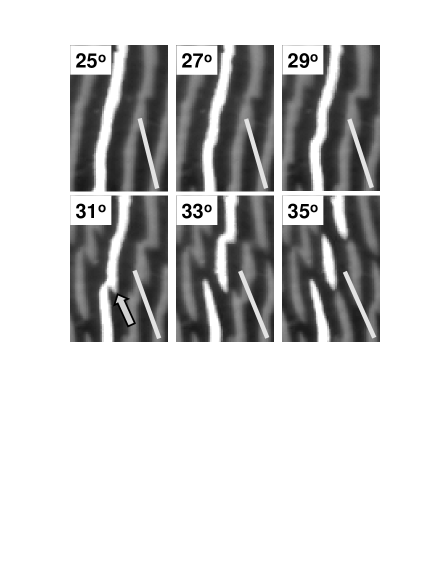
In Fig. 5 we show the evolution of one SC stripe (highlighted) as the direction of changes such that the process of zigzag formation and subsequent cutting of stripes can be observed. The straight lines indicate the direction of . At the segment is misaligned with respect to by . As increases to the segment bends. Then, the undulations of the stripe become sharper giving rise to the onset of a zigzag structure (). At the stripe breaks in the lower part while at approximately 1/3 of its original length a clear zigzag is observed. Finally, at the line breaks also at that point and the lowest and highest segments are reasonably aligned with the actual while the middle segment is misaligned by about . In subsequent images (not-shown) the middle segment also rotates in response to the change in . Apparently, a zigzag is an intermediate structure formed prior to the cutting of stripes. The zigzags seem to be initiated by small sideward protrusions to the stripes (see arrow in the image at ), which have roughly the same period (measured in the direction normal to the actual ) as the original stripes. These protrusions can be seen as new laminae growing parallel to the actual from the existing laminae. However, before the protrusions become very large, the original laminae break and their ends turn in the direction of the actual field, thereby absorbing the protrusions. As soon as the laminae break, the applied field generates a torque on the new-free ends promoting their rotation and consequent alignment with (see the image at in Fig. 5). This torque also induces s-shaped deformed segments. Similar effects have been observed in chains of magnetic nanoparticles subjected to a rotating magnetic field melle .
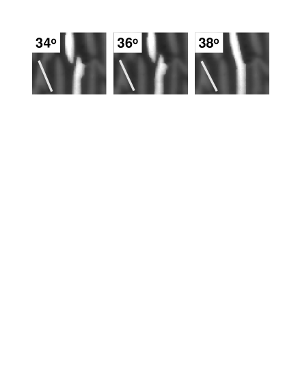
The inhomogeneous distribution of magnetic field inside the sample implies the presence of currents at the SC-N interface (that shield the magnetic field from the SC regions). Hence, the cutting of stripes implies that neighboring regions (at the new free-ends of stripes) with currents flowing in opposite directions are formed. Considering only interaction between currents, the stripe-ends repel each other. Thus, in this simple picture, reconnection of stripes is unexpected. However, we do observe reconnection of SC stripes, see Fig. 6. This suggests that the forces associated with the interface energy and magnetic energy are able to overcome the repulsion between the currents. We have also observed that the locations in the sample where the cutting and reconnection takes place are not reproducible. Therefore we can rule out that these events are induced by irregularities or static defects in the sample.
Very recently, numerical simulations of the response of stripes in a magnetic system subjected to a rotating in-plane field were performed jaglaprivate . The preliminary results show that the stripe domains first cut and later partially reconnect while the field is rotating, as observed in our experiments. Since the same model of simulations reproduces various patterns formed in type-I superconductors jaglapre it is reasonable to think that the cutting and reconnection of stripes is an intrinsic behavior of a stripe pattern subjected to a rotating field.
The results presented in this article show that the evolution of a stripe pattern subject to a rotating field is more complex and rich than expected. At small rotation angles the whole structure (except at the edges of the sample) is locked at the direction fixed by the initial condition. In this regime, there is only a shear of the stripes along the thickness of the sample due to the currents induced by the change in direction. The corresponding Lorentz force is due to surface currents and hence acts mainly on those parts of the stripes that are in contact with the sample surface. The bulk of the stripe is, however, free from this Lorentz force. As a consequence, a small shear of the stripe can happen rather easily (large Lorentz force/pinning force ratio), while rotation of a complete stripe involves the bulk pinning force on the whole stripe and is much more unfavorable (small Lorentz force/pinning force ratio). Hence, we observe first a shift of the stripes and only at later stage the rotation starts. Subsequently, a bending of stripes and a zigzag instability, in agreement with the theoretical expectation goldstein2 , is observed. As the angle of rotation increases, cutting and reconnection of stripes is detected. The rotation of the stripes is the result of the balance between the torque due to the misalignment of the stripes with respect to the applied field and the pinning force. Our experimental results indicate that a delicate balance between all the terms in the energy determines the response of a stripe structure to a rotating field. In particular, it is evident that pinning plays an important role. This brings up a new challenge in the understanding of the dynamics of modulated phases and a more stringent test for current string models for type-I superconductors.
Acknowledgements.
This work was supported by FOM (Stichting voor Fundamenteel Onderzoek der Materie) which is financially supported by NWO (Nederlandse Organisatie voor Wetenschappenlijk Onderzoek).References
- (1) R. P. Huebener, Magnetic Flux Structures of Superconductors (Springer-Verlag, New York, 1990).
- (2) Y. V. Sharvin. Soviet Phys. JETP 6, 1031 (1958).
- (3) A. T. Dorsey and R. E. Goldstein, Phys. Rev. B 57, 3058 (1998).
- (4) R. E. Goldstein, D. P. Jackson and A. T. Dorsey, Phys. Rev. Lett. 76, 3818 (1996).
- (5) O. Narayan, Phys. Rev. Lett. 81, 5035 (1998); A. T. Dorsey and R. E. Goldstein ibid. 81, 5036 (1998).
- (6) L. D. Landau, Soviet Phys. JETP 7, 731 (1937).
- (7) W. Eckhaus, Studies in Nonlinear Stability Theory (Springer-Verlag, New York, 1990).
- (8) V. Croquette, Contemp. Phys. 30, 113, 153 (1989).
- (9) M. Lowe and J. P. Gollub, Phys. Rev. Lett. 55, 2575 (1985).
- (10) R. J. Wijngaarden et al., Rev. Sci. Instrum. 72, 2661 (2001).
- (11) S. Melle et al., Phys. Rev. E 68 041503 (2003).
- (12) E. A. Jagla (private communication).
- (13) E. A. Jagla, Phys. Rev. E 70, 046204 (2004).