Spin-Polarized Current Induced Torque in Magnetic Tunnel Junctions
Abstract
We present tight-binding calculations of the spin torque in non-collinear magnetic tunnel junctions based on the non-equilibrium Green functions approach. We have calculated the spin torque via the effective local magnetic moment approach and the divergence of the spin current. We show that both methods are equivalent, i.e. the absorption of the spin current at the interface is equivalent to the exchange interaction between the electron spins and the local magnetization. The transverse components of the spin torque parallel and perpendicular to the interface oscillate with different phase and decay in the ferromagnetic layer (FM) as a function of the distance from the interface. The period of oscillations is inversely proportional to the difference between the Fermi-momentum of the majority and minority electrons. The phase difference between the two transverse components of the spin torque is due to the precession of the electron spins around the exchange field in the FM layer. In absence of applied bias and for a relatively thin barrier the perpendicular component of the spin torque to the interface is non-zero due to the exchange coupling between the FM layers across the barrier.
The effect of current-induced switching on the orientation of magnetic moments in magnetic heterostructures has recently attracted significant interest due to its potential applications to spin electronics Myers ; Krivorotov , such as current-controlled magnetic memory elements. When a current of spin polarized electrons enters a ferromagnet, there is a transfer of angular momentum between the propagating electrons and the background magnetization of the layer. The concept of switching the orientation of a magnetic layer of a multilayered structure by the current perpendicular to the layers was originally proposed by Slonczewski Slonczewski and Berger Berger , and has been followed by others Ralph ; Stiles . This effect, often referred to as “spin torque”, may, at sufficiently high current densities, alter the magnetization state. An alternative mechanism of current-induced switching was put forth by Heide et al Heide and Zhang et al Levy in which the current across the magnetically inhomogeneous multilayer produces spin accumulation which establishes an energy preference for a parallel or antiparallel alignment of the moments of the magnetic layers.
The purpose of this work is to employ a one-dimensional single-band tight-binding model and calculate the spin torque in magnetic tunnel junctions consisting of two ferromagnetic layers (FM) with non-collinear orientation of the magnetization, separated by an insulating (I) thin layer. The calculations are carried out using the non-equilibrium Green’s function technique in the framework of the Keldysh formalism Caroli . We have calculated the spin torque using two different approaches: the first uses the local magnetic moment of the conduction electrons and the exchange splitting of the -band; the second uses the divergence of the transverse component of the spin current. The results demonstrate that these two approaches are equivalent, as hypothesized originally by Edwards et al Mathon .
The method for calculating the non-equilibrium Green functions for the non-collinear system is a generalization of that introduced by Caroli et al Caroli for nonmagnetic leads, where one replaces the Green functions with 22 matrices in spin space. For this purpose we divide the Hamiltonian into two parts: one which describes the spin-average medium and the other proportional to the spin splitting of the band structure, i.e.,
| (1) |
Here, the subscript indexes indicate the atomic sites, the superscript indexes refer to spins, and and denote the spin-dependent on-site energy and nearest-neighbor hopping matrix elements, respectively. The one-electron Shrödinger equation becomes
| (2) |
where is the retarded Greens function for the isolated semi-infinite leads, is the angle between the magnetizations of the FM leads in the plane perpendicular to the current, and is 22 unit matrix. Following Caroli Caroli , we next calculated the retarded Green function for the entire system. Finally, by solving the kinetic equation we evaluated the non-equilibrium Green function .
Having calculated the , the effective local magnetic moment on site in the right FM lead can be obtained from it by
| (3) |
where is the Pauli matrix vector. The spin current is given by
| (4) |
where is the hopping matrix element in the right lead.
We model the FM/I/FM junction with , , for the FM leads, and , for the insulating layer Mathon2 . The insulator consists of five layers. We assume that the potential drop is confined to the barrier and is linear within the barrier. We have calculated the torque from
| (5) |
where is the exchange field along the z-direction, and, alternatively, from the divergence of the spin current
| (6) |
In Fig.1 we show the spatial distribution of the components of the spin torque on the right FM lead that are perpendicular () and parallel () to the plane of the layers for . These are calculated both via the local magnetic moment approach using equation (5) (solid and dashed curves) and via the divergence of the spin current from equation (6) (solid and open symbols). The direction of eletron flow is from the right to the left FM lead.
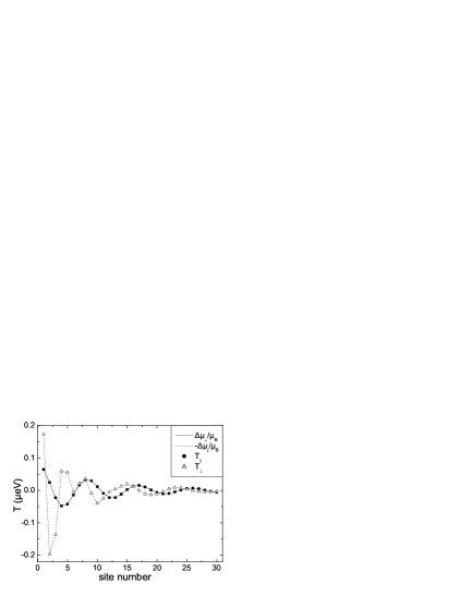
One can see that both methods are equivalent giving identical results for the spin torque, i. e. the absorption of the spin current at the right FM electrode is equivalent to the exchange interaction between the electron spins and the local magnetization. This equivalence is valid for an arbitrary angle between the magnetization of FM layers. The angular dependence of the spin torque is proportional to .
Both and components of the spin torque oscillate with different phase and decay with distance in the FM layer from the right FM electrode. The period of oscillations is inversely proportional to the difference between the Fermi-momentum of spin-up and spin-down electrons. The phase difference between the two components of the spin torque is due to the precession of the electron spins around the exchange field in the FM layer. The components and of the effective magnetic moment are referred to by previous studiesHeide ; Levy as “spin accumulation”. We find that in general, and are comparable in magnitude and they can be of the same or opposite sign depending on the position in the right FM electrode.
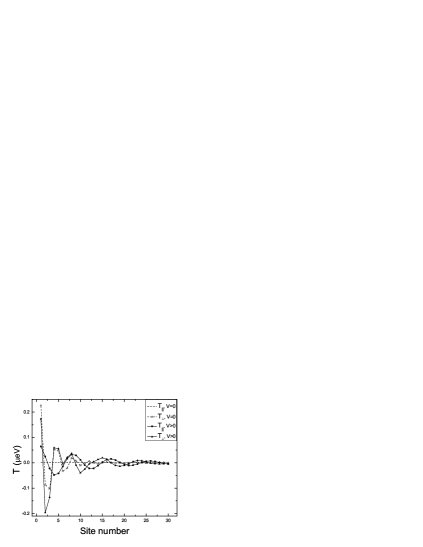
In Fig. 2 we show the spatial distribution of the parallel and perpendicular components of the spin torque at zero and finite bias. At zero bias, while , indicating that plays the role of the exchange coupling between the FM leads across the barrier Tiusan . At finite bias, the role of current-induced spin torque is played by and . The exchange coupling explains irregular oscillations of in Fig. 1 and Fig. 2 at finite bias close to the interface. Since it decays rapidly with the distance from the interface (see Fig. 2, at ), the oscillatory behaviour of becomes normal again in the bulk of the FM layer.
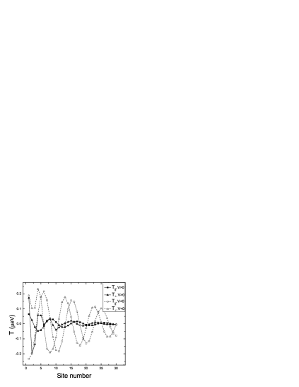
So far we have discussed the spin torque behaviour for the case of positive applied bias, i.e. when electrons flow from the right FM electrode to the left one. We consider the spin torque in the right FM electrode, where the magnetization orientation was chozen to be along the axis. In this case, only those electrons reflected from the left interface are polarized transversly to the magnetization of the right FM layer thereby contributing to the current induced spin torque. The situation changes drastically when one reverses the current flow, i.e. at negative bias. The majority of electrons transmitted from the left FM layer into the right one are transversely polarized and lead to a significant increase of the current induced spin torque. Both situations are demonstrated in Fig. 3, where and are plotted for positive and negative applied bias.
The research at California State University, Northridge was supported from NSF under Grant No DMR-00116566 and US Army under Grant No AMSRD-45815-PH-H .
References
- (1) E.B. Myers, D.C. Ralph, J.A. Kattine, R.N. Louie, R.A. Buhrman, Science, 285, 867 (1999).
- (2) I.N. Krivorotov, N.C. Emely, J.C. Sankey, S.I. Kisilev, D.C. Ralph, R.A. Buhrman, Science, 307, 228 (2005)
- (3) J.C. Slonczewski, J. Magn. Magn. Mat., 159, L1 (1996).
- (4) L. Berger, Phys. Rev. B, 54, 9353 (1996).
- (5) X. Waintal, E. B. Myers, P. W. Brouwer, D. C. Ralph, Phys. Rev. B 62, 12317 (2000).
- (6) M.D. Stiles, A. Zangwill, Phys. Rev. B, 66, 014407 (2002).
- (7) C. Heide, P. E. Zilberman, and J. R. Elliot, Phys. Rev. B 63, 064424 (2001).
- (8) S.Zhang, P.M. Levy, A. Fert, Phys. Rev. Let., 88, 236601 (2002).
- (9) C. Caroli, R. Combescot, P. Nozieres, D. Saint-James, J. Phys. C: Solid St. Phys., 4, 916 (1971).
- (10) E.D. Edwards, F. Federici, J. Mathon, A. Umerski, Phys. Rev. B, 71, 054407 (2005).
- (11) H. Itoh, J. Inoue, A. Umerski, J. Mathon, Phys. Rev. B., 68, 174421 (2003).
- (12) J. Faure-Vincent, C. Tiusan, C. Bellouard et al., Phys. Rev. Lett., 89, 107206 (2002).