Electrical driving single barrier spin cell
Abstract
We propose a spin cell based on photon-assisted tunneling through a conventional semiconductor barrier. The Dresselhaus spin-orbit interaction is included to break the spin rotation symmetry. Due to the in-plane electric field induced asymmetric momentum distribution in one lead, continuous flows of spin currents are driven through a barrier by a AC field. The net charge current remains zero. The spin current via photon-assisted tunneling can be readily adjusted via tuning the AC frequency or the in-plane electric field. This device may function as an ideal spin cell to supply spin currents in the spintronics circuit.
In recent years, an emerging technology named spintronics has attracted much attention (for review, see Science2941488 ; RMP76323 ). The motion of spin-polarized electrons produces a spin-dependent particle currentScience2941488 ; PRL90258301 . To form a complete spintronics circuit, it is vital important to have a spin cell which supplies continuous spin current through the circuit. Recently, such a spin cell was proposed based on the AC-driven double-dot system in a spatially nonuniform external magnetic fieldPRL90258301 . This spin cell can provide a spin current without a charge current by carefully adjusting the device parameters. However, this spin cell met with some challenges such as the nonuniform magnetic field. An efficient non-magnetic spin cell is thus extremely desirable. The spin-orbit interaction due to inversion asymmetryRMP76323 provides us the possibility to construct an electrical driving spin cell based on the conventional semiconductors.
In this work, we propose an electrical driving single barrier spin cell, where the Dresselhaus spin-orbit interaction in a confined region is employed to break the spin rotation symmetry. A continuous flow of spin current is generated when the isotropic momentum distribution of electrons is broken by an in-plane electric field, while the net charge current remains zero. By applying an AC field, the spin current can be greatly enhanced via photon-assisted tunneling and the spin injection can be readily adjusted via tuning the AC frequencies or the in-plane electric field. A tunable electrical driven spin cell can be achieved.
The model device is illustrated in Fig. 1. The device consists of a piece of zinc blende semiconductor potential barrier which is confined by two ideal (free of charge and spin interaction) conducting leads. The central region and the two leads are connected via tunneling. Let the growth direction along direction. The coordinate axes , and are set to be parallel to the cubic crystallographic axes [0,0,1], [1,0,0], and [0,1,0]. The wave vector of electrons is , where is the in plane wave vector and is the wave vector along the growth direction. We assume a perfect match at the interfaces of the device, where is a good quantum number. The Hamiltonian can thus be diagonalized in the basis . The central barrier we are interested is an open system where electrons can flow back and forth between the barrier and the two leads. The dynamics of this open system can be well described by an effective non-Hermitian Hamiltonian PRC6114 : , where is the Hamiltonian of the central barrier and the non-Hermitian term includes all the boundary conditions such as the barrier-lead coupling. By taking the assumption that the incident electron’s kinetic energy is much smaller than the height of the barrier potentialPRB67201304 , the central Hamiltonian of the zinc blende semiconductor is then given in the nearest neighbor tight-binding approximationDatta by
where contains all the on site energies at (), is the discrete lattice constant, is the nearest neighbor hopping matrix element, is the Dresselhaus constant of the chosen material, and () creates (annihilates) a spin electron at site with a given parallel wave vector . In the wide band approximation and symmetric coupling, the non-Hermitian part of Hamiltonian has the form , where is the energy independent level width function.
For a high barrier height, the electron transmission probability is greatly reduced by the nonresonant tunneling process. We apply an AC field to achieve a tunable spin cell via photon-assisted tunnelingPR3951 ; PRL90210602 . Suppose the junction is illuminated by a monochromatic AC field of frequency . The on-site energies of the barrier are modified by the AC field. The total Hamiltonian is written as , where .
In this work, we generalize the Floquet-Green formalismPRL90210602 to the spin-involved transport problems. For a given in-plane wave vector , solution of the time-dependent Schrödinger equation in the Floquet ansatz takes the form , where is the quasienergy. The Floquet states can be expanded in Fourier expansion form as . Both the Floquet states and the quasienergies are determined by the eigenvalue equation with a non-Hermitian operator footnote1 . Since the eigenvalues are generally complex, we have to solve the adjoint equation to form a complete biorthogonal basis. The propagation of an electron from site with spin and energy to the state at site and spin under the absorption () or emission () photons is described by the retarded Green function
| (2) |
After obtaining the Green functions, spin-involved transport properties can be described by the 22 -photon assisted transmission matrices and , where the matrix element denotes the time-averaged -photon assisted transmission probability for electrons from the lead to the lead with the initial and final spin state being and respectively. These transmission matrices can be easily obtained by generalizing the result in Ref. PRL90210602 to the present spin dependent transport problem. The diagonal and non-diagonal elements characterize, respectively, the spin-conserved and the spin-flip transport probabilities. Our model has a symmetric design and a standing wave AC potential. The two transmission probabilities are equal since the electron has no way to distinguish the left lead or the right lead. We therefore omit the subscript of the transmission probability as for simplicity.
We apply an external electric field in the - plane in the left lead to create an anisotropic lateral momentum distribution. We assume the central barrier is much higher than the potential caused by the electric field. In the weak electric field limit, the tunneling correction to the distribution function in the lead can be neglected. The difference between the left and the right distribution function in the relaxation time approximation is given byGalp ; JAP87387
| (3) |
where is the transport relaxation time for electrons and is the in plane electron velocity. At low temperature (), the derivative can approximately be replaced by a simple function. The spin current can be found from the time evolution of the spin-resolved occupation number operator and the spin current density (in unit of A/m2) is given by
| (4) |
where the in plane wave vector ( is the polar angle) and the Fermi wave vector are determined by the carrier density in the leads.
We numerically investigated the spin cell model with realistic parameters. We choose the material of central junction to be GaSb which has a larger Dresselhaus constant than other III-V materialsPRB67201304 . The material parameters are given by eVÅ3 and , where is the electron mass. The length of the central junction in our device is Å.The AC potential parameter is fixed at . The Fermi energy of leads and the barrier on site energy are fixed at 0 and , respectively. The carrier density at two leads is set to be cm-3 and the Fermi wave vector is estimated to be m-1. A relaxation time of 1 ps is used in our numerical calculations.
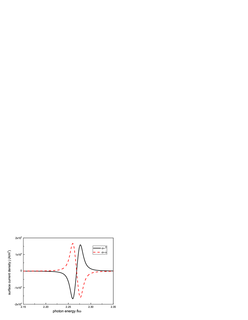
Fig. 2 depicts the surface spin current density as a function of the driving field frequency for a given external in-plane electric field. The in-plane electric field is V/m with the polar angle . The left lead electron distribution in the space is therefore no longer isotropic. From the symmetry properties of our Hamiltonian, we have . Therefore, the spin current densities satisfy the relation: . The two spin currents have the same magnitude but opposite signs. Therefore, the net charge current is always zero. When the frequency of the AC field matches the energy difference between the Fermi energy and the resonant level of the central junction, the spin current reaches its maximum value due to photon assisted tunneling. When the AC frequency is far off the resonant frequencies, the AC pumped spin currents decrease. Due to the spin-orbit interaction, the degeneracy of the lowest resonant level is lifted. One can find two photon-assisted tunneling resonant spin current peaks in Fig. 2. By scanning the frequency across the two resonant frequencies, the spin currents will reverse their direction. Therefore, we can readily control the direction and the magnitude of the spin current of the proposed spin current source by tuning the AC field frequency. If we decouple our device with the external circuit, spin accumulation occurs at the edges of the device due to the balance of spin accumulation and spin relaxation. This spin-accumulation may be experimentally detected by optical techniques based on Kerr/Faraday rotation with submicron spatial resolutionScience3061910 .
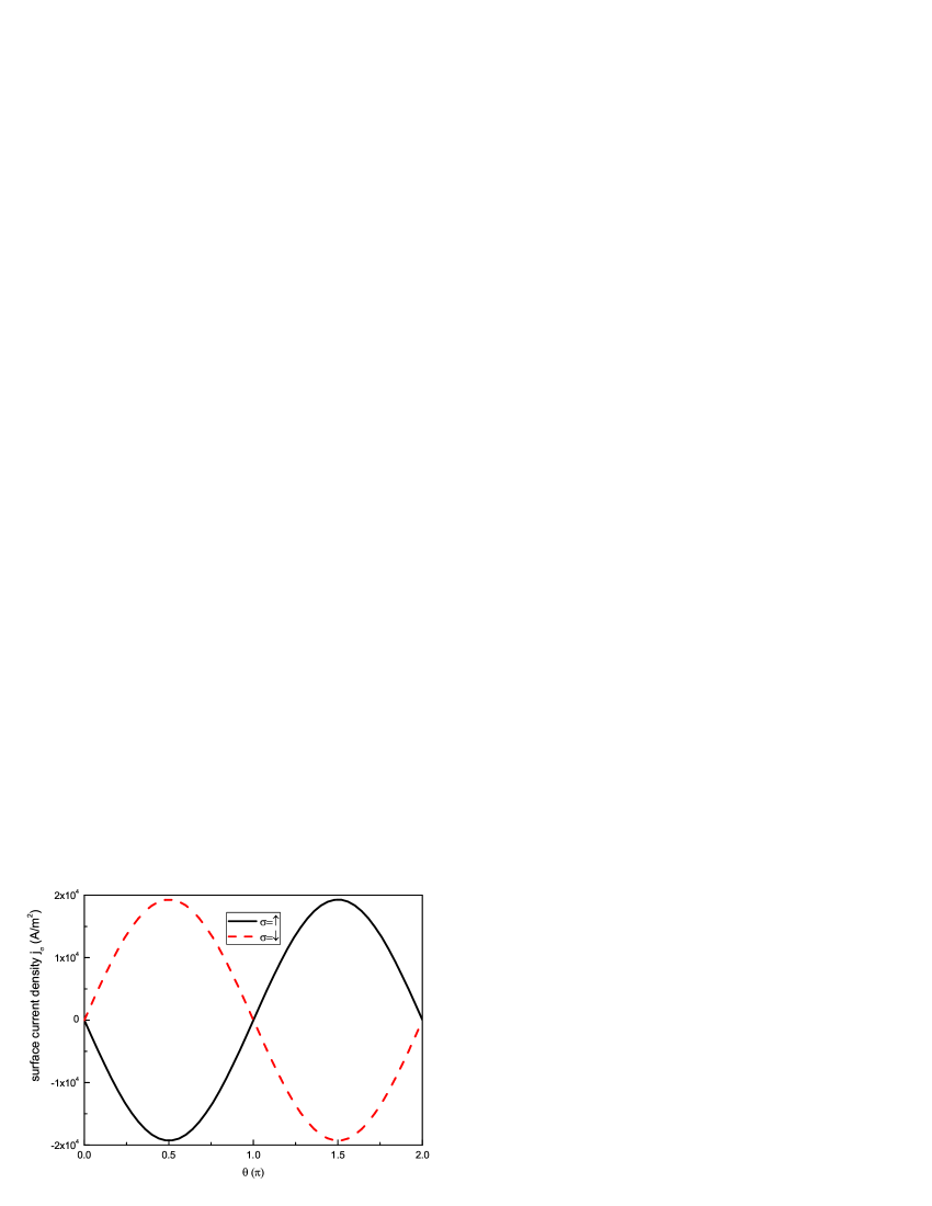
The output spin current can also be tuned by the in-plane electric field. In Eq. (4), the spin current density has a trivial proportion relation with the amplitude of the electric field. However, the polar angle of the in-plane electric field provides us another effective means to control the spin currents. In Fig. 3, we show the numerical calculated surface spin current density as a function of the polar angle of the in-plane electric field. One can see that the spin currents are modulated by in a sinusoidal way. This sinusoidal modulation is caused by the general feature and symmetry of the field induced nonequilibrium distribution and the spin-orbit interaction. We note the spin quantization direction is along axis. From Eq. (4), one can find that is modulated by . For , i.e. the electric field is vertical to the direction (in direction), the spin currents are suppressed to zero. However, when the in-plane electric field deviates from axis, a non-vanishing spin current will be generated. Especially when the electric field is along the axis (), this spin current reaches its maximum.
In conclusion, we have studied an AC driven spin cell by generalizing the Floquet-Green function method. The Dresselhaus spin-orbit interaction due to bulk inversion asymmetry contributes to the spin-dependent effective mass correction and leads to the splitting of the resonant level. Driving the lead electron distribution out of equilibrium by an in-plane electric field, a continuous flow of spin current can be generated by the AC field while the net charge current remains zero. The direction and the magnitude of the generated spin current can be readily tuned by changing the AC frequency or the in-plane electric field direction. Besides all the basic characteristics of spin cell presented in Ref. PRL90258301 , our spin cell functions without external magnetic field or any ferromagnets. It can be operated in a fully electrical way. By integrating our proposed spin cell with spin information processors, one can form a complete spintronics circuit based only on conventional semiconductors.
This work was supported by Korea Research Foundation, Grant No.(KRF-2003-070-C00020).
References
- (1) S. A. Wolf, D. D. Awschalom, R. A. Buhrman, J. M. Daughton, S. von Molnár, M. L. Roukes, A. Y. Chtchelkanova, and D. M. Treger, Science, 294, 1488, (2001).
- (2) I. Žutić, J. Fabian, and S. D. Sarma, Rev. Mod. Phys. 76, 323, (2004); R. H. Silsbee, J. Phys.: Condens. Matter 16, R179, (2004).
- (3) Q. F. Sun, H. Guo, and J. Wang, Phys. Rev. Lett. 90, 258301, (2003).
- (4) M. M. Sternheim, and J. F. Walker, Phys. Rev. C 6, 114, (1972); P. T. Leung, W. M. Suen, C. P. Sun, and K. Young, Phys. Rev. E 57, 6101, (1998).
- (5) V. I. Perel’, S. A. Tarasenko, I. N. Yassievich, S. D. Ganichev, V. V. Bel’kov, and W. Prettl, Phys. Rev. B 67, 201304, (2003).
- (6) S. Datta, Electronic Transport in Mesoscopic Systems, (Cambridge University Press, Cambridge, U.K., 1995).
- (7) G. Platero, and R. Aguado, Physics Reports 395, 1, (2004).
- (8) S. Camalet, J. Lehmann, S. Kohler, and P. Hänggi, Phys. Rev. Lett. 90, 210602, (2003); M. Grifoni, and P. Hänggi, Physics Reports 304, 229, (1998); S. Kohler, J. Lehmann, and P. Hänggi, Physics Reports 406, 379, (2005).
- (9) The completeness of the eigenvectors of non-Hermitian Hamiltonian is determined by the multiplicity of the physical and algebraic degeneracy. In the case of spin, it is always possible to lift the spin degeneracy by a small variable, e.g. a small Zeeman splitting.
- (10) Federick Reif Fundamentals of Statistical and Thermal Physics (McGraw-Hill, Singapore, 1965).
- (11) A. Voskoboynikov, S. S. Lin, C. P. Lee, and O. Tretyak, J. Appl. Phys. 87, 387, (2000).
- (12) Y.K.Kato, R.C.Myers, A.C.Gossard, and D.D.Awschalom, Science, 306, 1910, (2004).
FIGURE CAPTIONS:
FIG. 1: Sketch of the proposed spin current source. The material growth direction is along axis. The left lead electrons are driven by an in-plane (- plane) electric field and the central junction is illuminated by an AC field.
FIG. 2: The surface spin current densities as a function of the driven frequency (in unit of the hopping matrix term ) for a given external in-plane electric field.
FIG. 3: Numerical calculated surface spin current densities versus the polar angle of the in-plane electric field at a fixed frequency .