Intermodulation Gain in Nonlinear NbN Superconducting Microwave Resonators
Abstract
We report the measurement of intermodulation gain in NbN superconducting stripline resonators. In the intermodulation measurements we inject two unequal tones into the oscillator, the pump and signal, both lying within the resonance band. At the onset of instability of the reflected pump we obtain a simultaneous gain of both the idler and the reflected signal. The measured gain in both cases can be as high as 15 dB, whereas to the best of our knowledge intermodulation gain greater than unity in superconducting resonators has not been reported before in the scientific literature.
pacs:
42.65.Ky, 85.25.-j, 84.40.Az.In previous publications nonlinear features BB ; unexpected we have presented and discussed extensively the unusual nonlinear dynamics observed in our nonlinear NbN superconducting resonators, which include among others abrupt bifurcations in the resonance lineshape, hysteresis loops changing direction, magnetic field sensitivity, resonance frequency shift and also nonlinear coupling nonlinear coupling . These nonlinear dynamics, as it was shown in unexpected , are likely to originate from weak links forming at the boundaries of the NbN columnar structure. In the present work, we examine these nonlinear resonators from another aspect using the intermodulation measurement, which is considered one of the effective tools for detecting and studying nonlinearities in microwave superconducting devices in general [4-12], though an intermodulation theory based on extrinsic origins in superconductors is still lacking origin impedance ; nb .
The results of intermodulation measurements of these resonators not only provide an important insight as to the possible nonlinear mechanisms responsible for the observed dynamics im theory ; physical , for example, by providing information about the time scales characterizing the device nonlinearity unexpected , they also exhibit interesting unique features as well. We show that driving the nonlinear resonator to its onset of instability while injecting two closely spaced unequal tones laying within the resonance band into the resonator, results in high amplification of both, the low amplitude injected signal and the idler (the signal generated via the nonlinear frequency mixing of the resonator). In Ref. Yurke , where the case of an intermodulation amplifier based on nonlinear Duffing oscillator has been analyzed, it was shown that intermodulation divergence is expected as the oscillator is driven near critical slowing down point, where the slope of the device response with respect to frequency becomes infinite. The fact that our NbN resonators do not exhibit Duffing oscillator nonlinearity of the kind employed in the analysis of Ref. Yurke , but yet show high intermodulation gains in the vicinity of the bifurcation points, highly suggests that the intermodulation gain effect predicted in Yurke is not unique for the Duffing oscillator, and can be demonstrated using other kinds of nonlinear bifurcations. Moreover in recent publications by Siddiqi et al. Direct ; rf driven , where dynamical bifurcations between two driven oscillation states of a Josephson Junction have been directly observed for the first time, it has been suggested to employ this Josephson junction nonlinear mechanism for the purpose of amplification and quantum measurements rf driven .
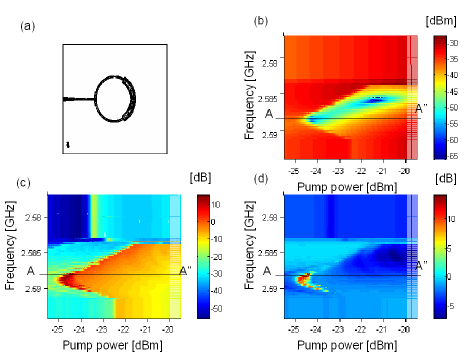
The intermodulation measurements presented in this paper were performed on two nonlinear NbN superconducting stripline microwave resonators. The layouts of these resonators, which we will refer to them by the names B1 () and B2 () for simplicity, are depicted in Fig. 2 (a), and in the inset of Fig. 5 respectively. The NbN resonator films were dc-magnetron sputtered on X X sapphire substrates near room temperature. The thickness of B1 and B2 resonators are and respectively. The films were patterned using standard photolithography process and etched by Ar ion-milling. The coupling gap between B1 and B2 resonators and their feedline was set to and respectively. The fabrication process parameters as well as other design considerations can be found elsewhere nonlinear features BB .
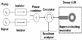
The basic intermodulation experimental setup that has been used, is schematically depicted in Fig. 1. The input field of the resonator is composed of two sinusoidal fields generated by external microwave synthesizers and combined using power combiner. The isolators in the signal paths were added to minimize crosstalk noise between the signals and suppress reflections. The signals used have unequal amplitudes, one, which we will refer to as the pump, is an intense sinusoidal field with frequency whereas the other, which we will refer to as the signal, is a small amplitude sinusoidal field with frequency where represents the frequency offset between the two signals. Due to the nonlinearity of the resonator, frequency mixing between the pump and the signal yields an output idler field at frequency Thus the output field from the resonator, which is redirected by a circulator and measured by a spectrum analyzer, consists mainly of three spectral components, the reflected pump, the reflected signal and the generated idler. The intermodulation amplification in the signal and idler is obtained, as it is shown in this paper, by driving the resonator to its onset of instability, via tuning the pump power.
In the intermodulation measurements, we limit the signal power to be several orders of magnitude smaller than the pump power as was assumed in Yurke , and require that all of the tones (pump, signal, idler) lie within the resonance band of the resonator during the intermodulation operation.
In Fig. 2 we present an intermodulation measurement applied to the first resonance mode of B1 resonator ( ), at where we measured the idler and the reflected signals (pump and signal) as a function of both the transmitted pump power and frequency. The experimental results presented here were obtained while decreasing the pump power gradually at each given frequency. The pump power range was set to include the onset of nonlinear bifurcations of B1 first mode which occurs at relatively low input powers of the order of dBm, whereas the signal was set to a constant power level of dBm, several orders of magnitude lower than the pump. The pump-signal frequency offset was set to very much narrower than the resonance band, (thus ensuring that all three signals lie within the resonance lineshape during the measurement process).
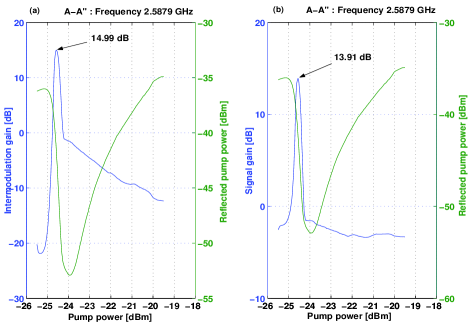
The reason for varying the pump power rather than its frequency to the edge of bifurcation, is mostly because the bifurcations along the frequency axis are abrupt nonlinear features BB in contrast to the bifurcations along the power axis which are more gradual. In Fig. 2, plots (b), (c) and (d) show the reflected pump power, idler gain and signal gain respectively, as colormaps of pump power and pump frequency. Large amplifications of the idler and the signal are measured simultaneously as the reflected pump power bifurcates, at a given pump frequency, as its power is decreased below some power threshold. These amplification peaks can be better seen in Fig. 3, where plots (a) and (b) show the A-A” cross-sections of the idler gain and the signal gain meshes respectively, plotted on the same axis with the reflected pump power at for comparison.
The amplification gain [dB], which is defined as the difference between the idler or signal power at the resonator output [dBm] and the signal power [dBm] at the resonator input (losses in cables and passive devices are calibrated), reaches dB at its peak in the case of the idler gain, and dB in the case of the signal gain.
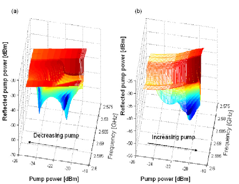
In Fig. 4 we show an unexpected power-frequency hysteresis of the reflected pump signal, which implies that the nonlinear resonance shape of the resonator, as a two dimensional function of input power and frequency, is multi valued, therefore a care must be taken in choosing the path in reaching each point in the power-frequency plane. Furthermore in the forward sweep of the pump no positive gain has been detected in the idler or signal, this may be partly due to the less steep slopes associated with bifurcations in the forward direction as seen in Fig. 4 (b).
Based on these high gains demonstrated experimentally at (and it is interesting to consider the feasibility of demonstrating some important quantum phenomena using these nonlinear effects in the quantum regime where ( m). As in Ref. Yurke , consider the mode of operation where a homodyne detection scheme with a local oscillator having the frequency of the pump is employed to measure the resonator output. The noise floor of the device is characterized by the power spectrum of the homodyne detector output, where the only externally applied input is the pump. In the nonlinear regime of operation noise squeezing occurs, namely, becomes dependent periodically on the phase of the local oscillator relative to the phase of the pump. In particular, for an intermodulation amplifier having a gain larger than unity, as the ones described in the present work, the maximum value of may become larger than the value corresponding to equilibrium noise. In the quantum limit, where , this effect is somewhat similar to the well known dynamical Casimir effect Dodonov , where a parametric excitation is employed to amplify vacuum fluctuations and to create real photons.
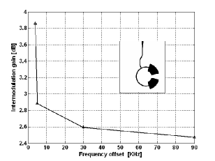
According to the idler/signal gain analysis carried out for the case of Duffing oscillator in Ref. Yurke , the idler/signal gain is expected to diverge as the oscillator is driven to its critical point in the limit . In order to examine whether similar gain-frequency offset relation holds in our nonlinear resonators, we employed the second resonance mode of B2 resonator depicted in the inset of Fig. 5, (which showed similar behavior under intermodulation operation as B1 resonator, though with lower gain levels). We varied the frequency offset applied between the two signals and recorded the maximum idler gain measured at that offset. The results in Fig. 5, show clearly that the maximum idler gain tends to increase as the frequency offset decreases, though the change was generally moderate compared with the dependence predicted in Yurke .
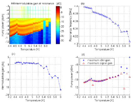
Moreover we studied the dependence of intermodulation gain on temperature using B2 resonator and its second mode. We increased the ambient temperature in small steps between and (below ). At each given temperature we set the pump frequency to the resonance frequency of the resonator corresponding to that temperature, and measured the idler and signal gains while gradually decreasing the pump power. The frequency offset between the pump and signal was set to , whereas the signal power was set to dBm. Fig. 6 summarizes the main results of this measurement. In plot (a) the idler gain mesh is shown as a function of temperature and pump power. The idler maximum gain is generally obtained (earlier) at higher pump powers as the temperature increases. In plot (b) the resonance frequency of the resonator is depicted as a function of temperature. The resonance frequency shifts towards lower frequencies as the temperature increases, due to increase in the nonlinear inductance and the penetration depth of the resonator as the temperature is increased nb ; hairpin temp . In plot (c) the maximum measured idler gain is plotted as a function of temperature. A plateau in the maximum idler gain is observed for low temperatures, but it decreases considerably as the temperature exceeds . Such plateau in measured intermodulation powers at low and intermediate temperatures have been reported in hairpin temp ; Koren , nevertheless whereas in hairpin temp ; Koren ; im theory the intermodulation power increases due to decrease in the intermodulation critical current density or increase in the kinetic inductance as the temperature is increased, our results show a decrease in the measured intermodulation gain as a function of temperature. This discrepancy can be attributed to the observed degradation of the device response (slope), responsible for the amplification, due to increase in the film surface resistance as the temperature is increased. In plot (d) the coordinations of the maximum measured idler and signal gains in the temperature-pump power plane are shown. The blue stars represent maximum idler gain coordination whereas the red triangles represent maximum signal gain coordination. The plot exhibit an excellent correlation between the two coordinations up to about
In conclusion, we have measured intermodulation gain in two of our nonlinear NbN superconducting stripline resonators, at relatively low temperatures An intermodulation gain as high as dB, was successfully achieved in one of the resonators, while applying frequency offset and dBm signal power. Moreover we showed that the reflected pump power, the signal gain and the idler gain demonstrate strong hysteretic behavior in the frequency-pump power plane. In addition, we briefly discussed the dependence of the intermodulation gain on ambient temperature, and frequency offset applied between the pump and signal. The intermodulation gain results were found to be both reproducible and controllable, which is a preliminary condition for any practical application. Whereas the underlying physics remains an outstanding challenge for future research, these nonlinear resonators operated as intermodulation amplifiers may be potentially employed, in the future, in generating low noise microwave signals, signal switching, and even in, producing quantum squeezed states Yurke and amplifying quantum zero point fluctuations.
E.B. would especially like to thank Michael L. Roukes for supporting the early stage of this research and for many helpful conversations and invaluable suggestions. Very helpful conversations with Bernard Yurke are also gratefully acknowledged. This work was supported by the German Israel Foundation under grant 1-2038.1114.07, the Israel Science Foundation under grant 1380021, the Deborah Foundation and Poznanski Foundation.
References
- [1] B. Abdo, E. Segev, Oleg Shtempluck, and E. Buks, cond-mat/0501114.
- [2] B. Abdo, E. Segev, O. Shtempluck, and E. Buks, cond-mat/0504582.
- [3] B. Abdo, E. Segev, O. Shtempluck, and E. Buks, cond-mat/0501236.
- [4] C. C. Chen, D. E. Oates, G. Dresselhaus and M. S. Dresselhaus, Phys. Rev. B. 45, 4788 (1992).
- [5] T. Dahm and D. J. Scalapino, J. Appl. Phys. 81, 2002 (1997).
- [6] D. E. Oates, S.-H. Park and G. Koren, Phys. Rev. Letts. 93, 197001 (2004).
- [7] B. A. Willemsen, K. E. Kihlstrom, and T. Dahm, Appl. Phys. Letts. 74, 753 (1999).
- [8] R. B. Hammond, E. R. Soares, B. A. Willemsen, T. Dahm, D. J. Scalapino, and J. R. Schrieffer, J. Appl. Phys. 84, 5662 (1998).
- [9] S. Cho and C. Lee, IEEE Trans. Appl. Supercond. 9, 3998 (1999).
- [10] H. Hoshizaki, N. Sakakibara, and Y. Ueno, J. Appl. Phys. 86, 5788 (1999).
- [11] D. E. Oates, S.-H. Park, M. A. Hein, P. J. Hirst, and R. G. Humphreys, IEEE Trans. Appl. Supercond. 13, 311 (2003).
- [12] R. Monaco, A. Andreone, and F. Palomba, J. Appl. Phys. 88, 2898 (2000).
- [13] B. Yurke and E. Buks, quant-ph/0505018.
- [14] I. Siddiqi, R. Vijay, F. Pierre, C. M. Wilson, L. Frunzio, M. Metcalfe, C. Riggetti, R. J. Schoelkopf, M. H. Devoret, D. Vion and D. Esteve, Phys. Rev. Letts., 94, 027005 (2005).
- [15] I. Siddiqi, R. Vijay, F. Pierre, C. M. Wilson, M. Metcalfe, C. Riggetti, L. Frunzio, and M. H. Devoret, Phys. Rev. Letts. 93, 207002 (2004).
- [16] VV. Dodonov, Adv. Chem. Phys. 119, 309 (2001).
- [17] B. A. Willemsen, K. E. Kihlstrom, T. Dahm, D. J. Scalapino, B. Gowe, D. A. Bonn, and W. N. Hardy, Phys. Rev. B. 58, 6650 (1998).