Spin-orientation-dependent spatial structure of a magnetic acceptor state in a zincblende semiconductor
Abstract
The spin orientation of a magnetic dopant in a zincblende semiconductor strongly influences the spatial structure of an acceptor state bound to the dopant. The acceptor state has a roughly oblate shape with the short axis aligned with the dopant’s core spin. For a Mn dopant in GaAs the local density of states at a site Å away from the dopant can change by as much by % when the Mn spin orientation changes. These changes in the local density of states could be probed by scanning tunneling microscopy to infer the magnetic dopant’s spin orientation.
pacs:
75.30.Gw, 71.70.Ej, 75.30.Hx, 75.50.PpSemiconductors doped with magnetic atoms have attracted much interest in recent years because of their potential applications in spintronic and quantum information technology.Wolf et al. (2001); Awschalom et al. (2002) The magnetic dopants introduce, in addition to magnetic moments, spin-polarized acceptor states into the semiconductor host.Vogl and Baranowski (1985); Zunger (1986); Schneider et al. (1987); Linnarsson et al. (1997); Mahadevan and Zunger (2004) Recent advances in scanning tunneling microscopy (STM) on GaAs have led to a better understanding of the anisotropic shape of these acceptor states.Yakunin et al. (2004a, b); Kitchen et al. (2005); Yakunin et al. (2005) The principal determinant of the anisotropic shape is the cubic symmetry of the lattice, and not the spin-orbit interaction, as the characteristic anisotropic shape is predicted to form even in semiconductors with negligible spin-orbit interaction.Yakunin et al. (2004b) However, the spin-orbit interaction does partly correlate the degree of acceptor state anisotropy with the spin orientation of the magnetic dopant.Tang and Flatté (2004) This correlation suggests the possibility of detecting the spin orientation of a magnetic dopant with a purely nonmagnetic probe. A similar phenomenon has been found in metallic magnetic systems. The spin-orbit interaction in iron films mixes the bands to yield a few percent difference in the LDOS for nanoscale magnetic domains (out-of-plane magnetization) and domain walls (in-plane magnetization).Bode et al. (2002) A coupling between spin and orbital degrees of freedom in quantum dots has been predicted to generate a spin-dependent electric field, although the size of that effect has been estimated to be very small.Levitov2003 A spin-orientation-dependent LDOS has yet to be observed in semiconductor systems.
Here we describe calculations of the dependence of the LDOS near a Mn dopant in GaAs on the Mn spin orientation. The orientation-dependence of the LDOS ranges from very high (%) for tunneling into the acceptor state, to quite small (%) for tunneling into continuum valence states far from the band edge. Tunneling into the continuum valence states resembles the qualitative behavior seen in iron films;Bode et al. (2002) the LDOS orientation-dependence is largest near critical points of the electronic structure: near the valence band edge for GaAs:Mn, and near an avoided level crossing for iron. Tunneling into discrete states such as the acceptor level, however, can be highly selective of spin and orbital character, as localized states with different orbital characters have narrow enough linewidths not to be spectrally distinguishable. Electron spin resonance (ESR) of the Mn spins has been observedSchneider et al. (1987) in GaMnAs; thus we predict that the ESR of a single Mn spin could be detected using a nonmagnetic scanning tunneling microscope.
The results presented in this paper are calculated from a tight-binding model, including on-site spin-orbit coupling, for an isolated Mn acceptor state in GaAs.Tang and Flatté (2004) The Mn spin is assumed to be a classical spin aligned in a certain direction, for example by applying an external magnetic field. The Mn spin degree-of-freedom is treated as an effective spin-dependent potential acting on the valence electrons of GaAs. Motivated by a - hybridization model,Vogl and Baranowski (1985) our Mn potential has spin-dependent matrix elements at the four nearest-neighbor sites. The Hamiltonian with a single Mn dopant takes the form
| (1) |
where is the tight-binding Hamiltonian for bulk GaAs with only nearest-neighbor hopping,Chadi (1977) and is the effective potential due to the Mn dopant with its spin pointing in the direction . When the Mn spin is aligned with the crystal axis, the potential is
| (2) |
where and are the spatial part (including both lattice sites and atomic orbitals) of the nonmagnetic and magnetic potential, and ’s are Pauli spin matrices. In our model, is non-zero at the Mn and the four nearest-neighbor As sites, and is only non-zero at the four nearest-neighbor As sites. The non-zero potential matrix elements at the neighboring As sites come from the hybridization among the Mn orbitals and the hybrids of GaAs. The potential for the Mn spin pointing in a general direction can then be obtained through a rotation in the spin space,
| (3) |
where
| (4) |
is the angle between the vector and the axis, and is a unit vector pointing to the direction of . We find that adding the Coulomb potential out to the 5th nearest neighbor to the impurity (and correspondingly reducing to keep the acceptor binding energy fixed) does not significantly alter the anisotropy of the acceptor state we describe in this paper and that is visible in Figs. 1-4.
Within this model, the energy spectrum of the system is independent of the Mn spin orientation. This is a direct consequence of the ability to transform two Hamiltonians with different Mn spin orientations into each other with a unitary transformation, which we now derive. The basis states ( and orbitals) are irreducible representations of the group and of the rotation group SO(3). As a result, the Mn potential is invariant under a rotation in real space,
| (5) |
where . The unitary transformations and correspond to the rotations of the lattice and of the atomic orbitals respectively. Note that the homogeneous Hamiltonian including the spin-orbit interaction is invariant under a full rotation,
| (6) |
where
| (7) |
With Eqs. (3) and (5), the rotation of the Mn spin can be achieved via rotating the whole lattice in the opposite direction,
| (8) |
if .

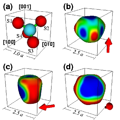
Although the energy spectrum (and thus the DOS) of the magnetic dopant in a zincblende or diamond symmetry semiconductor is independent of dopant spin orientation, the LDOS can vary considerably. The symmetry of the LDOS would be tetrahedral () if there were no spin-orbit interaction and also no Jahn-Teller distortion. For a Mn dopant substituting for a Ga atom no Jahn-Teller distortion is seen.Schneider et al. (1987) The actual symmetry of the LDOS for GaAs:Mn, however, is lowered by the spin-orbit interaction, and the resulting symmetry depends on the Mn spin orientation as shown in Fig. 1. The LDOS is calculated as the imaginary part of the Green’s function, LODS.
To understand how the spatial symmetry and spin orientation are correlated we consider the angular momentum character of the acceptor states. The acceptor states found in our model are spin-polarized antiparallel to the Mn core spin due to the exchange coupling between the GaAs valence states and Mn states.Vogl and Baranowski (1985) Only one acceptor state can be occupied by a hole, as the Coulomb interaction prevents two holes from binding to the Mn dopant. The degeneracy of the singly occupied acceptor states with different orbital angular momentum is lifted by the spin-orbit interaction, and the lowest energy configuration has an orbital angular momentum aligned antiparallel to the Mn core spin, leading to a composite spin associated with the Mn dopant. As an state of an atom centered at has a nodal line along , the probability density of the acceptor state should be small along the line extending from the dopant parallel to the core spin direction. Thus a contour surface of the LDOS at the lowest acceptor level (shown in Fig. 1) has an approximately oblate shape with the short axis aligned with the Mn core spin. The shape of the level does not depend on which way the Mn core spin is pointing along the axis — only on the orientation of the axis itself. One consequence of this shape is anisotropic spin-spin interaction,van Schilfgaarde and Mryasov (2001); Zaránd and Jankó (2002); Brey and Gómez-Santos (2003); Fiete et al. (2003, 2005); Tang and Flatté (2004); Mahadevan et al. (2004); Timm and MacDonald (2005) in which the overlap is larger when the two Mn spins are perpendicular to the axis that joins them. Figure 1 shows three examples for which the Mn spin is oriented along one of the high symmetry axes of a cubic crystal. When the Mn spin is aligned with the (b) , (c) or (d) axis, the symmetry of the state is lowered from to (b) , (c) and (d) . Although the spin direction is indicated with an arrow, the panels in Fig. 1 would look the same if the spin direction is reversed, so for example the acceptor state would appear as Fig. 1(b) for the Mn spin pointing in the or direction.
Figure 2 shows the energy spectrum near the valence band edge and the LDOS spectra at the four nearest-neighbor As sites S1–S4. These sites are indicated by their labels in Fig. 1(a). For a Mn at the origin, S1 is at , S2 at , S3 at and S4 at , where is the lattice constant. As pointed out above, for all orientations of the Mn spin the energies of the peaks in the spectra are the same. The Mn dopant itself sits at a high symmetry location, and thus the LDOS at the Mn site is independent of the spin orientation. The spectral weight of the acceptor state at the four nearest-neighbor As sites evolves as the Mn spin rotates. Results are shown in Fig. 2(c) for S1 (solid line), S2 (dashed line), S3 (dot-dashed line) and S4 (double-dot-dashed line). From to the spectra at S3 (S4) is the same as S2 (S1). From to the spectra at S2 is the same as S1. The orbital angular momentum aligns with the Mn spin, and thus the spectral weight tends to increase when the site is away from the spatial line drawn through the Mn dopant and parallel to the Mn spin. Conversely the spectral weight tends to decrease when the site is close to this spatial line. The variation among the nearest-neighbor As sites is greater than a factor of two. For sites farther from the Mn dopant, the dependence of the LDOS on Mn spin orientation can be much greater. The variability of the LDOS of the continuum valence band states is considerably less; the LDOS for all three spin orientations shown in Fig. 2 at the valence maximum varies by , but is the same within a percent below the split-off energy ( meV).
To show the LDOS variability for different Mn spin orientations as a function of distance, we plot in Fig. 3 the probability density of the Mn acceptor state at the Ga sites along the direction, which is usually the surface normal of a cleaved GaAs sample. The background LDOS has been subtracted off so that the behavior at large distances is visible, and the probability density has been normalized to unity at the Mn site. The background LDOS for the meV energy linewidth is about eV-1. A clear feature of Fig. 3 is that the probability density drops significantly when the Mn spin is oriented parallel to rather than perpendicular to . Once the distance is larger than about 4 atomic layers ( Å from the Mn site), the probability density changes by roughly an order of magnitude as the Mn spin orientation is changed from parallel to perpendicular to . At large distances from the Mn site we expect the wave function follows a simple exponential tail with a decay length we estimate based on the effective masses of the heavy and light holes and on the acceptor level energy. In our tight-binding model, the effective masses along for heavy and light holes are about and . For the acceptor level, the binding energy meV and the decay length Å, where the averaged effective mass is . The visible LDOS variability will be significantly reduced at distant sites due to the presence of a background LDOS from the valence band tail.
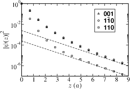
Figure 4 shows the field of view at the plane four atomic layers from the Mn layer. This is the image most relevant to detecting the ESR of a single Mn dopant in GaAs. The procedure would be to cleave the GaAs along the plane, and locate an isolated Mn a few layers down from the surface (here we have chosen four layers, but as shown in Fig. 3 any layer would do except the surface layer). At the central Ga site on the surface plane, here located Å from the Mn site in the material below, there is approximately a % change in LDOS when the Mn spin switches from parallel to the surface normal to perpendicular to the surface normal. The LDOS also differs for the two Mn orientations perpendicular to the surface normal, although that difference is considerably less (%). The overall shape of the anisotropic acceptor state is very similar for all three spin orientations chosen for Fig. 4(a-c), as the gross shape is governed by the cubic symmetry of the crystal,Yakunin et al. (2004b) but the degree of anisotropy (appearing as the magnitude of the state’s LDOS along this spatial slice) varies by up to %. These characteristics suggest that atomic-scale resolution is not necessary to distinguish the Mn spin axis from measurements such as those suggested by Fig. 4.
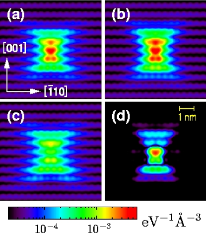
The differences in LDOS shown in Fig. 4 suggest that a repetitive preparation of the Mn dopant in a particular spin state (using ESR techniques) and measurement of the spin orientation at a time delay (using the nonmagnetic STM measurement) would be able to produce an oscillatory LDOS. The temporal frequency of the LDOS created by the Mn spin’s precession would be determined by the magnetic field strength and factor of the Mn dopant (measuredSchneider et al. (1987) to be ), and the spatial structure could be determined from Fig. 4. Based on the linewidth in bulk ESR measurements done at GHzSchneider et al. (1987) ( Tesla), the spin coherence time of a single Mn spin is estimated to be longer than ns. Ultrafast STM detection at GHz has been achieved.Steeves1998 If the static magnetic field of an ESR apparatus were directed parallel to , then precession would involve an oscillation between Fig. 4(b) and Fig. 4(c). As the Mn spin has , pulses of oscillating magnetic fields could be used to manipulate the populations of the , , eigenstates. For the LDOS would appear as Fig. 4(a). The orbital wavefunctions transform according to in the tetrahedral crystal, so the spatial structure of can be written as . Thus the spatial structure of the state would be Fig. 4(a) subtracted from the sum of Fig. 4(b) and Fig. 4(c). The difference between this state and the states is shown in Fig. 4(d).
We have shown how the anisotropic spatial shape of the Mn acceptor state, which principally originates from the cubic symmetry of the GaAs lattice, is influenced by spin-orbit interaction. Calculations of the Mn acceptor state were performed within a tight-binding model including spin-orbit interaction and - hybridization. The acceptor state has an approximately oblate shape with the short axis aligned with the Mn core spin. The difference in the LDOS for Mn spins oriented in two different directions at a site located Å away from the Mn dopant can be as high as %. We suggest that the high visibility of the spin orientation in the LDOS for Mn spins can be probed by scanning tunneling microscopy, and this can lead to a nonmagnetic detection scheme for single-spin ESR.
We acknowledge conversations with P. M. Koenraad, J. Levy, A. Yu. Silov, and A. M. Yakunin. This work was supported by the USARO under MURI Grant No. DAAD19-01-1-0541.
References
- Wolf et al. (2001) S. A. Wolf, D. D. Awschalom, R. A. Buhrman, J. M. Daughton, S. von Molnár, M. L. Roukes, A. Y. Chtchelkanova, and D. M. Treger, Science 294, 1488 (2001).
- Awschalom et al. (2002) D. D. Awschalom, N. Samarth, and D. Loss, eds., Semiconductor Spintronics and Quantum Computation (Springer Verlag, Heidelberg, 2002).
- Vogl and Baranowski (1985) P. Vogl and J. M. Baranowski, Acta. Phys. Polo. A67, 133 (1985).
- Zunger (1986) A. Zunger, Solid State Physics 39, 275 (1986).
- Schneider et al. (1987) J. Schneider, U. Kaufmann, W. Wilkening, M. Baeumler, and F. Köhl, Phys. Rev. Lett. 59, 240 (1987).
- Linnarsson et al. (1997) M. Linnarsson, E. Janzén, B. Monemar, M. Kleverman, and A. Thilderkvist, Phys. Rev. B 55, 6938 (1997).
- Mahadevan and Zunger (2004) P. Mahadevan and A. Zunger, Phys. Rev. B 69, 115211 (2004).
- Yakunin et al. (2004a) A. M. Yakunin, A. Y. Silov, P. M. Koenraad, W. Van Roy, J. De Boeck, and J. H. Wolter, Physica E 21, 947 (2004a).
- Yakunin et al. (2004b) A. M. Yakunin, A. Y. Silov, P. M. Koenraad, J. H. Wolter, W. Van Roy, J. De Boeck, J.-M. Tang, and M. E. Flatté, Phys. Rev. Lett. 92, 216806 (2004b).
- Kitchen et al. (2005) D. Kitchen, A. Richardella, and A. Yazdani, J. of Superconductivity 18, 23 (2005).
- Yakunin et al. (2005) A. M. Yakunin, A. Y. Silov, P. M. Koenraad, J.-M. Tang, M. E. Flatté, W. Van Roy, J. De Boeck, and J. H. Wolter, cond-mat/ 0505536 (2005).
- Tang and Flatté (2004) J.-M. Tang and M. E. Flatté, Phys. Rev. Lett. 92, 047201 (2004).
- Bode et al. (2002) M. Bode, S. Heinze, A. Kubetzka, O.Pietzsch, X. Nie, G. Bihlmayer, S. Blügel, and R. Wiesendanger, Phys. Rev. Lett. 89, 237205 (2002).
- (14) L. S. Levitov and E. I. Rashba, Phys. Rev. B67, 115324 (2003).
- Chadi (1977) D. J. Chadi, Phys. Rev. B 16, 790 (1977).
- van Schilfgaarde and Mryasov (2001) M. van Schilfgaarde and O. N. Mryasov, Phys. Rev. B 63, 233205 (2001).
- Zaránd and Jankó (2002) G. Zaránd and B. Jankó, Phys. Rev. Lett. 89, 047201 (2002).
- Brey and Gómez-Santos (2003) L. Brey and G. Gómez-Santos, Phys. Rev. B 68, 115206 (2003).
- Fiete et al. (2003) G. A. Fiete, G. Zaránd, and K. Damle, Phys. Rev. Lett. 91, 097202 (2003).
- Fiete et al. (2005) G. A. Fiete, G. Zaránd, B. Jankó, P. Redliński, and C. P. Moca, Phys. Rev. B 71, 115202 (2005).
- Mahadevan et al. (2004) P. Mahadevan, A. Zunger, and D. D. Sarma, Phys. Rev. Lett. 93, 177201 (2004).
- Timm and MacDonald (2005) C. Timm and A. H. MacDonald, Phys. Rev. B 71, 155206 (2005).
- (23) G. M. Steeves, A. Y. Elezzabi and M. R. Freeman, Appl. Phys. Lett. 72, 504 (1998).