Measurement of Dissipation of a Three-Level rf SQUID Qubit
Abstract
The dissipation-induced relaxation () time of a macroscopic quantum system - a -type three-level rf SQUID flux qubit weakly coupled to control and readout circuitry (CRC) - is investigated via time-domain measurement. The measured interwell relaxation time of the qubit’s first excited state, s, corresponds to an effective damping resistance of the flux qubit M which is much lower than the intrinsic quasiparticle resistance of the Josephson tunnel junction. An analysis of the system shows that although the CRC is very weakly coupled to the qubit it is the primary source of damping. This type of damping can be significantly reduced by the use of more sophisticated circuit design to allow coherent manipulation of qubit states.
pacs:
85.25.Dq, 85.25.Cp, 03.65.Yz, 03.67.PpThe superconducting flux qubit, being immune to charge fluctuation, has attracted much attention in the area of solid-state quantum computation. The flux qubit, consisting of a superconducting loop interrupted by either one (rf SQUID) J-R-Friedman-2000 or three Josephson junctions (persistent current qubit or simply PC qubit) TP-Orlando-1999 , usually is a double well potential when a magnetic flux close to one half of a flux quantum is applied. The lowest states of each well serve as the two qubit states corresponding to macroscopic currents circulating around the loop with clockwise and anti-clockwise directions respectively and thus can be discriminated by a dc SQUID magnetometer. Quantum superposition of distinct macroscopic states, a prerequisite for quantum computation, was observed in both types of flux qubits at about the same time a couple of years ago J-R-Friedman-2000 ; MQC-14 . Since then rapid development in PC qubit has led to the demonstration of coherent manipulations of a single qubit I-Chiorescu-science , entanglement between a PC qubit and its readout magnetometer I-Chiorescu-nature and between two PC qubits Mooij-PRL-2005 . Furthermore, the relaxation time () and dephasing time () of the PC qubit have been measured directly using time-domain techniques providing invaluable information about mechanisms of and solutions to decoherence I-Chiorescu-science ; I-Chiorescu-nature ; Mooij-PRL-2005 ; y-yu-prl2004 . In contrast, despite intense efforts similar measurement have not been possible in the rf SQUID qubit due to shorter decoherence times in the particular systems measured. It is essential to study the sources of this decoherence to understand if it is fundamental to this type of qubit or can be overcome by more sophisticated design. One very important element of this is the dissipation due to the coupling of the qubit to the environment. To the best of our knowledge the dissipation rate of the rf SQUID qubit was inferred previously from escape probability distribution measurements which can provide only an order of magnitude estimate of the damping resistance Cosmelli-1 ; cosmelli-reply ; silvestrini-prb-2004 . Furthermore, the results have led to more questions than answers because of the lack of an accurate knowledge about crucial sample parameters and the use of an effective temperature that is more than ten times of the bath temperature to extract from the data Han-Rouse-comment ; cosmelli-reply . Therefore, a more direct and quantitative measurement of dissipation in rf SQUID qubits is needed in order to clarify the origin and the limit of the decoherence in the system. In this Letter, we report results of a relaxation time measurement of an rf SQUID qubit using time-resolved techniques. In our experiment all parameters that enter the qubit’s Hamiltonian are obtained from independent measurements which enables us to determine the damping resistance of the qubit with significantly improved accuracy. The result indicates that although the inductive coupling between the qubit and its control and readout circuits (CRC) is rather weak by conventional standards, it nevertheless is the dominant source of dissipation inducing relaxation from excited states. Hence, great care must be taken in the design of rf SQUID qubits and associated CRC to limit dissipation to levels allowing coherent manipulation of qubit states Y-Makhlin-RMP .
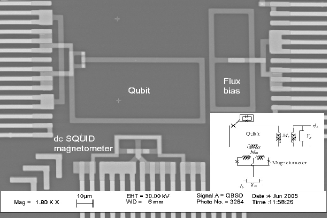
The qubit used in our experiment is a variable barrier rf SQUID in which the single Josephson junction in an ordinary rf SQUID is replaced by a low inductance dc SQUID as shown in Fig. 1(a). The two-dimensional (2D) potential energy surface of such a variable barrier rf SQUID is SQUID-4
| (1) |
Here, is the flux quantum; is the ratio of the inductances of the rf SQUID and dc SQUID; , , and are the flux applied to and the net flux enclosed in the rf SQUID (dc SQUID) in units of . A plot of the qubit’s first four energy levels is shown in Fig. 2(a). Notice that sets the energy bias between the two wells while determines the tunnel splitting Thus the energy level structure of the qubit (e.g., and ) can be varied in situ by adjusting and . The qubit is inductively coupled to a hysteretic dc SQUID magnetometer and the state of the qubit can be determined by measuring the flux-dependent switching current of the magnetometer I-Chiorescu-science .
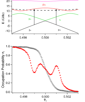
In our experiment the rf SQUID is configured as a -type three-level qubit with each potential well having only one level as the and logic states and an auxiliary level just above the potential barrier as shown in Fig. 2(a). Compared to a flux qubit in the usual two-level configuration the -type three-level qubit has significantly faster gates and much lower intrinsic error rate Z-Zhou-PRB2002 . Moreover, since gate operations in such a three-level qubit are via the auxiliary level, it does not involve the tunnel splitting energy which depends exponentially on the potential barrier MHS-Amin-PRB . For these reasons the three-level flux qubit puts relatively less-strict constraints on sample fabrication. For , the two lowest levels of the qubit are localized, corresponding to currents circulating in opposite directions in the qubit loop. For convenience, we denote the state localized in the left (right) well by (). The energy difference between the and states can be varied continuously by sweeping the external flux . Microwave radiation with frequency matching the energy difference between the short-lived auxiliary state and ground state (e.g., for ) induces transitions between them. In general, the qubit can relax to the ground state from the auxiliary state via two pathways: and , assuming . The probability of finding the qubit in the first excited state depends on various transition rates (including both stimulated absorption/emission and spontaneous emission) between the three states involved. The lifetime of first excited state, , is proportional to damping resistance, Re, where is the admittance seen by the qubit and is the transition frequency of the relevant radiative decay process AI-Larkin-JETP1986 ; DSP-2 . Therefore, dissipation in an rf SQUID qubit can be investigated quantitatively via direct measurement of between qubit states.
The sample was fabricated using a self-aligned Nb trilayer process SBU-trilayer . The size of the rf SQUID loop is m In order to extract the qubit damping resistance from the measured time one must have an accurate knowledge of key SQUID parameters, such as total junction capacitance , loop inductance , and and . In our experiment, the loop inductance pH and are estimated using a 3D inductance calculation program, and were determined from the maximum size of the measured hysteretic loop (taking into account the effect of macroscopic quantum tunneling) and at , respectively MQT-3 ; SQUID-6 . The total capacitance of the junctions in the rf SQUID, fF, is obtained from microwave spectroscopy which agrees very well with the value determined from the total size of the junctions ( m2) and the specific capacitance of the Nb/AlO/Nb trilayer ( fF/m2). In addition, the critical current density inferred from , , and the junction size, A/cm2, agrees very well with that measured directly from co-fabricated large junctions. The mutual inductances between the magnetometer and the qubit is pH and that between qubit and flux bias line is pH, respectively. The sample is mounted in a oxygen-free copper cell thermally anchored to the mixing chamber of a dilution refrigerator. A superconducting shield at K, a cryoperm shield at K, and a -metal shield at room temperature are used to reduce flux bias fluctuations from the ambient magnetic field. All leads to the sample cell are filtered with electromagnetic interference filters at room temperature, low-pass RC filters at K, and microwave filters at mixing chamber temperature. A cryogenic coaxial microwave cable, with dB and dB attenuators thermally anchored to the K plate and mixing chamber respectively, couples microwaves to the sample. Battery-powered low-noise preamplifiers are used to monitor the bias current and voltage of the magnetometer. All ac-powered instruments are optically isolated from the battery-powered circuits. Diagnostic tests using low critical current junctions ( A) indicate that extrinsic noise is negligible at mK.
We first measure the excitation probability, , of the state vs. flux bias at constant microwave frequency and different to determine the energy level structure of the qubit J-R-Friedman-2000 . By setting the amplitude and duration of bias current pulse properly the magnetometer either switches to finite voltage or stays at zero voltage depending on the qubit state being or . The result of the spectroscopy measurement is also used to select the values of and for time-resolved measurements. The result is shown in Fig. 2. For , when is swept from negative to positive there is a step-like transition from to indicating the change of ground state from to . When irradiated by continuous microwave (CW) a peak (dip) in appeared at , corresponding to microwave induced excitation from the ground state to the second excited state. The excitation are indicated by arrows in the energy level diagram of the qubit (Fig 2 inset), calculated using the independently determined sample parameters and the full 2D potential (1). When the value of is varied, while keeping constant, the position of microwave induced peaks shifted as expected from the calculated level diagram.
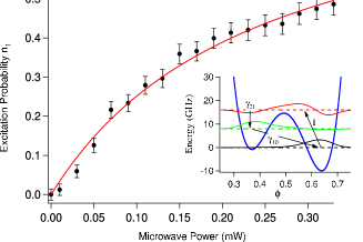
Next, we measure as a function of CW power at where GHz. Fig. 3 shows the peak height as a function of the microwave power measured at the top of the cryostat. Since the microwave used in our experiment is either CW or pulses with duration much longer than the decoherence time, the dynamics of the qubit is incoherent. Hence, the time evolution of the qubit state under microwave irradiation can be described by the following master equation
| (2a) |
| (2b) |
| (2c) |
where, , , and are the normalized populations of the ground state, the first excited state, and the second excited (the auxiliary) state, is the rate of stimulated transitions between the ground state and the auxiliary state, and is the spontaneous decay rate from to (). Note, in our experiment we have () for () while regardless the value of . For weak microwave fields one has according to Fermi’s golden rule, where is a coupling constant dependent of the microwave circuit used. Under irradiation of CW, the three-level qubit is in a steady state, , and Eq. (2) can be solved exactly to give
| (3) |
Fitting the measured vs. to Eq. (3) yields and mW. This value of corresponds to a ratio between the two relevant matrix elements which agrees very well with calculated using the independently determined qubit parameters.
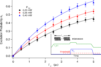
Although the steady state measurement provided useful information about the system one cannot extract from it alone. To obtain we used a time-domain technique. We start each measurement cycle by applying a microwave pulse of duration . A bias current pulse is then applied to the magnetometer to readout the state of qubit. The flux bias is kept constant at . The time evolution of is obtained by varying and repeating the cycle more than times for each value of . A few milliseconds of delay was inserted between successive cycles to allow the qubit to relax to the ground state before each new measurement cycle. Fig. 4 shows for three different microwave power levels. Since mW, we have . Under this condition, rapidly saturates to a constant , which depends on at and (2b) can be solved analytically, by replacing with , to give:
| (4) |
We verified the validity of the approximate solution (4) by solving Eq. (2) numerically. The result is in excellent agreement with (4) at . Since is known from the steady state measurement, fitting the measured to (4) gives s. In addition, the results of steady state and time dependent excitation measurements together yield ns and mWs-1 confirming the applicability of (4).
It is well known that the damping resistance’s contribution to time of an rf SQUID qubit is proportional to AI-Larkin-JETP1986
| (5) | |||||
where is the resistance quantum. From (5), using the value of calculated from the independently determined qubit parameters, we have M, which is more than times lower than the measured quasiparticle resistance of co-fabricated junctions Vijay-2005 . Hence, we conclude that the contribution of quasiparticles to qubit dissipation is negligible. On the other hand, weak but finite inductive coupling to the control and readout circuits result in a damping resistance Re, where and are the admittances of the magnetometer and the flux bias circuits seen by the qubit and is the transition frequency between the and states, respectively. For the CRC used in our experiment which is illustrated in Fig. 1(b)
| (6) | |||||
around , where is the difference of Josephson inductances of the two junctions in the magnetometer and is the sum of the geometric inductance ( pH) and the Josephson inductances of the magnetometer loop. Since the high frequency dampings (at of the flux bias and magnetometer’s bias/measurement circuits are essentially the same, we model them by a shunting impedance . Substituting the values of , and Josephson inductances of the two junction evaluated at working point of the magnetometer ( A, ) into (6) yields which agrees very well with derived from the measurement of escape rate of the magnetometer in phase-diffusion regime Mannik-2005 . The value of obtained is typical of the high frequency impedance of transmission lines indicating that the interwell relaxation of the qubit is mainly induced by its coupling to electromagnetic environment through the flux bias and readout circuits. In principle, changing the working point of the magnetometer and further reducing coupling between the qubit and CRC could result in longer coherence time. Unfortunately, it could not be done in our experiment since the magnetometer’s maximum critical current, A, is more than three times higher than the target and consequently the flux applied to the magnetometer () is bounded in a very tight range slightly below to achieve nearly single-shot readout. On the other hand, according to Eq. (6), contribution to the damping resistance from the integrated on-chip flux bias line is Re M. The use of off-chip flux bias, as those employed in the experiments observing coherent oscillations in the persistent current qubits I-Chiorescu-science ; I-Chiorescu-nature ; Mooij-PRL-2005 , would significantly increase Re but this approach would be very difficult to apply to a circuit containing many qubits required for practical quantum information processing. Currently, we are developing advanced designs for the qubit bias and readout circuits that are predicted to decrease their contributions to the qubit damping by several orders of magnitude. In addition, due to limitations in our microwave coupling circuit, this rf SQUID qubit was configured as a magnetometer which makes it susceptible to ambient field fluctuations. This source of decoherence can be greatly suppressed by using qubits with gradiometer geometries.
In summary, the dissipation of a Nb rf SQUID qubit, which is coupled inductively to the flux bias and readout circuits, is determined by measuring the interwell relaxation time between the ground state and first excited state with the -type three-level configuration. Time-domain measurement of the excitation probability of the first excited state yields s corresponding to a damping resistance M for the qubit Analysis of the system indicates that the dominant sources of qubit dissipation are the flux bias and magnetometer readout circuits. Since this kind of dissipation-induced qubit decoherence can be greatly suppressed with more sophisticated designs we believe it does not impose a fundamental limit to this type of qubit.
We thank K. K. Likharev for useful discussions. The work is supported in part by NSF (Grant No. DMR-0325551) and by AFOSR, NSA and ARDA through DURINT (Grant No. F49620-01-1-0439).
References
- (1) J. R. Friedman et al., Nature 406, 43 (2000).
- (2) T. P. Orlando et al., Phys. Rev. B 60, 15398 (1999).
- (3) C. H. van der Wal et al., Science 290, 773 (2000).
- (4) I. Chiorescu, Y. Nakamura, C. J. P. M. Harmans, and J. E. Mooij, Science 299, 1869 (2003).
- (5) I. Chiorescu et al., Nature 431, 159 (2004).
- (6) J. B. Majer et al., Phys. Rev. Lett. 94, 090501 (2005).
- (7) Y. Yu et al., Phys. Rev. Lett. 92, 117904 (2004).
- (8) C. Cosmelli et al., Phys. Rev. Lett. 82, 5357 (1999).
- (9) C. Cosmelli, Phys. Rev. Lett. 86, 4192 (2001).
- (10) V. Corato et al., Phys. Rev. B 70, 172502 (2004).
- (11) S. Han and R. Rouse, Phys. Rev. Lett. 86, 4191 (2001).
- (12) Y. Makhlin, G. Schön, and A. Shnirman, Rev. Mod. Phys. 73, 357 (2001).
- (13) S. Han, J. Lapointe, and J. Lukens, in Single-Electron Tunneling and Mesoscopic Devices, edited by H. Koch and Lübbig (Springer-Verlag, Berlin Heidelberg, 1992), Vol. 31, pp. 219–222.
- (14) Z. Zhou, S.-I. Chu, and S. Han, Phys. Rev. B 66, 054527 (2002).
- (15) M. H. S. Amin, A. Y. Smirnov, and A. M. van den Brink, Phys. Rev. B 67, 100508 (2003).
- (16) A. I. Larkin and Y. N. Ovchinnikov, Sov. Phys. JETP 64, 185 (1986).
- (17) D. Esteve, M. H. Devoret, and J. M. Martinis, Phys. Rev. B 34, 158 (1986).
- (18) W. Chen, V. Patel, and J. E. Lukens, Microelectronic Engineering 73, (2004).
- (19) D. B. Schwartz, B. Sen, C. N. Archie, and J. E. Lukens, Phys. Rev. Lett. 55, 1547 (1985).
- (20) S. Han, J. Lapointe, and J. E. Lukens, in Activated Barrier Crossing, 1st ed., edited by G. Fleming and P. Hänggi (World Scientific, Singapore, 1993), Chap. 9, pp. 241–267.
- (21) V. Patel, W. Chen, S. Pottorf, and J. E. Lukens, IEEE Trans. Appl. Supercon. (2005), in press.
- (22) J. Mannik et al., Phys. Rev. B 71, 220509(R) (2005).