URL: ]http://cua.mit.edu/ketterle_group/
Interference of Bose-Einstein Condensates on an Atom Chip
Abstract
We have used a microfabricated atom chip to split a single Bose-Einstein condensate of sodium atoms into two spatially separated condensates. Dynamical splitting was achieved by deforming the trap along the tightly confining direction into a purely magnetic double-well potential. We observed the matter wave interference pattern formed upon releasing the condensates from the microtraps. The intrinsic features of the quartic potential at the merge point, such as zero trap frequency and extremely high field-sensitivity, caused random variations of the relative phase between the two split condensates. Moreover, the perturbation from the abrupt change of the trapping potential during the splitting was observed to induce vortices.
pacs:
03.75.Dg, 03.75.Kk, 39.20.+qCoherent manipulation of matter waves is the ultimate goal of atom optics, and diverse atom optical elements have been developed such as mirrors, beamsplitters, gratings, and waveguides. An atom chip integrates these elements on a microfabricated device allowing precise and stable alignment Müller et al. (1999). Recently, this atom chip technology has been combined with Bose-Einstein condensed atoms Ott et al. (2001); Hänsel et al. (2001), and opened the prospect for chip-based atom interferometers with Bose-Einstein condensates. Despite various technical problems Leanhardt et al. (2002a); Fortágh et al. (2002); Leanhardt et al. (2003); Jones et al. (2003); Estève et al. (2004), there have been advances toward that goal, such as excitationless propagation in a waveguide Leanhardt et al. (2002a) and demonstration of a Michelson interferometer involving splitting along the axis of a single waveguide Wang et al. (2005).
Coherent splitting of matter waves into spatially separate atomic wave packets with a well-defined relative phase is a prerequisite for further applications such as atom interferometry and quantum information processing, and it has been a major experimental challenge. The methods envisioned for coherent splitting on atom chips can be divided in two classes. One is splitting in momentum space and subsequently generating a spatial separation, using scattering of atoms from a periodic optical potential Martin et al. (1988); Wang et al. (2005). The other is dynamical splitting by directly deforming a single wave packet into two spatially separated wave packets, which can be considered as cutting off the link between two wave packets, i.e., stopping tunneling through the barrier separating two wave packets. Splitting in momentum space has led to remarkably clean interferometric measurements when the atoms were allowed to propagate freely after splitting, but it has been pointed out that momentum splitting of confined atoms (e.g. inside a waveguide) is problematic due to spatially dependent phase shifts induced by atom-atom interactions during separation Wang et al. (2005); Olshanii and Dunjko (2005). Dynamical splitting in real space instead is perfectly compatible with keeping atoms confined, a feature beneficial to the versatility of interferometers. There has been a theoretical debate concerning the adiabatic condition for coherent dynamical splitting Javanainen and Wilkens (1997); Leggett and Sols (1998); Menotti et al. (2001); Pezzé et al. (2004). In our recent experiment with an optical double-well potential, we demonstrated that it is possible to dynamically split a condensate into two parts in a coherent way Shin et al. (2004a).
In this work, we studied the dynamical splitting of condensates in a purely magnetic double-well potential on an atom chip. We developed an atom chip to generate a symmetric double-well potential and succeeded in observing the matter wave interference of two split condensates, from which the coherence of the splitting process was investigated. We found that the mechanical perturbations during splitting are violent enough to generate vortices in condensates. We discuss the adiabatic condition of the splitting process.
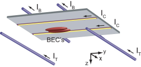
A magnetic double well potential was realized with an atom chip using a two-wire scheme Hinds et al. (2001). The experimental setup of the atom chip is shown in Fig. 1. When two chip wires have currents, , in the direction and the external magnetic field, , is applied in the direction, two lines of local minima in the magnetic field are generated above the chip surface. Each local minimum has a quadruple field configuration in the plane, and with an additional non-zero magnetic field in the axial direction (-direction), two Ioffe-Pritchard magnetic traps can be formed. The relative magnitude of to the field from determines the direction of separation and the distance of the two traps. The atom chip was set to face downward and the two traps are vertically (horizontally) separated when (). is the critical field magnitude for merging two magnetic harmonic potential to form a single quartic potential, where is the distance between the two chip wires and is the permeability of the vacuum. The merge point is located at the middle of the two wires and away from the chip surface. In our experiment, m; thus, the splitting happened more than 200 m away from the chip wires to avoid deleterious surface effects Leanhardt et al. (2002a); Fortágh et al. (2002); Leanhardt et al. (2003); Jones et al. (2003); Estève et al. (2004). The chip wires of 12 m height and 50 m width were electroplated with Au on a thermally oxidized Si substrate with a 2 m-thick Au evaporated film. The chip was glued on an Al block for heat dissipation Groth et al. (2004) and the current capacity was 5 A in a continuous mode.
The axial trapping potential was carefully designed to ensure that condensates split perpendicular to the axial direction and stay in the same axial position. The two wells have opposite responses to : positive makes the left (right) well move upward (downward). If changes along the axial direction, the two wells are no longer parallel and the gravitational force would cause an axial displacement of the two split condensates. When endcap wires are placed only on the chip surface as in our previous work Shin et al. (2004b), a non-zero field gradient inevitably accompanies a field curvature for the axial confinement, i.e., changes from positive to negative along the axial direction. In order to provide the axial confinement and at the same time minimize , we placed two pairs of external wires 1.5 mm above and 4 mm below the chip surface. This three-dimensional design of axial confinement was necessary for obtaining the interference signal of two split condensates. Moreover, maintaining the geometric symmetry of two wells will be crucial for longer coherence time after splitting Shin et al. (2004a).
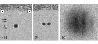
The splitting process was demonstrated with the experimental procedures described in Fig. 2. Bose-Einstein condensates of 23Na atoms were transferred and loaded in a magnetic trap generated by the atom chip Leanhardt et al. (2002a, b); Shin et al. (2004b). Experimental parameters were A, G, G, and the axial trap frequency Hz. Condensates were first loaded in the bottom well, 500 m away from the chip surface, brought up to 30 m below the merge point in 1 s, and held there for 2 s to damp out excitations. The long-living axial dipole excitation induced in the transfer phase was damped by applying a repulsive potential wall at the one end of the condensates with a blue-detuned laser beam (532 nm) 111In a perfectly symmetric double-well potential, two condensates would oscillate in phase after splitting. Furthermore, this could be used for developing a rotation-sensitive atom interferometer with a guiding potential. However, the axial trap frequencies for the two wells were found to be different by 12 due to the imperfect fabrication of wires.. The whole procedures was carried out with a radio-frequency (rf) shield and, just before splitting, condensates contained over atoms without a discernible thermal population. Splitting was done by ramping linearly from - mG to mG in 200 ms. The separation between two condensates was controlled by the final value of . The magnetic trap was then quickly turned off within 20 s, much shorter than the inverse of any trap frequency, preventing random perturbations. High-contrast matter wave interference fringes were observed after releasing the condensates and letting them expand in time-of-flight (Fig. 2), indicating that the splitting procedure was smooth enough to produce two condensates having uniform phases along their long axial axis perpendicular to the splitting direction. In order to study the coherence of the splitting, the relative phase of the two split condensates was determined from the spatial phase of the matter wave interference pattern.
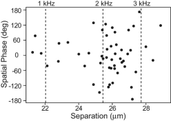
The relative phase of two split condensates turned out to be unpredictable when they were fully separated (Fig. 3). The separation of two condensates was determined from the spacing, , of the interference fringes, using the formula, where is Plank’s constant, is atomic mass, and is time-of-flight. The typical fringe spacing was m with ms, corresponding to m. Given the precise knowledge of the fabricated wires, the full trap parameters can be calculated. Assuming that the condensates followed trap centers in the motional ground state, it was found that when the barrier height was over 1.5 kHz, the relative phase started to be random. Since the chemical potential of the condensates, kHz was very close to this barrier height, the condensates just started to lose their coupling at this point.

Surprisingly, a phase singularity was observed in the interference patterns with high visibility. The fork shape of interference fringes represents a phase winding around a vortex core Inouye et al. (2001). This vortex interference pattern appeared more frequently with faster splitting and further separation. An external perturbation can lead to internal excitations in condensates. Splitting might be considered as slicing condensates in two parts. The fact that the observed “forks” (Fig. 4) always open towards the top implies that the the slicing always occurred in the same direction and created either vortices with positive charge on the left side or with negative charge on the right side. A possible vortex formation mechanism is topological imprinting when the zero point of the magnetic field crosses though condensates resulting in a doubly quantized vortex in spin-1 condensates Leanhardt et al. (2002b); Shin et al. (2004b). However, since we have never observed the interference pattern of a doubly quantized vortex, we think that this scenario is unlikely.
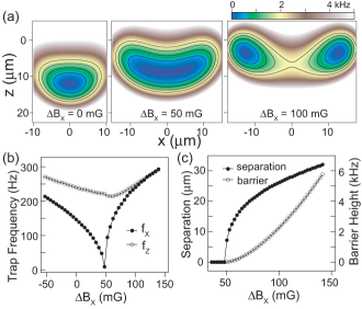
We now discuss how the trapping potential changes during the splitting process (Fig. 5). When condensates split into two wells, the trap frequency, , in the splitting direction vanishes and the separation of two wells abruptly increases to 15 m with a small magnetic field change of mG. The quantity parameterizes the external adiabaticity of the process for a single particle, neglecting the collective excitations of a condensate, and should be maintained to keep condensates staying in the motional ground state. With G/s, at Hz, but obviously, diverges to infinity near the merge point, implying that the quartic potential with zero trap frequency makes it impossible to satisfy the adiabatic condition during the whole splitting process. The abrupt change of trapping potential will induce mechanical perturbations of condensates. Subsequent dissipation or coupling into internal excitation modes Ott et al. (2003) would make the relative phase of two split condensates unpredictable. The observed phase singularity definitely shows the breakdown of adiabaticity.
One possible alternative to avoid passing through the merge point is starting with two weakly-linked condensates in a double-well potential where the barrier height is lower than the chemical potential of condensates and controlling the coupling between two condensates with a small change of the barrier height. This method was used to reduce the motional perturbation in our previous work Shin et al. (2004a). However, since the sensitivity of the trapping potential to the magnetic field is extremely high when the trap centers are close to the merge point, it was technically difficult to have a stable double-well potential with a small barrier height. The lifetime of condensates measured around the merge point was s away from the merge point ( mG or mG) and ms near the merge point ( mG) 222For positions with (“after” splitting), the condensates were moved to the left well without passing through the merge point.. With a barrier height of 0.5 kHz in our experiment, the sensitivity of the barrier height and the condensate separation to is 0.04 kHz/mG and 0.3 m/mG, respectively. mG corresponds to A. Extreme current stabilization and shielding of ambient magnetic field fluctuations may be necessary for controlling a phase-coherent splitting process. Another alternative for preparing a coherent state of two spatially separated condensates is first preparing two condensates in the ground states in each well and then establishing a well-defined relative phase with an optical method Saba et al. (2005). This scheme is currently under investigation.
In conclusion, we demonstrated the interference of two Bose-Einstein condensates released from an atom chip. The condensates were created by dynamical splitting of a single condensate and could be kept confined in a magnetic double well potential, separated by an arbitrary distance. We studied the coherence of the dynamical splitting process by measuring the relative phase of two split condensates and identified technical limitations, intrinsic to the magnetic field geometry, that prevented coherent splitting with a predictable phase. This study is a promising step in the route towards atom chip interferometers and might serve as a guide for the design of future microfabricated atom optics device.
This work was funded by ARO, NSF, ONR, DARPA and NASA. C.S. acknowledges additional support from the Studienstiftung des deutschen Volkes, G.-B. J. from the Samsung Lee Kun Hee Scholarship Foundation, and M.S. from the Swiss National Science Foundation.
References
- Müller et al. (1999) D. Müller et al., Phys. Rev. Lett. 83, 5194 (1999); N. H. Dekker et al., Phys. Rev. Lett. 84, 1124 (2000); R. Folman et al., Phys. Rev. Lett. 84, 4749 (2000).
- Ott et al. (2001) H. Ott, J. Fortagh, G. Schlotterbeck, A. Grossmann, and C. Zimmermann, Phys. Rev. Lett. 87, 230401 (2001).
- Hänsel et al. (2001) W. Hänsel, P. Hommelhoff, T. W. Hänsch, and J. Reichel, Nature 413, 498 (2001).
- Leanhardt et al. (2002a) A. E. Leanhardt, A. P. Chikkatur, D. Kielpinski, Y. Shin, T. L. Gustavson, W. Ketterle, and D. E. Pritchard, Phys. Rev. Lett. 89, 040401 (2002a).
- Fortágh et al. (2002) J. Fortágh, H. Ott, S. Kraft, A. Günther, and C. Zimmermann, Phys. Rev. A 66, 041604(R) (2002).
- Leanhardt et al. (2003) A. E. Leanhardt, Y. Shin, A. P. Chikkatur, D. Kielpinski, W. Ketterle, and D. E. Pritchard, Phys. Rev. Lett. 90, 100404 (2003).
- Jones et al. (2003) M. P. A. Jones, C. J. Vale, D. Sahagun, B. V. Hall, and E. A. Hinds, Phys. Rev. Lett. 91, 080401 (2003).
- Estève et al. (2004) J. Estève, C. Aussibal, T. Schumm, C. Figl, D. Mailly, I. Bouchoule, C. I. Westbrook, and A. Aspect, Phys. Rev. A 70, 043629 (2004).
- Wang et al. (2005) Y.-J. Wang, D. Z. Anderson, V. M. Bright, E. A. Cornell, Q. Diot, T. Kishimoto, M. Prentiss, R. A. Saravanan, S. R. Segal, and S. Wu, Phys. Rev. Lett. 94, 090405 (2005).
- Martin et al. (1988) P. J. Martin, B. G. Oldaker, A. H. Miklich, and D. E. Pritchard, Phys. Rev. Lett. 60, 515 (1988).
- Olshanii and Dunjko (2005) M. Olshanii and V. Dunjko, cond-mat/0505358 (2005).
- Javanainen and Wilkens (1997) J. Javanainen and M. Wilkens, Phys. Rev. Lett. 78, 4675 (1997).
- Leggett and Sols (1998) A. J. Leggett and F. Sols, Phys. Rev. Lett. 81, 1344 (1998).
- Menotti et al. (2001) C. Menotti, J. R. Anglin, J. I. Cirac, and P. Zoller, Phys. Rev. A 63, 023601 (2001).
- Pezzé et al. (2004) L. Pezzé, A. Smerzi, G. P. Berman, A. R. Bishop, and L. A. Collins, cond-mat/0411567 (2004).
- Shin et al. (2004a) Y. Shin, M. Saba, T. A. Pasquini, W. Ketterle, D. E. Pritchard, and A. E. Leanhardt, Phys. Rev. Lett. 92, 050405 (2004a).
- Hinds et al. (2001) E. A. Hinds, C. J. Vale, and M. G. Boshier, Phys. Rev. Lett. 86, 1462 (2001).
- Groth et al. (2004) S. Groth, P. Krüger, S. Wildermuth, R. Folman, T. Fernholz, J. Schmiedmayer, M. Mahalu, and I. Bar-Joseph, Appl. Phys. Lett. 85, 2980 (2004).
- Shin et al. (2004b) Y. Shin, M. Saba, M. Vengalattore, T. A. Pasquini, C. Sanner, A. E. Leanhardt, M. Prentiss, D. E. Pritchard, and W. Ketterle, Phys. Rev. Lett. 93, 160406 (2004b).
- Leanhardt et al. (2002b) A. E. Leanhardt, A. Görlitz, A. P. Chikkatur, D. Kielpinski, Y. Shin, D. E. Pritchard, and W. Ketterle, Phys. Rev. Lett. 89, 190403 (2002b).
- Inouye et al. (2001) S. Inouye, S. Gupta, T. Rosenband, A. P. Chikkatur, A. Görlitz, T. L. Gustavson, A. E. Leanhardt, D. E. Pritchard, and W. Ketterle, Phys. Rev. Lett. 87, 080402 (2001).
- Ott et al. (2003) H. Ott, J. Fortágh, S. Kraft, A. Günther, D. Komma, and C. Zimmermann, Phys. Rev. Lett. 91, 040402 (2003).
- Saba et al. (2005) M. Saba, T. A. Pasquini, C. Sanner, Y. Shin, W. Ketterle, and D. E. Pritchard, Science 307, 1945 (2005).