Bose-Einstein condensation in a circular waveguide
Abstract
We have produced Bose-Einstein condensates in a ring-shaped magnetic waveguide. The few-millimeter diameter non-zero bias ring is formed from a time-averaged quadrupole ring. Condensates which propagate around the ring make several revolutions within the time it takes for them to expand to fill the ring. The ring shape is ideally suited for studies of vorticity in a multiply-connected geometry and is promising as a rotation sensor.
Scalar superfluids are characterized by a complex order parameter which is uniquely defined throughout the fluid. This implies the irrotational motion of the fluid in the space where , leading to the Meissner effect in charged superfluids and to the Hess-Fairbank effect in neutral ones. Given this constraint, rotational motion of superfluids (or magnetic flux density in type-II superconductors) is accommodated by lines of quantized vorticity which disrupt the simple connectivity of the fluid. Multiple connectivity can also be imposed by the proper design of containers for the fluids. Such geometries are enlisted to translate phase variations of into sensors of external fields. For example, a SQUID magnetometer makes use of a superconducting ring interrupted by Josephson junctions to allow continuous sensitivity to magnetic fields. A similar geometry was used in a superfluid 3He gyroscope schw97 .
Dilute gas superfluids enable novel forms of matter-wave interferometry. Precise sensors of rotation, acceleration, and other sources of quantal phases petr99 ; lyan00 using trapped or guided atoms have been envisioned. In particular, the sensitivity of atom-interferometric gyroscopes is proportional to the area enclosed by the closed loop around which atoms are guided gust00sagnac . Such considerations motivate the development of closed-loop atom waveguides which enclose a sizeable area.
A number of multiply-connected trapping geometries for cold atoms have been discussed. Optical traps using high-order Gauss-Laguerre beams were proposed wrig00 ; ande03 , and hollow light beams were used to trap non-degenerate atoms in an array of small-radius rings verk03 . Large-scale magnetic “storage rings” were developed for cold neutrons kugl85 and discussed for atomic hydrogen thom89 . More recently, closed-loop magnetic waveguides were demonstrated for laser cooled atoms saue01 ; wu04guide . Unfortunately, these guides are characterized by large variations in the potential energy along the waveguide and by high transmission losses at points where the magnetic field vanishes.
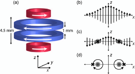
In this Letter, we report the creation of a smooth, stable circular waveguide for ultracold atoms. A simple arrangement of coaxial electromagnetic coils was used to produce a static ring-shaped magnetic trap, which we call the quadrupole ring (Qring), in which strong transverse confinement is provided by a two-dimensional quadrupole field. Atoms trapped in the Qring experience large Majorana losses, but we can eliminate such losses with a time-orbiting ring trap (TORT) arno04tort . In this manner, stable circular waveguides with diameters ranging from 1.2 to 3 mm were produced. Finally, we report on the production of Bose-Einstein condensates (BECs) in a portion of the circular waveguide, and on the guiding of an ultracold atomic beam for several revolutions around the guide. This ring-shaped trap presents opportunities for studies of BECs which are homogeneous in one dimension and therefore of the unterminated propagation of sound waves andr97prop and solitons sala99toroid ; bran01 ; mart01 , of persistent currents bloc73 ; java98pers ; bena99 ; nuge03 , of quantum gases in low dimensions, and of matter-wave interferometry.
To explain the origin of the quadrupole ring trap, we consider a cylindrically-symmetric static magnetic field in a source-free region. Expanding to low order about a point (taken as the origin) on the axis where the field magnitude has a local quadratic minimum, we have
| (1) |
where is the field magnitude at the origin, the axial field curvature, and with cartesian coordinates (,,) chosen so that is the axial coordinate. The magnetic field magnitude falls to zero in the - plane along a circle of radius centered at the origin. This is the Qring, a ring-shaped magnetic trap for weak-field seeking atoms. Near the field zeros, the magnetic field has the form of a transverse (radial and axial directions) two-dimensional quadrupole field with gradient . Such traps can also be obtained using different electromagnet configurations arno04tort .
In our apparatus, the Qring is formed using a subset of the coils (the curvature and anti-bias coils, see Fig. 1) used in our recently demonstrated millimeter-scale Ioffe-Pritchard magnetic trap moor05 . Our work is aided in particular by the large axial curvatures produced in this trap and by the vertical orientation of the trap axis. These features are relevant for the operation of a Qring in the presence of gravity, for two reasons. First, trapping atoms in the Qring requires transverse confinement sufficient to overcome the force of gravity; this places a lower bound on the radius of the Qring of with the atomic mass, the acceleration due to gravity, and the atomic magnetic moment. Indeed, if exceeds the range over which Eq. 1 is valid, typically the distance to the field-producing coils, the formation of a Qring may be precluded entirely. With G/cm2 in our experiments, m is much smaller than the millimeter dimensions of the electromagnets used for the trap. Second, the vertical orientation of the Qring axis allows cold atoms to move slowly along the nearly horizontal waveguide rather than being confined in a deep gravitational well.
Atoms can be localized to a particular portion of the Qring by application of a uniform sideways (in the - plane) magnetic field; e.g. a weak bias field tilts the Qring by about the axis. This adjustment also adds an azimuthal field of magnitude , splitting the Qring into two trap minima at opposite sides of the ring, with being the azimuthal angle conventionally defined.
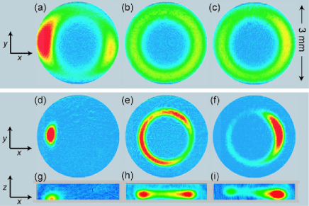
We loaded cold atoms into the Qring using a procedure similar to previous work moor05 . Briefly, about 87Rb atoms in the hyperfine ground state were loaded into one of two adjacent spherical quadrupole magnetic traps. Using these traps, atoms were transported 3 inches from the loading region to the Qring trap region. During this transport, RF evaporative cooling was applied, yielding atoms at a temperature of K in a spherical quadrupole trap with an axial field gradient of 200 G/cm. Within 1 s, we then converted the spherical quadrupole to a tilted-Qring trap produced with G/cm2, G, and a side field of magnitude G. This process left atoms trapped in the Qring (Fig. 2).
The trapping lifetime of atoms in the Qring is limited by Majorana losses. In a balanced Qring, trapped atoms passing close to the line of zero field, which extends all around the ring, may flip their spins and be expelled from the trap. Extending the treatment by Petrich et al. petr95 to this scenario, we estimate a Majorana loss rate of for our trap at a temperature of 60 K. In a tilted Qring, the zero-field region is reduced to just two points at opposite sides of the ring. Majorana losses in a tilted Qring are thus similar to those in spherical quadrupole traps and much smaller than in a balanced Qring. We confirmed this qualitative behaviour by measuring the lifetime of trapped atoms in balanced and tilted Qring traps. In the balanced Qring, the measured 0.3 s-1 Majorana loss rate was thrice that in a tilted Qring, while falling far short of the predicted 6 s-1 loss rate, presumably due to residual azimuthal fields.
The high loss rates in the Qring can be mended in a manner similar to the time-orbiting potential (TOP) trap by which Majorana losses in a spherical quadrupole field were overcome petr95 . As proposed by Arnold arno04tort , a time-orbiting ring trap (TORT) with non-zero bias field can be formed by displacing the ring of field zeros away from and then rapidly rotating it around the trapped atoms (Fig. 1(c)). From Eq. 1, the Qring can be displaced radially by application of an axial bias field, and displaced along by a cylindrically-symmetric spherical quadrupole field. The TORT provides transverse quadratic confinement with an effective field curvature of , where is the magnitude of the rotating field seen at the trap minimum. Just as the TOP trap depth is limited by the “circle of death,” the TORT trap depth is limited by a “torus of death,” the locus of points at which the magnetic field is zero at some time evapfootnote . This scheme may be applied equally to a tilted Qring, yielding a tilted TORT and providing a stable trap in which atoms are confined to a portion of the ring. The sideways magnetic field (e.g. along ) causes the magnetic potential minimum to vary azimuthally in the tilted TORT as . The variation in the gravitational potential is the same as that in a Qring.
The time-varying fields needed to convert our Qring (or tilted Qring) traps to TORT (or tilted TORT) traps were obtained by suitably modulating the currents in the four coils used to generate the Qring potential. A modulation frequency of kHz was chosen to be much larger than the transverse motional frequencies (Hz) and also much smaller than the Larmor frequency (MHz) at the location of the trap minimum. To first switch on the TORT, a rotating field magnitude of G was used brotfootnote .
As shown in Fig. 3, the trap lifetime was dramatically increased by application of the TORT trap. In the first few seconds after switching on the TORT, we observed a fast loss of atoms and a simultaneous drop in their temperature. We ascribe this loss and cooling to the evaporation of atoms from the trapped cloud through the “torus of death.” As the temperature dropped, the evaporation rate diminished and lifetime of trapped atoms became vacuum limited at 90 s, a value observed both for balanced and for tilted TORT traps.
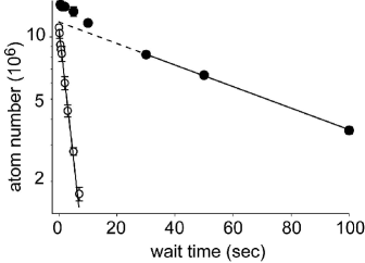
Given their longevity, it is possible to evaporatively cool TORT-trapped atoms to the point of quantum degeneracy. Using a tilted TORT with G, evaporation was performed in two stages. First, “torus of death” evaporation was applied by ramping down the rotating field strength over 40 s to G. The oscillation frequencies in this trap were measured as Hz in the transverse and Hz in the azimuthal directions, in agreement with predictions transversefootnote . In the second stage, RF evaporation was applied for 20 s, yielding clouds of up to atoms at the Bose-Einstein condensation temperature, and pure BECs of up to atoms.
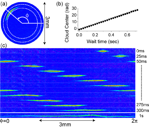
Finally, to assess the suitability of the TORT as an atomic waveguide for interferometry, we launched our trapped BECs into closed-loop circular motion along the guide. This was accomplished by reorienting the sideways bias field , inducing the trapped BEC to accelerate toward the newly-positioned tilted TORT trap minimum (advanced by an azimuthal angle of about ), while simultaneously reducing the magnitude of to and increasing to 12.6 G to produce a well-balanced TORT trap. The TORT was then maintained at this setting, with radius mm ( G, G/cm2), and transverse trap frequencies of Hz as measured at the launch-point of the atoms. The atoms were allowed to propagate freely around the guide for various guiding times before being observed by absorption imaging. As shown in Fig. 4, the ultracold atomic beam propagated around the circular waveguide at an angular (linear) velocity of 40.5 rad/s (50.6 mm/s). As measured from the the azimuthal extent of the atoms for different guiding times, this pulsed atom beam was characterized by an azimuthal rms velocity spread of 1.4 mm/s, equivalent to a longitudinal temperature of 22 nK. After about 1 s of guiding, this velocity variation caused the atomic cloud to spread throughout the waveguide, by which point the atoms had travelled mm along the waveguide, encompassing an area of mm2.
Many requisite elements for interferometric rotation sensing are still lacking in our system, including a means of in-guide coherent atomic beam splitting wang05inter ; wu05debroglie , bidirectional propagation, proper radial waveguiding ande02multi , full characterization of longitudinal coherence in the beam, an assessment of the influence of the time-orbiting field on sensor precision, and atom-interferometric stability. Nevertheless, it is valuable to consider the possible sensitivity of our system if these elements are attained. As limited by atomic shot-noise, rotation measurements with an uncertainty of rad/s could be made from a single (1 s long) measurement, where is the number of atoms used. While this figure is nearly 20 times that of existing atom-based gyroscopes gust00sagnac , improvements such as launching the atoms at higher velocities, increasing the TORT radius, and increasing the atom number may ultimately yield a useful, compact sensing device.
Other applications of the TORT may include studies of propagation bong01guide ; lean02guide ; fort03guide and non-linear dynamics ott03guide in atomic waveguides. In a TORT potential which is modified either by application of magnetic fields or by tilting with respect to gravity, BEC’s can be studied both undergoing pendular motion (terminated guide) when launched at small velocities, and undergoing circular motion (unterminated guide) at larger velocities.
Another appealing possibility is the study of BECs which fill the ring-shaped trap, rather than forming in just a portion of the ring. Such a system would allow for studies of quantized and persistent circulation bloc73 ; java98pers ; bena99 ; nuge03 , unterminated motion of solitons sala99toroid ; bran01 ; mart01 , and other aspects of non-linear dynamics gara00hole . For this purpose, the azimuthal variation in the TORT potential must be reduced below the typical nK scale of the BEC chemical potential. From measurements of the kinetic energy of BEC’s undergoing circular motion in our trap (data of Fig. 4), we estimate the TORT potential varied by as much as 5 K. We believe this figure can be reduced greatly by using traps of smaller radius, by designing better electromagnets both for the static and the rotating fields used for the TORT, and also by controlling the orientation of the electromagnets with respect to gravity.
This work was sponsored by DARPA (Contract No. F30602-01-2-0524), the NSF (Grant No. 0130414), the David and Lucile Packard Foundation, and the University of California. KLM acknowledges support from the NSF, and SG from the Miller Institute.
References
- (1) K. Schwab, N. Bruckner, and R. E. Packard, Nature 386, 585 (1997).
- (2) K. G. Petrosyan and L. You, Phys. Rev. A 59, 639 (1999).
- (3) Y. Lyanda-Geller and P. M. Goldbart, Phys. Rev. A 61, 043609 (2000).
- (4) T. Gustavson, A. Landragin, and M. Kasevich, Classical and Quantum Gravity 17, 2385 (2000).
- (5) E. M. Wright, J. Arlt, and K. Dholakia, Phys. Rev. A 63, 013608 (2000).
- (6) B. P. Anderson, K. Dholakia, and E. M. Wright, Phys. Rev. A 67, 033601 (2003).
- (7) P. Verkerk and D. Hennequin, preprint, arXiv:physics/0306155.
- (8) K.-J. Kügler, K. Moritz, W. Paul, and U. Trinks, Nucl. Instrm. Methods 228, 240 (1985).
- (9) D. Thompson, R. V. E. Lovelace, and D. M. Lee, J. Opt. Sci. Am. B 6, 2227 (1989).
- (10) J. A. Sauer, M. D. Barrett, and M. S. Chapman, Phys. Rev. Lett. 87, 270401 (2001).
- (11) S. Wu, W. Rooijakkers, P. Striehl, and M. Prentiss, Phys. Rev. A 70, 013409 (2004).
- (12) A. S. Arnold, J. Phys. B 37, L29 (2004).
- (13) M. R. Andrews et al., Phys. Rev. Lett. 79, 553 (1997).
- (14) L. Salasnich, A. Parola, and L. Reatto, Phys. Rev. A 59, 2990 (1999).
- (15) J. Brand and W. P. Reinhardt, J. Phys. B 34, L113 (2001).
- (16) J.-P. Martikainen et al., Phys. Rev. A 64, 063602 (2001).
- (17) F. Bloch, Phys. Rev. A 7, 2187 (1973).
- (18) J. Javaneinen, S. M. Paik, and S. M. Yoo, Phys. Rev. A 58, 580 (1998).
- (19) M. Benakli et al., Europhysics Letters 46, 275 (1999).
- (20) E. Nugent, D. McPeake, and J. F. McCann, Phys. Rev. A 68, 063606 (2003).
- (21) K. L. Moore et al., preprint, arXiv:cond-mat/0504010.
- (22) W. Petrich, M. H. Anderson, J. R. Ensher, and E. A. Cornell, Phys. Rev. Lett. 74, 3352 (1995).
- (23) Due to this topology, RF evaporation should be equally effective whether one approaches the Larmor frequency at the trap minimum from above or below.
- (24) The magnitude of ranged between and 20 G during the 5 kHz modulation.
- (25) The transverse asymmetry arises due the sideways field . In the tilted-TORT, considering both magnetic and gravitational potentials, the azimuthal trap frequency is .
- (26) Y.-J. Wang et al., Phys. Rev. Lett. 94, 090405 (2005).
- (27) S. Wu, E. J. Su, and M. Prentiss, preprint, arXiv:cond-mat/0503130.
- (28) E. Andersson et al., Phys. Rev. Lett. 88, 100401 (2002).
- (29) K. Bongs et al., Phys. Rev. A 63, 031602 (2001).
- (30) A. E. Leanhardt et al., Phys. Rev. Lett. 89, 040401 (2002).
- (31) J. Fortà gh et al., Applied Physics B: Lasers and Optics 76, 157 (2003).
- (32) H. Ott et al., Phys. Rev. Lett. 91, 040402 (2003).
- (33) L. J. Garay, J. R. Anglin, J. I. Cirac, and P. Zoller, Phys. Rev. Lett. 85, 4643 (2000).