Crucial role of side walls for granular surface flows: consequences for the rheology
Abstract
In this paper we study the steady uniform flows that develop when granular material is released from a hopper on top of a static pile in a channel. We more specifically focus on the role of side walls by carrying out experiments in setup of different widths, from narrow channels 20 particle diameters wide to channels 600 particle diameters wide. Results show that steady flows on pile are entirely controlled by side wall effects. A theoretical model, taking into account the wall friction and based on a simple local constitutive law recently proposed for other granular flow configurations ([GDR MiDi 2004]), gives predictions in quantitative agreement with the measurements. This result gives new insights in our understanding of free surface granular flows and strongly supports the relevance of the constitutive law proposed.
1 Introduction
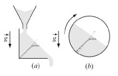
Grains avalanching on a sand heap are often presented as the archetype of granular flows. In this situation both the liquid and solid behaviours of granular material coexist. The flow is confined in a thin layer of grains, typically few grain diameters, flowing at the free surface of a pile formed by static grains. Despite the apparent simplicity of the configuration, its description still represents a serious challenge as it gathers in a single flow all the difficulties specific to granular material. How can we describe the transition between the liquid and the solid behaviour? How is the thickness of the flowing layer selected? What kind of constitutive laws can describe the flow characteristics? These questions have motivated many experimental works in the ten last years. Two different configurations have been used to create surface granular flows: the flow on a heap and the rotating drum (figure 1). In the first one, the granular material is released from a hopper on top of a pile. The control parameter is the flow rate. The second one is a cylinder half filled with the granular material. In this case, the control parameter is the rotation speed that indirectly controls the flow rate of the flowing layer. In both configurations, the flow characteristics are similar and can be summarized as follow:
(i) A minimum flow rate (or rotation rate in the rotating drum) exists below which the flow is intermittent and proceeds as successive avalanches. Above this threshold, a steady regime is observed ([Rajchenbach 1990]; [Lemieux & Durian 2000]).
(ii) In the steady regime, the free surface inclination, sometimes called the dynamical angle of friction, increases when increasing the flow rate ([Khakhar et al. 2001]; [Ancey 2001]; [Taberlet et al. 2003]; [GDR MiDi 2004]).
(iii) In the steady regime, the velocity profile (often measured at the side wall) is localized at the free surface, with a linear profile at the top followed by an exponential tail ([Komatsu et al. 2001]; [GDR MiDi 2004]). The shear rate in the flowing region is of order where is the gravity and the particle diameter, this shear rate being weakly dependent on the flow rate ([Rajchenbach 1990]; [Khakhar et al. 2001]; [Bonamy, Daviaud & Laurent 2002]).
Based on these observations, several theoretical approaches have been proposed. Some are based on the analysis of individual grains motion, showing that a linear profile localized at the free surface could be explained by the dissipative nature of collisions ([Andreotti & Douady 2001]; [Rajchenbach 2003]; [Hill, Gioia & Tota 2003]). Others are hydrodynamic descriptions based on different rheological constitutive laws ([Elperin & Vikhanski 1998]; [Khakhar et al. 2001]; [Bonamy, Daviaud & Laurent 2002]; [Josserand, Lagrée & Lhuillier 2004]). In all these attempts to describe free surface flows, the influence of side walls is neglected. The experimental measurements are interpreted as if the side walls, often made of smooth surfaces, do not play a major role in the flow dynamics.
However, this assumption is far from being straightforward and to our opinion warrants a deeper investigation. Some signs exist in the literature showing that side walls could have a crucial role in the dynamics of surface granular flows. The most striking evidence concerns the inclination angle of the free surface with respect to horizontal. In the intermittent avalanching regime, experimental works have shown that angles at which avalanches start or stop strongly depend on the width between lateral walls ([Grasselli & Herrmann 1997]; [Zhou et al. 2002]). In the continuous flowing regime, experiments carried out in long rotating drums have shown that the surface inclination is few degrees higher close to the wall than in the middle of the drum ([Dury et al. 1998]; [Yamane et al. 1998]). More recently, some studies of flow on a heap have revealed the existence of surprisingly steep piles at high flow rates in narrow channels ([Taberlet et al. 2003]). This angle made by the free surface with horizontal controls the stress distribution in the material. As a consequence, if side walls have a strong influence on the inclination, it is legitimate to wonder to what extent they do not dramatically also modify the flow characteristics, such as the flow thickness and the velocity profiles. However, most of the experiments are carried out in narrow devices, with a gap between side walls less than 30 particle diameters. Very few studies are made in wide rotating drums configuration and none in wide heap configuration. What does happen in the case of large system? Are flow characteristics going to change? Does the influence of side walls disappear for large enough system?
Answering these questions on the role of side walls for granular surface flows represents the first goal of this study. Once we know if side walls can be neglected or not and what is their influence, it will be possible to properly use the surface flow configuration to test constitutive equations for dense granular flows. This is the second goal of this study, where we shall test an empirical rheology recently proposed for other configurations.
In a recent collective work ([GDR MiDi 2004]), data from different configurations and from different research groups have been collected. A local rheology has been proposed, which was able to unify results numerically obtained on plane shear ([Chevoir et al. 2004]; [Iordanoff & Khonsari 2004]; [Da Cruz et al. 2004]) and results obtained both in experiments and in simulations for flows down inclined planes ([Pouliquen ]; [Chevoir et al. 2001]; [Pouliquen & Forterre 2002]; [Silbert, Landry & Grest 2003]; [Forterre & Pouliquen 2003]). The rheology is written has a friction law, i.e. the shear stress is proportional to the normal stress, with a coefficient of friction depending on a dimensionless shear rate. Although this local approach suffers from several limits which are discussed in GDR MiDi (2004), the fact that a single law correctly describes two different configurations, the plane shear and the inclined plane, is to our opinion very encouraging and deserves a deeper confrontation with other flow configurations. In that sense, granular surface flows represent a severe test for this local rheology as they exhibit peculiar flow characteristics, e.g. localized velocity profiles, that strongly contrast with those observed in plane shear or inclined plane configurations.
The aims of this study are then, first to clarify the role of side walls for granular surface flows and second, to test the local constitutive law proposed recently in GDR MiDi (2004). The configuration we choose is the flow on a heap (figure 1a). This choice rather than the rotating drum configuration is motivated by the fact that steady uniform flows, i.e. with a flowing thickness independent of the distance to the hopper, can be obtained for heap flows whereas in rotating drums the thickness varies along the flow. For this configuration we systematically investigate the role of side walls by making experiments in channels of different widths from a quasi 2-D configuration (20 particle diameters) to a very wide situation (600 particle diameters). We then compare our measurements of the free surface inclination, the free surface velocity and the flow thickness in the steady uniform regime to the prediction of the local rheology.
The paper is organized as follow. The experimental set-up and measurement methods are presented in section 2. The influence of the channel width on the steady uniform flow properties are presented in section 3. The theoretical approach based on the local rheology proposed recently in GDR MiDi (2004) is described in section 4, and the predictions are compared with measurements in section 5. Discussion and conclusion are given in section 6 and 7.
2 Experimental method
2.1 Experimental set-up
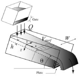
The experimental set-up is sketched in figure 2. We use glass beads of diameter mm as granular material. The box is 1.5 m long made of a rough bottom plate and two smooth lateral glass walls. The gap between the side walls can be changed from 1 cm () up to 30 cm (). The box is closed at the bottom end by a 10 cm height plate. In order to use less granular material, the whole set up is inclined at an angle less than the angle of repose of the material, so that, when the box is filled, the static layer is everywhere thicker than 10 cm (). On top of this static layer we release particles from a hopper placed at the top of the channel. The flow rate is controlled by the opening of the gate. The experimental procedure is the following. At the beginning of each experiment the box is empty. When opening the gate of the hopper, the beads first fill the box before flowing over the end plate when the box is full. For high enough flow rates, a steady regime then develops with a layer of grains flowing on top of a static pile. All the measurements presented in the following are done in the steady regime.
In this regime, far from the entrance and the exit, the flow is uniform along the -direction. The free surface make a constant angle with the horizontal and is almost flat in the transverse direction (its variations between the wall and the middle are less than 2 grain diameters). The free surface velocity is aligned along the -direction, the transverse velocity being less than 1% of the longitudinal one, and. The free surface velocity is also uniform along the -direction however it varies in the transverse y-direction: the flow is faster in the middle of the channel. The thickness of the flowing layer also varies in the -direction and is larger in the middle than at the walls. In order to characterize the flow, four quantities are measured: the mean flow rate per unit of width (m2/s) (in the following we simply call the “flow rate”), the inclination of the free surface with horizontal , the thickness of the flowing layer measured in the centre line of the channel, and the free surface velocity field . It must be emphasized that, in this configuration, the only control parameter is the mean flow rate fixed by the aperture of the hopper. The thickness , the velocity and the inclination are chosen by the system. It should be noticed that the control parameter is a flow rate averaged over the channel. The local flow rate is not uniform and is smaller close to the wall than in the middle of the flow.
2.2 Measurement methods
In order to measure , we weigh the mass flowing out of the channel during a finite time (between 30 s and 3 s) once the steady regime is reached. is then computed knowing the density of the beads kg/m3 and assuming the volume fraction of beads during the flow to be : . The inclination of the free surface is measured from a picture taken from the side and analyzed using image processing (software ImageJ available from the internet at http://rsb.info.nih.gov/ij/). The measurement precision is about . Velocity profiles are computed from movies recorded by a fast camera taken at rate between 250 and 1000 frames per second. The velocity profile is then obtained using a modified Particle Imaging Velocimetry (PIV) method. The precision is about mm/s. Finally we have to measure the flow thickness.
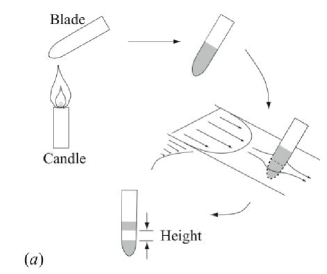
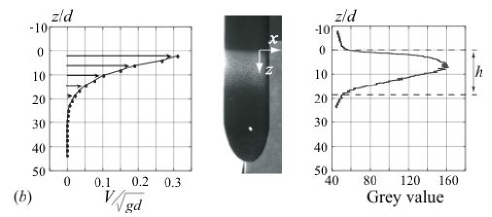
Since the granular material is opaque, we cannot measure in the bulk using a camera. In order to get an estimate of the flow thickness far from the walls, we have developed a weakly intrusive method based on erosion measurements. A thin metal blade, mm thick and 2 cm wide, is blackened with the flame of a candle. The blade is then suddenly immersed in the flow, perpendicular to the free surface and hold at a fixed position during 20 s before we remove it (figure 3a). We have checked that the upstream flow is hardly perturbed by the intrusion of the thin blade. Once the blade is removed, one observes that the black soot has been eroded in the region where the grains were flowing but not in regions where grains were static. In order to test the method we have put the blade close to the wall, where we can compare the erosion pattern with the depth velocity profile along measured using PIV. A typical result is shown in figure 3(b) where the centre picture shows the eroded blade lighted at a low incidence angle. The bright part corresponds to region eroded by the flow. The graph on the right is the intensity profile of the blade averaged over the width. For comparison we have plotted on the same figure the corresponding velocity profile (figure 3b left). The correlation of the erosion pattern and the velocity profile is good showing that the erosion method gives a good estimate of the flow thickness (see legend of figure 3).
3 Influence of the side walls on steady uniform flows
In order to precisely understand the influence of the side walls on granular surface flows, measurements are made for channel widths varying from 19 particle diameters to 570 particle diameters. For each width, the inclination , the thickness and the free surface velocity have been measured as a function of the flow rate . The results presented in the following are expressed in terms of dimensionless variables using the particle diameter and the gravity . The dimensionless flow rate is , the dimensionless thickness is , the dimensionless width is and the dimensionless velocities are .
3.1 Existence of steady uniform flows
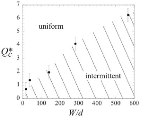
The first observation is that a minimum flow rate is necessary to obtained a steady flow ([Rajchenbach 1990]; [Lemieux & Durian 2000]). Below this critical value, the flow is intermittent and occurs by successive avalanches. Above this value, a steady regime is reached, where the outlet flow rate is constant and equal to the inlet flow rate. The interesting point we show here is that depends on the width of the channel as shown in figure 4. For wide channels, one needs to supply more grains per second and per unit of width to reach a stationary flow.
In the stationary regime, the spatial variation of the flow along the slope is as follows. The grains falling from the hopper first accelerate at the top of the pile, before reaching a steady velocity. About 10 cm from the outlet, they accelerate again and fall over the end plate. In between the entrance and the outlet regions, the flow is then uniform independent of the position. All the measurements presented below are done in this steady and uniform regime.
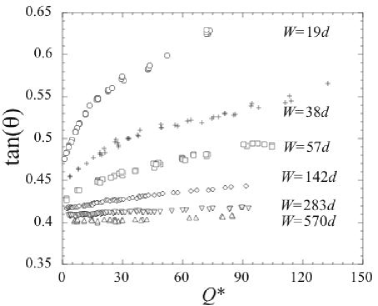
3.2 Free surface inclination
As observed in previous studies ([Rajchenbach 1990]; [Dury et al. 1998]; [Yamane et al. 1998]; [Grasselli & Herrmann 1999]; [Lemieux & Durian 2000]; [Khakhar et al. 2001]), the angle between the free surface and the horizontal increases when increasing the flow rate as shown in figure 5. However, although this effect is important for narrow channels, it almost disappears for the widest channel we have investigated. For , the surface slope remains almost constant close to the angle of repose of our material. This clearly shows that the increase of the slope with flow rate is due to the additional friction induced by the side walls as mentioned in several previous studies ([Taberlet et al. 2003]; [Courrech du Pont et al. 2003]; [GDR MiDi 2004]).
3.3 Free surface velocity
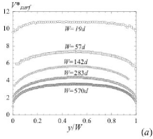
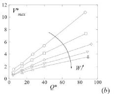
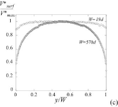
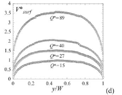
In order to investigate the influence of the channel width on the free surface velocity, we first perform experiments keeping the same flow rate per unit of width but changing the gap between the side walls. Figure 6(a) shows the transverse surface velocity profiles for . In these figures the transverse direction is rescaled by the channel width. The striking result is that the wider the channel, the slower the flow. By increasing the width from to , the velocity is divided by a factor three. This effect is observed for all the flow rates as shown in figure 6(b). In this figure, the velocity in the centre line () is plotted as a function of the flow rate for the different widths. The velocity increases with respect to the flow rate but decreases when increasing the width. The last important remark about the surface velocity profile is that profiles are less and less uniform in the transverse direction when enlarging the channel. Whereas for a plug region with a constant velocity exists far from the walls, this is no longer the case for (figure 6c). In this widest channel, the profile is curved all across the channel whatever the flow rate is as shown in figure 6(d). Therefore enlarging the channel does not allow to get rid of wall effects, contrary to what one would expect.
3.4 Thickness of the flow
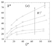
We have seen above that, for a given flow rate per unit of width, the flow velocity decreases when enlarging the channel. Because of mass conservation this implies that the flow should be thicker. This is verified by our measurements of the thickness in the middle of the channel () using the erosion method. In figure 7(a), we have plotted how the thickness varies as a function of the flow rate for different channel widths . The flow thickness increases with the flow rate but as expected from the velocity measurements, it also increases with . Surprisingly, for the widest channel the flow thickness reaches unusual high values about 75 grain diameters, much higher than the classical 10 or 20 particle diameters usually reported in the literature ([GDR MiDi 2004]). Concerning the variations of along , no systematic measurement of the profile has been made. However, we have noticed a similar tendency than for the free surface velocity. For narrow channels, the flowing thickness is uniform across the width, whereas for wide channels, variations are observed: is smaller close to the wall than in the center part. For example for and , in the centreline of the channel but is only at the wall.
3.5 Discussion
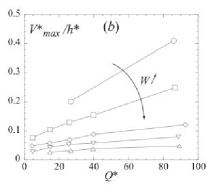
Whereas for narrow channels we recover results presented in the literature, e.g. increase of inclination with flow rate, flowing layer about ten particle diameters thick, our measurements in wide channels dramatically contrast with the previous studies. The major difference is that the flow occurs on much thicker layer and at a much lower velocity in wide channels than in narrow channels. This is in contradiction with the result commonly admitted for free surface flows that the shear rate in the flowing region of order of and weakly depends on the flow rate ([Khakhar et al. 2001]; [Bonamy, Daviaud & Laurent 2002]; [Rajchenbach 2003]; [GDR MiDi 2004]). This is clearly shown in figure 7(b) where we have plotted an estimate of the shear rate as a function of the flow rate . Although for narrow channels the shear rate is of order , it is almost 10 times lower in the widest channel. Moreover, figure 7(b) shows that the shear rate is not constant and obviously depends both on the flow rate and on the channel width .
This systematic study in channels of different widths therefore shows that side walls play a crucial role in the dynamics of granular flows on a pile. It seems impossible to get rid of them by enlarging the system. This observation suggests that it is essential to take into account side walls if one wants to model granular surface flows, at least in the steady regime. In the following we derive a theoretical model based on an empirical rheology recently proposed to describe dense granular flows, which takes into account additional wall friction, and compare the predictions with our experimental results.
4 Theoretical model
4.1 Choice of the rheology
In order to describe our surface flows, we need first to know the material rheology. Although the question of constitutive equations for dense granular flows is still a matter of debate, recent works in different configurations seem to converge and allow to propose a simple empirical rheology ([GDR MiDi 2004]).
The first information comes from the inclined plane configuration, when a granular layer flows down an inclined bumpy surface. The study of the steady uniform flows for which scaling laws have been observed ([Pouliquen ]; [Silbert, Landry & Grest 2003]), allows to propose an empirical friction law to describe the shear stress that develops at the interface between the flowing layer and the rough surface. This law stipulates that the shear stress is proportional to the weight of the layer times a friction coefficient which depends on both the layer thickness and the mean depth-averaged velocity . Based on the experimental measurements, the following form has been proposed for the basal friction coefficient ([Pouliquen & Forterre 2002]):
| (1) |
where is the particle diameter, the gravity and , , and are constants that depend on the material. This law has been successfully applied in the framework of depth-averaged equations to quantitatively predict the spreading of a granular mass ([Pouliquen & Forterre 2002]) and the development of instabilities ([Forterre & Pouliquen 2003]). However, it cannot be considered as a constitutive law since it only applies at the base of the layer.
The link with the rheology has been made only recently ([GDR MiDi 2004]), when comparing these results with numerical studies in the configuration of the plane shear cell (Da Cruz et al. 2004; Iordanoff & Khonsari 2004). In this configuration, a granular layer is confined between two rough plates under a confining pressure and sheared at a shear rate . The numerical simulations reveal that the shear stress verifies a friction law and that the friction coefficient depends on a single dimensionless parameter . can be interpreted as the ratio between the time scale given by the shear rate and the time scale related to the confining pressure ([GDR MiDi 2004]). The relation between shear stress and shear rate is then written in the following form:
| (2) |
where is the particle diameter and is the particle density.
The interesting result arises when comparing this relation with the one obtained on the inclined plane for the basal friction law (1). If one assumes that the material is everywhere defined by the local constitutive law given by relation (2), predictions can be made for flows on inclined planes (see appendix A). One can then show that the predictions are compatible with the basal friction law (1) issued from experimental measurements only if one chooses for the function the following form:
| (3) |
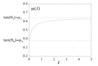
The coefficients and are the same as in relation (1) and the constant is related to the coefficient and in (1) (see appendix A). According to this law the friction coefficient goes from a minimum value for very low up to an asymptotical value when increases as sketched in figure 8.
By interpreting the basal friction law found in inclined plane experiments in the framework of the constitutive law found in plane shear, we are then able to propose a simple local rheology. The next step is to ask whether this rheology, which correctly describes plane shear and flows on inclined planes, can also predict surface flows on heaps. In the following, we apply relations (2) and (3) to heap flows taking into account the friction with side walls, and we compare the predictions with the experimental results presented in the previous section. In order to do so, we have to quantitatively determine the coefficients of the constitutive law (3). The glass beads used in our study being the same as the ones used by Forterre and Pouliquen (2003) in an inclined plane experiment, we can easily compute the coefficients of the relation from the coefficients that have been measured for the basal friction law. We found that , and (see appendix A). This choice implies that there is no fit parameter in our constitutive law. In other words, the idea adopted here is to calibrate the constitutive law on previous experiments on inclined plane, and check if quantitative predictions can be made for surface flows on heaps.
4.2 Model including wall effects
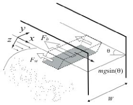
Knowing the rheology, it is then possible to write the momentum balance for a granular layer flowing on a heap. Let us consider a semi-infinite granular medium sandwiched between two smooth plates. We assume that the flow is uniform in the direction, the free surface making an angle with horizontal. In addition we neglect the variations of the velocity and the thickness in the direction. This simplification will be discussed in section 6.1. We can then write the force balance for a slice of material of length , thickness and width (figure 9).
Four forces apply on the elementary slice:
-
•
the gravity: , where .
-
•
the two lateral friction forces due to the side walls . Here two assumptions are made: first we assume that the beads slip against the side walls and we write the induce stress as a pure solid friction with a constant coefficient of friction . Measurement of glass beads sliding on glass walls gives . Second, the pressure is assumed to be isotropic. This last assumption seems to be verified in simulations ([Prochnow, Chevoir & Albertelli 2000]; [Silbert et al. 2001]).
-
•
the force that develops on the bottom face of the element due to the shear inside the material. According to our choice of the rheology (2), this force is , where .
The balance of the 3 forces leads to the following equation:
| (4) |
For a given inclination , the parameter and thus the shear rate are then obtained from equations (3) and (4) and then integrated to give the velocity profile. Before computing the velocity profile, a first remark can be made about the selection of the flow thickness. When going deeper in the pile – increasing –, the friction term due to the walls – the second term in (4) – increases. Consequently the force balance implies that decreases. However, the internal friction cannot be less than the critical value reached when goes to zero, i.e. when the material is not sheared (figure 8). As a consequence, there exists a critical depth below which the gravity, being screened by the lateral friction, is too weak to induce a shear in the material. The flow thickness is then given by the following relation:
| (5) |
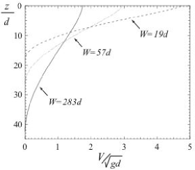
This linear relation between the flow thickness and the channel width has been previously obtained by other authors ([Roberts 1969]; [Savage 1979]; [Taberlet et al. 2003]). However, in our description where a local rheology is introduced, we can go further and analytically derive from (3) and (4) all the flow properties: the velocity profile and the variations with the flow rate of the inclination, of the surface velocity and of the thickness. The exact analytical expressions are given in appendix B. Examples of predicted velocity profiles are shown in figure 10. The flow is localized close to the free surface with a profile that looks like the ones experimentally observed.
Beyond the analytical results given in appendix B, interesting scaling laws arise from the expression of the dimensionless parameter . It is easy to show from equation (4) that the shear rate can be written as follows:
| (6) |
where the function is given in the appendix B. By successive integrations we then get the following scaling laws for the velocity and flow rate :
| (7) |
where
| (8) |
In all these expressions, the inclination plays the role of the control parameter. Since in our experiments we control the flow rate and not the inclination, it is convenient to rewrite the equations (5) and (7) choosing as a control parameter instead of . The scaling laws then write as follow:
| (9) |
where the functions , and can be linked to the functions , and (see appendix B). In terms of dimensional variables, the scaling laws are given by:
| (10) |
Let us underline that these scaling laws do not depend on the real shape of (3) but derive from the expression of the dimensionless number . Only the functions are related to the exact expression of .
Finally, one can show from the forces balance (4) and the shape of the friction coefficient (3) that steady uniform solutions are only possible for a finite range of surface inclinations given by . The lower limit corresponds to , i.e. the flow rate vanishes when . The upper limit corresponds to the maximal angle that can be balanced by the internal friction. Above this flow rate the flow accelerates along the pile. From appendix B (B), one can show that this maximal angle corresponds to a maximum flow rate for which steady flows are predicted:
| (11) |
5 Comparison with experimental measurements
5.1 Scaling laws
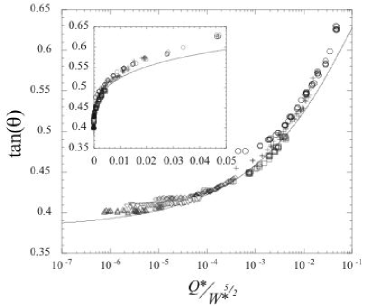
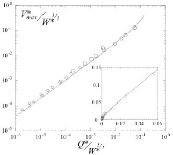
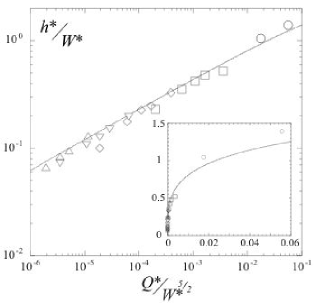
In order to check the validity of the theoretical model, we first compare all our experimental measurements carrying out for different widths and different flow rates with the predicted scaling laws (9). To this end, we have plotted in figures 11, 12 and 13 our measurements in terms of the three quantities , and as a function of , the scaling predicted by relations (9). The striking result is that, in the three cases, all the data obtained from different channel widths collapse on a single curve, showing that the predicted scalings correctly capture the influence of both the flow rate and the channel width. The collapse is perhaps less accurate in figure 11 for the inclination, where each set of data obtained for different seems to converge to a different angle for .
The second main result is that, not only collapse the experimental data, but they also quantitatively follow the theoretical predictions, as shown in figures 11, 12 and 13, where the solid lines correspond to predictions. The agreement between the model and the experimental data is quantitatively good, although one can notice that the predictions for the surface velocity are 15-20 below the measurements and those for the thickness are 10-15 above the measurements. Another quantitative test consists in studying the asymptotic behaviour at low flow rates. Power laws can be predicted by developing relations (9) for small flow rates as shown in the appendix C. One finds the following relations:
| (12) |
When comparing with the experimental measurements the agreement is good. The fit of our data gives for the surface velocity an exponent equal to to be compared with and for the thickness an exponent equal to to be compared to .
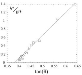
The last prediction that can be checked is the relation between the thickness and the angle (5) coming from the force balance. The model predicts a linear variation of the thickness with the tangent of the inclination. Figure 14 shows that our measurements are in good agreement with the theoretical results. The experimental data obtained for different widths collapse on a single straight line, with a slight departure from linearity observed at low flow rates. A good quantitative agreement is again obtained.
This analysis then shows that the characteristics of steady uniform flows on a heap are well predicted by our model based on the rate dependent friction law coupled with wall effects. It is important to keep in mind that in this analysis no parameter is fitted. The parameters of the rheological law have been chosen from the previous study by Forterre & Pouliquen (2003) who used the same granular material. The same rheology is therefore able to quantitatively describe flows on a rough inclined plane and surface flows on a heap.
In the next section we try to go further and discuss the domain of existence of steady uniform flows, by comparing the range of flow rates where they are observed with the prediction of the theory.
5.2 Minimum flow rate
In section 4.2 we have seen that the model predicts that steady uniform flows are possible for a range of flow rates going from zero, when the thickness vanishes and , to a maximum value when . We have not been able in our experiment to reach high enough flow rates to conclude about the existence or not of a maximum flow rate. However, our measurements clearly demonstrate the existence of a minimum flow rate for steady uniform flows, below which the flow is intermittent. This minimum flow rate depends on the channel width as shown in figure 4.
This transition between steady flows and intermittent flows is not predicted by the model. However, it is interesting to compare this situation with results about flow threshold obtained in the inclined plane configuration. It has been shown that, when a granular layer flows down a rough plane inclined at an angle without any side wall, no flow is possible if the layer thickness is less than a critical thickness ([Pouliquen ]; [Daerr 2001]; [Silbert, Landry & Grest 2003]). The existence of a critical thickness seems to be linked to the existence of correlations in the grain motions ([Ertas & Hasley 2002]; [GDR MiDi 2004]; [Pouliquen 2004]). Explaining the flow threshold of granular material is far beyond the scope of this study. However, it is interesting to wonder if a connection exists between the minimum thickness observed in the inclined plane configuration and the minimum flow rate we observe for flows on heap. When decreasing the flow rate on a heap, the flow thickness decreases. The critical flow rate can then be interpreted as a critical thickness. How does it compare with the minimum thickness observed on inclined plane?
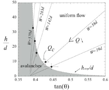
In order to answer this question, we consider a flow on a pile in a channel of width . For a given flow rate , the inclination of the free surface and the thickness are given in our model by equations (9). They are related by the linear relation (5) such that in the plane the system follows a straight line when varying . In figure 15, five of such lines are drawn corresponding to five different channel widths. In the model, each point of the lines corresponds a priori to a flow. However, experimentally this is not the case. Because there exists a critical flow rate below which the flow is intermittent, only the upper part of the lines in figure 15 can be reached. Our measurement of the critical flow rate then gives a critical thickness and a critical inclination , which are plotted in figure 15 for five widths. The striking results comes from the comparison between the positions of the points and the flow threshold observed on inclined plane. In figure 15, we have plotted as a dashed line the frontier between flow and no flow coming from the inclined plane experiments by Forterre & Pouliquen (2003) using the same glass beads. One observes that the transition points between steady and intermittent flows on a heap coincide with the frontier between flow and no flow in inclined plane. This result shows that the two a priori different conditions to get steady uniform flows in both configurations, heap flow and inclined plane flows, are quantitatively the same.
6 Discussion
6.1 Limits of the model
The theoretical model, which takes into account both the specificity of the granular rheology and the influence of lateral walls, gives good quantitative predictions for the steady uniform flows observed on heap. However, although the major features are captured, some discrepancies exist which give information about the limits of the approach.
The first limit is that we have written the forces balance assuming the flow to be uniform across the channel. This choice, which simplifies the theoretical description, does not allow to describe the velocity variations experimentally observed across the channel. If one wants to capture these three-dimensional effects, one has to take into account shear in the transverse direction. It is then necessary to write a generalization of the constitutive law (2) for fully three-dimensional deformations.
A second limit concerns the use of the local rheology written as a simple rate dependent friction law. As discussed in GDR MiDi (2004), this local approach is probably no longer valid close to the flow threshold or close to the boundaries. This limit is indeed observed in our case and gives rise to several discrepancies between the prediction and the measurements. The first one concerns the flow threshold. The local rheology is not able to predict the critical flow rate observed experimentally below which intermittent flows occur. We have been able to understand the existence of this minimum flow rate only by stipulating a priori that the flow cannot occur below a critical thickness, by analogy to the case of flows on inclined planes. The second discrepancy concerns the velocity profiles. The predicted profile presents a zero shear rate at the free surface and a static region with zero velocity deep inside the pile. Experimentally the velocity profile exhibits a non zero shear rate at the surface and an exponential tail deep in the pile ([GDR MiDi 2004]). One possible explanation for the limit of the local rheology is that close to the flow threshold or close to boundaries, non local phenomena have to be taken into account. Grain motions are correlated on lengths which become comparable to the flow thickness or to the distance to the boundaries ([Ertas & Hasley 2002]; [GDR MiDi 2004]; [Pouliquen 2004]). The precise understanding of this limit and the development of constitutive laws taken into account the non-local effects are still a challenge.
The last limit of our model lies in the description of the interaction of the flowing layer with the side walls. The stress that develops between the material and the glass wall is described in our model as a simple Coulomb friction. Whereas it is reasonable for slow flows, for fast flows collisions between particles and wall could occur and become predominant, leading to a rate dependent wall stress. This limitation could affect the maximum inclination predicted in our theory. According to our model, no steady uniform flow on a pile can occur above the angle . This value is typically between and degrees depending on the material used ([Forterre & Pouliquen 2003]). Recent experiments by Taberlet et al. (2003) report much higher slopes up to 60 degrees in narrow channels and at high flow rates. A plausible explanation for such high inclinations could be that the stress at the wall becomes collisional. Our model should then be modified to take into account a rate dependent wall friction.
6.2 Transition between flow on an inclined plane and flow on a pile
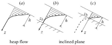
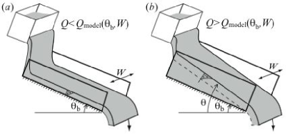
In the theory presented in section 4.2, the medium is considered as semi-infinite in order to model flows on a pile. However, flows of a finite layer corresponding to inclined plane experiments carried out in narrow channels can be described using the same approach. One just has to stipulate that the velocity should vanished at a given depth in order to reproduce the no slip condition on a rough surface. If the bottom plate is located deeper than the critical thickness predicted in the semi-infinite case, the bottom does not introduce any modification. The flow is made of a static layer close to the rough surface with a flowing region on top of it (figure 16b). However, when the bottom plate is close to the free surface, the model predicts that the whole granular layer is flowing. The velocity profile is therefore given by the upper part of the velocity profile for an infinite heap (figure 16c). This simple observation allows to better understand the formation of static piles observed in experiments on inclined planes in narrow channels. Savage (1979), Ancey (2001) and Taberlet et al. (2003) have shown that when the inclination is low or the flow rate is high, the material does not flow down to the bottom plate but a static pile develops. A transition is then observed between flow on a plane and flow on a pile. This can be understood as follow. In an inclined plane experiment the two control parameters are the inclination of the plane and the flow rate. For a given inclination, if the flow rate is less than the flow rate predicted in the case of semi infinite pile at this angle, we are in case of figure 16(c). The flow extends over the whole granular layer, the free surface being parallel to the bottom plane (figure 17a). However, when increasing the flow rate, the thickness increases and the friction with the wall becomes more and more important. Eventually, the only way for the system to overcome the side wall friction is to increase the free surface inclination at an angle higher than the bottom inclination (figure 17b). The formation of a static pile in confined inclined planes is thus controlled by the side walls. This explains why in very wide set-ups ([Pouliquen ]), or in molecular dynamic simulations using periodic boundary conditions ([Chevoir et al. 2001]; [Silbert, Landry & Grest 2003]), no static layer was ever observed, as soon as the inclination of the plate is above the repose angle of the material.
7 Conclusion
In this paper, steady uniform flows obtained when granular material is released at the top of a pile have been investigated. The influence of the side walls on these surface flows has been carefully studied, and a theoretical model has been proposed. From the experimental and theoretical analysis, two main conclusions emerge.
The first conclusion is that steady uniform flows on a pile are entirely controlled by side wall effects. The characteristics of flows in wide channels differ notably from the ones observed in narrow channels. For the same flow rate per unit of width, the flow is thicker and slower in a wide channel than in a narrow channel, thicknesses up to 70 particle diameters being observed. These observations contrast dramatically with the picture commonly accepted that the flowing zone is necessarily thin with a shear rate roughly constant. It means that precautions have to be taken when interpreting experimental results in narrow channels to get information about the intrinsic flow rheology.
The second result concerns the constitutive law for dense granular flows. Using the local rheology recently proposed in GDR MiDi (2004) and taking into account the friction due to the lateral walls, we have been able to reproduce the major characteristics of granular heap flows. In particular the localisation of the flow at the free surface is predicted, but appears to be a consequence of the wall friction and is not an intrinsic property of the rheology. Our analysis therefore dispels the difficulty raised in the article GDR Midi (2004), that flows on inclined planes and flows on a heap are not compatible when side wall effects are neglected. We have shown here that both configurations can actually be unified in the same framework choosing the rheology . The unification is not only qualitative but also quantitative. The flow thickness, the velocity and the free surface inclination measured for flow on a heap are predicted within 15 , when the friction law is calibrated based on measurements for flows on inclined planes. The comparison also extends to the flow threshold, which appears to be the same in both configurations once the critical flow rate observed in heap flows is interpreted in terms of a critical thickness. Of course, number of limits exists that has been identified and related to the fact that the proposed constitutive law is local. However, we believe that this approach represents a very serious candidate for a constitutive law for dense granular flows, as it is able to describe in the same framework three different configurations: Couette flows, inclined planes, and flows on a heap.
This study, which contrasts with previous results on surface flows, raises many questions. The first one concerns the generalisation of the constitutive law to three-dimensional deformations. We have seen that the approach proposed in this paper does not allow to describe the deformation observed in the transverse direction. What kind of constitutive law has to be written to capture this variation?
The second question concerns the role of the channel length. We have seen that in the steady uniform regime the flow thickness is controlled by the width of the channel. What would happen for very wide channels, when the width of the flow becomes comparable to the total length of the flow? Is the flow length in this case the new relevant length scale of the problem?
Another question concerns unsteady and non-uniform flows. What will happen for transient flows for example when avalanches are triggered on top of a pile? Do the side walls still play an important role in this case? To describe the complex dynamics of avalanches, several models have been proposed based on depth-averaged hydrodynamics equations ([Bouchaud et al. 1994]; [Boutreux, Raphaël & de Gennes 1998]; [Douady, Andreotti & Daerr 1999]; [Khakhar, Orpe & Ottino 2001]; [Aradian, Raphaël & de Gennes 2002]). What is the link between these approaches and the model presented here? Is it possible to get deeper insight on these models, now that we have more information about the internal rheology suitable for dense granular flows? These questions represent work for future investigations.
Finally, a last but fundamental issue concerns the physical origin of the constitutive law. Up to now the proposed rheology rests on an empirical ground. Attempts to link the observed macroscopic behaviour to the microscopic grain motion exist ([Mills,Loggia & Tixier 1999]; [Pouliquen, Forterre & Le Dizes 2001]; [Ertas & Hasley 2002]; [GDR MiDi 2004]) which are based on the idea that grains experience correlated or cluster-like motions. Recent experiments seem to support this idea ([Pouliquen 2004]; [Choi et al. 2004]), but the derivation of constitutive laws from microscopic bases remains an open challenge.
Acknowledgements.
The authors thank Bruno Andreotti for enlightening discussions and advices for the PIV method and Frédéric Ratouchniak for technical support.Appendix A Rheological law
In this appendix we show how the local constitutive law (3) can be obtained from the expression of the basal friction law obtained in experiments on inclined planes ([Pouliquen & Forterre 2002]; [Forterre & Pouliquen 2003]).
To this end we consider a granular layer of thickness flowing on a plane inclined at an angle . On one hand the experiments on steady uniform flows have shown that the bottom friction can be expressed in term of the thickness and the depth-averaged velocity as follow:
| (13) |
where , , and are constants. One the other hand, if one assumes that the material is described by the constitutive law with , the force balance in the bulk implies . This implies that the parameter is constant across the layer, independent of , depending only on the inclination of the plane. As a consequence, from the definition of , we obtain the velocity profile ([GDR MiDi 2004]):
| (14) |
From this equation we can compute the depth-averaged velocity:
| (15) |
From this result we can then rewrite the basal friction coefficient (13) in terms of the parameter as follow:
| (16) |
For consistency reason, the friction law is then given by:
| (17) |
with
| (18) |
In the constitutive law should be a constant, whereas it depends on through the term . However, this term does not vary much in the experimental range, such that one can think that it is missing in the expression (13) coming from the experimental data. Finally, from experimental measurements, Forterre and Pouliquen (2003) give , , , . Taking and an average value of for , we obtain . The parameters , and then quantitatively define the constitutive law.
Appendix B Analytical expressions for velocity profiles and for flow rate
Here we derive the expressions of the velocity profile and the flow rate as a function of the angle and of the depth . The local friction law (3) and the forces balance equation (4) give the following equation for the shear rate:
| (19) |
The minus sign before comes from the sign of the shear stress in our configuration. To simplify the expressions, we define:
| (20) |
which leads to:
| (21) |
Integrating the above equation with the boundary condition at , we find:
Integrating the previous equation from the bottom of the flowing layer () to the free surface yields:
Appendix C Asymptotic expressions at low flow rates
In this appendix we give the asymptotic relations between (11) for low flow rate, i.e. , and . Then (B) and (B) at the lower order give:
| (26) |
| (27) |
which can be rewritten as follow:
| (28) |
| (29) |
References
- [Ancey 2001] Ancey, C. 2001 Dry flows down an inclined channel: Experimental investigations on the frictional-collisional regimes. Phys. Rev. E 65, 011304.
- [Andreotti & Douady 2001] Andreotti, B. & Douady, S. 2001 Selection of velocity profile and flow depth in granular flows. Phys. Rev. E 63, 031305.
- [Aradian, Raphaël & de Gennes 2002] Aradian, A., Raphaël, E., de Gennes, P-G. 2002 Surface flows of granular materials: a short introduction to some recent models. C. R. Physique 3, 187-196.
- [Bonamy, Daviaud & Laurent 2002] Bonamy, D., Daviaud, F. & Laurent, L. 2002 Experimental study of granular surface flows via a fast camera: a continuous description. Phys. of Fluids 14, 1666-1673.
- [Bouchaud et al. 1994] Bouchaud, J. P., Cates, M., Prakash, J. R. & Edwards, S. F. 1994 A model for the dynamics of sandpile surfaces. J. Phys. France I 4, 1383–1410.
- [Boutreux, Raphaël & de Gennes 1998] Boutreux, T., Raphaël, E. & de Gennes, P. G. 1998 Surface flows of granular material: a modified picture for thick avalanches. Phys. Rev. E 58, 4692–4700.
- [Chevoir et al. 2001] Chevoir, F., Prochnow, M., Jenkins, J.T. & Mills, P. 2001 Dense granular flows down an inclined plane. in Y. Kishino, editor, Powders and Grains, pp 373-376, Tokyo, 2001. Lisse, Swets and Zeitlinger.
- [Chevoir et al. 2004] Chevoir, F., Da Cruz, F., Prochnow, M., Rognon, P. & Roux,J.-N. 2004 Dense granular flows : friction and Jamming. in Proceeding of the 17th ASCE Engineering Mechanics Conference, June 13-16, 2004, University of Delaware, Newark, DE.
- [Choi et al. 2004] Choi, J., Kudrolli, A., Rosales, R. R. & Bazant M. Z. 2004 Diffusion and Mixing in Gravity-Driven Dense Granular Flows. Phys. Rev. Lett. 92, 174301.
- [Courrech du Pont et al. 2003] Courrech du Pont, S., Gondret, P., Perrin, B. & Rabaud,M. 2003 Wall effects on granular heap stability. Europh. Let. 61 (4).
- [Da Cruz et al. 2004] Da Cruz, F., Chevoir, F., Roux, J.-N. & Iordanoff, I. 2004 Macroscopic friction of dry granular materials , in transient processes in tribology, proceedings of the 30th Leeds-Lyon Symposium on tribology (tribology and interface Engineering, 43, A. Lubrecht, G. Dalmaz (eds) (Elsevier, Amsterdam, 2004).
- [Daerr 2001] Daerr, A. 2001 Dynamical equilibrium of avalanches on a rough plane. Phys. Fluids 13, 2115-2124.
- [Douady, Andreotti & Daerr 1999] Douady, S., Andreotti, B. & Daerr, A. 1999 On granular surface flow equations. Eur. Phys. J. B 11, 131–142.
- [Dury et al. 1998] Dury, C. M., Ristow, G. H., Moss, J. L. & Nakagawa, M. 1998 Boundary effects on the angle of repose in rotating cylinders. Phys. Rev. E 57 (4).
- [Elperin & Vikhanski 1998] Elperin, T. & Vikhanski, A. 1998 Granular flow in a rotating cylindrical drum. Europhys. Lett. 42, 619-623.
- [Ertas & Hasley 2002] Ertas, D. & Halsey, T. C. 2002 Granular gravitational collapse and chute flow. Europhys. Lett., 60 (6), 931-937.
- [Félix, Falk 2002] Félix, G. 2002 PhD thesis, Institut National Polytechnique de Lorraine, Nancy, France, 2002.
- [Forterre & Pouliquen 2003] Forterre, Y. & Pouliquen, O. 2003 Long-surface-wave instability in dense granular flows. J. Fluid Mech. 486, 21-50.
- [GDR MiDi 2004] GDR MiDi 2004 On dense granular flows. Eur. Phys. J. E 14, 341-365.
- [Grasselli & Herrmann 1997] Grasselli, Y. & Herrmann, H. J. 1997 On the angles of dry granular heaps. Physica A, 246, 301-312.
- [Grasselli & Herrmann 1999] Grasselli, Y. & Herrmann, H. J. 1999 Shapes of heaps and silos. Euro. J. Phys. B, 10, 673-679.
- [Hill, Gioia & Tota 2003] Hill, K. M., Gioia, G. & Tota V. V. 2003 Structure and kinematics in dense free surface granular flow. Phys. Rev. Lett., 91, 064302.
- [Iordanoff & Khonsari 2004] Iordanoff, I. & Khonsari, M. M. 2004 Granular lubrication : toward an understanding between kinetic and uid regime. ASME J. of Tribology 126, 137-145.
- [Josserand, Lagrée & Lhuillier 2004] Josserand, C., Lagrée, P.-Y. & Lhuillier, D. 2004 Stationary shear flows of dense granular materials : a tentative continuum modelling Eur. Phys. J. E. 14, pp 127-135.
- [Khakhar et al. 2001] Khakhar D. V., Orpe, A. V., Andersen, P. & Ottino, J. M. 2001 Surface flow of granular materials: model and experiments in heap formation. J. Fluid Mech. 441, 255-264.
- [Khakhar, Orpe & Ottino 2001] Khakhar D. V., Orpe, A. V. & Ottino, J. M. 2001 Surface granular flows: two related examples. Adv. in Comp. Syst., 4, 407-417.
- [Komatsu et al. 2001] Komatsu, T. S., Inagaki, S., Nakagawa, N. & Nasumo, S. 2001 Creep motion in a granular pile exhibiting steady surface flow. Phys. Rev. Let. 86:1757-1760.
- [Lemieux & Durian 2000] Lemieux, P.-A. & Durian, D. J. 2000 From avalanches to fluid flow: A continuous picture of grain dynamics down a heap. Phys. Rev. Let. 85,4273-6.
- [Mills,Loggia & Tixier 1999] Mills, P., Loggia, D. & Tixier, M. 1999 Model for a stationary dense granular flow along an inclined wall. Europhys. Lett. 45, 733-738.
- [Pouliquen ] Pouliquen, O. Scaling laws in granular flows down rough inclined planes. Phys. Fluids 11, 542-548.
- [Pouliquen, Forterre & Le Dizes 2001] Pouliquen, O., Forterre, Y. & Le Dizes S. 2001 Slow dense granular flows as a self-induced process Adv. in Complex Syst., 4, 441-450.
- [Pouliquen & Forterre 2002] Pouliquen, O. & Forterre, Y. 2002 Friction law for dense granular flows: application to the motion of a mass down a rough inclined plane. J. Fluid Mech. 453, 133-151.
- [Pouliquen 2004] Pouliquen, O. 2004 Velocity correlations in dense granular flows. submitted to Phys. Rev. Lett..
- [Prochnow, Chevoir & Albertelli 2000] Prochnow, M., Chevoir, F. & Albertelli, M. 2000 Dense granular flows down a rough inclined plane. In Proceedings, XIIIth International Congress on Rheology, Cambridge, UK (2000)
- [Rajchenbach 1990] Rajchenbach, J. 1990 Flows in powder: from discrete avalanches to continuous regime. Phys. Rev. Let. 65 (18): 2221-2224.
- [Rajchenbach 2003] Rajchenbach, J. 2003 Dense, rapid flows of inelastic grains under gravity. Phys. Rev. Let. 90: 144302.
- [Roberts 1969] Roberts, A. W. 1969 An investigation of the gravity flow of noncohesive granular materials through discharge chutes. Trans. A.S.M.E., J. Engin. Indus. 91: 373-381.
- [Savage 1979] Savage, S. B. 1979 Gravity flow of cohesionless granular materials in chutes and channels. J. Fluid Mech. 92, 53-96.
- [Silbert, Landry & Grest 2003] Silbert, L. E., Landry, J. W. & Grest, G. S. 2003 Granular flow down a rough inclined plane: transition between thin and thick piles. Phys. Fluids 15, 1-10.
- [Silbert et al. 2001] Silbert,L. E., Ertas, D., Grest, G. S., Halsey, T. C., Levine, D. & Plimpton, S. J. 2001 Granular flow down an inclined plane: Bagnold scaling and rheology. Phys. Rev. E 64, 051302.
- [Taberlet et al. 2003] Taberlet, N., Richard, P., Valance, A., Delannay, R., Losert, W., Pasini, J.M. & Jenkins, J. T. 2003 Super stable granular heap in thin channel. Phys. Rev. Lett. 91, 264301.
- [Yamane et al. 1998] Yamane, K., Nakagawa, M., Altobelli, S. A., Tanaka, T. & Tsuji, Y. 1998 Steady Particulate Flows in a Horizontal Rotating Cylinder. Phys. of Fluids, 10:1419-1427.
- [Zhou et al. 2002] Zhou, Y.C., Xu, B.H., Yu, A.B., Zulli, P. 2002 An experimental and numerical study of the angle of repose of coarse spheres. Powder Tech. 125, 45-54.