Andreev Probe of Persistent Current States in Superconducting Quantum Circuits
Abstract
Using the extraordinary sensitivity of Andreev interferometers to the superconducting phase difference associated with currents, we measure the persistent current quantum states in superconducting loops interrupted by Josephson junctions. Straightforward electrical resistance measurements of the interferometers give continuous read-out of the states, allowing us to construct the energy spectrum of the quantum circuit. The probe is estimated to be more precise and faster than previous methods, and can measure the local phase difference in a wide range of superconducting circuits.
pacs:
03.67.Lx, 85.25.Cp , 85.25.DqSuperconducting circuits consisting of loops interrupted by Josephson junctions show persistent current states that are promising for implementation in a quantum computer mooij99 . Spectroscopy and coherent quantum dynamics of the circuits have been successfully investigated by determining the switching-to-voltage-state-probability of an attached superconducting quantum interference device (SQUID) chior03 ; however, a single switching measurement is low resolution and strongly disturbs both the circuit and the SQUID itself. This revives the fundamental problem of fast high resolution quantum measurements of the persistent current states. The conceptual and technological advance reported here is based on the fact that a persistent current in a quantum circuit is associated with the gradient of the superconducting phase of the macroscopic wavefunction describing the circuit. The problem of measuring the current reduces to a measurement of the corresponding phase difference across the Josephson junctions.
To measure with a minimum of disruption we use an Andreev interferometer pet94 ; naz96 . Our Andreev interferometers, shown in the scanning electron microscope images in Figs. 1a and b, are crossed normal () silver conductors - and -, with contacts to a pair of superconducting () aluminium wires at the points and . The interfaces play the role of mirrors reflecting electrons via an unusual mechanism first described by Andreev andreev64 . In Andreev reflection, an electron which is incident on the normal side of the interface evolves into a hole, which retraces the electron trajectory on the -side, and a Cooper pair is created on the -side. There is a fundamental relationship between the macroscopic phase of the superconductors and the microscopic phase of the quasiparticles spiv82 : the hole gains an extra phase equal to the macroscopic phase , and correspondingly the electron acquires an extra phase . This leads to phase-periodic oscillations in the resistance between the points and of the interferometer. It should be emphasized that the macroscopic phase is probed by quasiparticles with energies much less than the superconducting gap, so there is no “quasiparticle poisoning” of the superconductor.
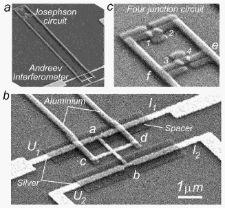
We investigate a Josephson quantum circuit with an attached Andreev interferometer, as shown in Figs. 1a and c. To probe the phase difference within the Josephson circuit, superconducting wires were connected to the points and , as shown in Fig. 1c. The four-terminal resistance was measured using the current (, ) and voltage (, ) probes shown in Fig. 1b. The oscillating part of the resistance depends on the superconducting phase difference between and , which can be described by pet98
| (1) |
where the amplitude is independent of . The phase difference can be written Lik86 as , where is the phase difference between the points and introduced by the lower branch of the Josephson loop. Due to a magnetic field applied perpendicular to the plane of the device, the total flux through the interferometer area (enclosed by ---) is , where is the external flux through which has an inductance . is the current circulating in the interferometer loop, and is the flux quantum .
Our Andreev probes were designed according to three
criteria:
I. To exclude parasitic potential differences
between the interfaces, we fabricate interferometer
structures that are symmetric crosses.
II. We ensure that the critical current induced in
the normal wires (and hence the current circulating in
the interferometer loop) is zero. Thus we exclude both the direct
influence of on the superconducting circuit, as well as
the back-action of the measuring current . According to
experimental basel99 ; shaik00 and theoretical
volkov95 ; wilhelm98 ; yip98 studies the influence of the
current through - on the superconductors connected at
- vanishes when the critical current is zero.
III. To suppress , but maintain the
sensitivity of the conductance to phase, the length must
satisfy the condition , where and are
the coherence length and the phase breaking length of the normal
metal, respectively; is the diffusion coefficient, and
is the normal metal phase breaking time. The critical
current is a thermodynamic property with contributions from
quasiparticles within of the Fermi energy, and decays
within the coherence length. In contrast, the phase coherent
conductance is a kinetic property with contributions within the
Thouless energy , and survives up to the
order of pet98 ; volkov96 ; golubov97 . In this
limit the Josephson circuit phase is given by
| (2) |
and does not depend on measurement details.
We have tested Andreev probes on three-junction mooij99 and four-junction Josephson circuits, and have found qualitatively similar behaviour for both circuits. Four-junction circuits allow a symmetric connection to the interferometer, which we believe minimizes the effect of noise currents in the interferometer loop on the quantum states. The devices were fabricated using three-layer electron beam lithography on silicon substrates covered with native oxide. The silver wires of the interferometer are 40 nm thick and 240 nm wide, and the aluminium superconducting wires are 35 nm thick and 360 nm wide. The Josephson circuits are also aluminium, interrupted by Al2O3 Josephson junctions (Figs. 1 a,c). The spacer was a 30 nm thick Al2O3 film (Fig. 1b). Resistances were measured using standard low frequency techniques at temperatures between 0.02- 1.2 K.
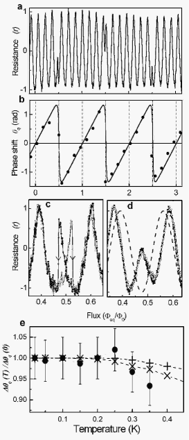
Figure 2a shows the normalized resistance of an interferometer with m, measured as a function of normalized magnetic flux , where is the external flux through the Josephson junction loop area m2. Using a test structure the circulating current in the interferometer loop was measured to be zero, in agreement with a coherence length in silver of m (estimated from cm2/s, which was obtained from resistivity measurements). Interference oscillations are measured with a period close to through the interferometer area m2. The amplitude depends on the resistance of the interfaces, reaching values up to pet94 . In this particular device and . The measurement current was A, and the magnetic flux induced by this current was negligible. Figure 2a shows there are abrupt phase shifts when the flux corresponds to an odd number of half flux quanta, , where is an integer. The dependence of the phase on magnetic flux is shown in Fig. 2b; the sawtooth structure results from a build-up of persistent current in the Josephson loop, followed by a transition between states of different circulation.
The shape of the transition at depends on parameters of the Josephson circuit. Figure 2c shows transitions in a circuit with inductance nH, and a high critical current, A. There is hysteresis associated with the transitions from clockwise to anticlockwise persistent current states; this is the classical regime where the Josephson energy (and the potential barrier between the persistent current quantum states) is so high that there is no quantum tunnelling at . Figure 2d shows a close-up of the oscillations in Fig. 2a, measured in a Josephson circuit with a lower critical current, A; there is a smooth switch from one state to another, with no evidence of hysteresis. Also shown in Fig. 2d is a dashed line that corresponds to , which crosses the measured curve at , the flux at which .
We have measured the influence of the measuring current on the phase . To within the accuracy of our measurements (less than 5%), the amplitude of is unaffected by currents up to A (corresponding to 25 V across -). High currents may also induce thermal effects; however, as shown in Fig. 2e the amplitude of is constant over a wide range of temperatures.
Our phase measurements allow us to investigate the energy spectrum of the Josephson circuit. From the equation , the phase difference across the Josephson junction is related to the persistent current in the Josephson loop; is itself related to the energy of the Josephson loop through the derivative . Therefore, the equation
| (3) |
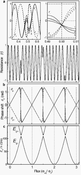
shows that measurements allow the determination of the energy spectrum . To demonstrate the technique, we use a generic form for the spectrum
| (4) |
where is the energy gap at between the excited () and ground () states. For energies far away from the degeneracy point , we take the junction charging energy ( is the junction capacitance) to be much less than the Josephson energy (test structures show that , with GHz and GHz). Then can be modelled with the two-junction energy , where . To fit our measurements (Fig. 2) of the ground state there is only one free parameter ; we find that produces the best fit to and over a wide range of flux, as well as generating the energy spectrum in Fig. 3c. The model can also describe the temperature dependence of the amplitude of shown in Fig. 2e; the reduction of due to thermal fluctuations is given by , and the resulting calculated amplitude of is shown as dashed lines in Fig. 2e for () and ().
In anticipation of measurements of the excited states, we use the spectrum to calculate, see insets of Fig. 3a, the resistance of the ground state and excited state . When the circuit is irradiated with frequency , the measured voltage is expected to oscillate at the Rabi frequency with an amplitude .
The probe has an operating range from DC to an upper frequency, , which is limited by the quasiparticle’s finite time-of-flight between the N/S interfaces. For our probe GHz. The wide frequency response allows measurements in both the continuous “Rabi spectroscopy” regime ilichev03 and the pulse regime chior03 ; lup04 . Note, the Andreev probe measures local phase differences, enabling the direct determination of quantum entanglement between different elements of complicated Josephson circuits, which could be unattainable with previous methods ilichev03 ; lup04 . An increase in the operation speed by orders of magnitude can be achieved using ballistic Andreev interferometers made using a high mobility two-dimensional electron gas (2DEG), which will also allow gate-controlled Andreev probes. Additionally, probes can be fabricated to be impedance matched to standard 50 or 75 high frequency setups.
From our measurements we estimate the efficiency of the Andreev probe compared to other methods. The signal-to-noise ratio () for continuous measurements over a frequency range is , where is the spectral density of the voltage noise. With , , A, kHz, and with the noise temperature of the cold amplifier K used in ilichev03 we obtain for the thermal noise, which is two orders of magnitude larger than previously reported ilichev03 .
For the pulse technique an important parameter is the discrimination time , which is the time required to obtain enough information to infer the quantum state. For reflection measurements, the “single shot” measurement time is calculated to be , where is the reflected signal, , where and . Substituting the cold amplifier noise temperature K used in lup04 , , , A, we estimate s for the thermal noise - this is more than an order of magnitude shorter than reported in lup04 . can be further improved using lower noise cryogenic amplifiers. Measurements of the excited states will reveal the actual decoherence mechanisms. In the mesoscopic interferometer the thermal noise current can be minimized by reducing the number of conducting channels in the length .
In summary, simple resistance measurements of an Andreev interferometer provide direct read-out of the local superconducting phase difference in quantum circuits; within the accuracy of existing theory there is negligible back-action on the quantum circuit. From the phase , the energy spectrum can be constructed. The probe is expected to be more precise and faster than previous methods ilichev03 ; lup04 , and can measure the local phase difference in a wide range of superconducting circuits. The 2DEG-based Andreev probe can be made gate-controlled. Our probe will allow us to address fundamental aspects of quantum measurements. As the operator of the average phase commutes with the two-state Hamiltonian, measuring the average phase may enable realization of “quantum non-demolition” (QND) measurements braginsky96 , possessing important features such as an accuracy that exceeds quantum limits averin02 .
We thank Yu. V. Nazarov, D. V. Averin, P. Delsing, M. Lea, A. F. Volkov, D. Esteve, D. Vion, H. Pothier, A. Zagoskin, and A. M. van den Brink for valuable discussions. This work was supported by the Engineering and Physical Sciences Research Council (UK).
References
- (1) J. E. Mooij et al., Science 285, 1036 (1999).
- (2) I. Chiorescu et al., Science 299, 1869 (2003).
- (3) V. T. Petrashov, V. N. Antonov, P. Delsing, and T. Claeson, Pis’ma Zh. Eksp. Teor. Fiz. 60, 589 (1994), [JETP Lett. 60, 606 (1994)]; Phys. Rev. Lett. 74, 5268 (1995).
- (4) Y. V. Nazarov and T. H. Stoof, Phys. Rev. Lett. 76, 823 (1996).
- (5) A. F. Andreev, Zh. Eksp. Teor. Fiz. 46, 1823 (1964), [Sov. Phys. JETP. 19, 1228 (1964)].
- (6) B. Z. Spivak and D. E. Khmel’nitskii, Pis’ma Zh. Eksp. Teor. Fiz. 35, 334 (1982), [JETP Lett. 35, 412 (1982)].
- (7) V. T. Petrashov et al., Phys. Rev. B 58, 15088 (1998).
- (8) K. K. Likharev, Dynamics of Josephson Junctions and Circuits (Gordon & Breach, New York, 1986).
- (9) J. J. A. Baselmans et al., Nature 397, 43 (1999).
- (10) R. Shaikhaidarov et al., Phys. Rev. B 62, 14649 (2000).
- (11) A. F. Volkov, Phys. Rev. Lett. 74, 4730 (1995).
- (12) F. K. Wilhelm et al., Phys. Rev. Lett. 81, 1682 (1998).
- (13) S. K. Yip, Phys. Rev. B 58, 5803 (1998).
- (14) A. F. Volkov and H. Takayanagi, Phys. Rev. Lett. 76, 4026 (1996).
- (15) A. A. Golubov et al., Phys. Rev. B 55, 1123 (1997).
- (16) E. Il’ichev et al., Phys. Rev. Lett. 91, 097906 (2003).
- (17) A. Lupaşcu et al., Phys. Rev. Lett. 93, 177006 (2004).
- (18) V. B. Braginsky and F. Y. Khalili, Rev. Mod. Phys. 68, 1 (1996).
- (19) D. V. Averin, Phys. Rev. Lett. 88, 207901 (2002).