Spin resolved Hall effect driven by spin-orbit coupling
Abstract
Spin and electric Hall currents are calculated numerically in a two-dimensional mesoscopic system with Rashba and Dresselhaus spin-orbit coupling by means of the Landauer-Büttiker formalism. It is found that both electric and spin Hall currents circulate when two spin-orbit couplings coexist, while the electric Hall conductance vanishes if either one is absent. The electric and spin Hall conductances are suppressed in strong disorder, but survive in weak disorder. Physically it can be understood that the spinomotive transverse ”force” generated by spin-orbit coupling is responsible for the formation of the spin Hall current and the lack of transverse reflection symmetry is the origin of the electric Hall current.
pacs:
72.25.-b, 75.47.-mWhen a metallic sample is subjected to a perpendicular external magnetic field, the Lorentz force acting on the charge carriers gives rise to a transverse voltage between two edges of the sample, this is well known as the ordinary Hall effect. Actually the Hall effect family has numbers of important members. The anomalous Hall effect may occur even in the absence of an external magnetic field in a ferromagnetic metal with spin-orbit coupling.Chien79 ; Karplus54 ; Smit55 ; Berger70 ; Onoda02JPSJ ; Jungwirth02PRL ; Onoda03prl ; Fang03 In the past few years it has been recognized that the spin-orbit coupling may provide an efficient way to manipulate a spin resolved current in metals and semiconductors.Dyakonov71 ; Hirsch99prl ; Zhang00prl ; Hu03prb ; Murakami03Science ; Sinova04prl ; Shen04prl In a two dimensional electron gas (2DEG) lacking bulk and structure inversion symmetries, the effective Hamiltonian is given by
| (1) |
where the second term is the Rashba spin-orbit coupling and the third one is the Dresselhaus spin-orbit coupling. () are the Pauli matrices and the coupling parameters and have the dimension of velocity. Using the Heisenberg equation of motion the second derivative of the position operator gives
| (2) |
Compared with the Lorentz force brought by the magnetic field upon a charged particle, the spin-orbit coupling produces a spinomotive transverse ”force” on a moving electron. It has no classical counterpart as the coefficient is divided by , but it reflects the tendency of spin asymmetric scattering of a moving electron subject to the spin-orbit coupling. When charge carriers are driven by an external electric field, this ”force” tends to form a transverse spin current.
In this paper we calculate the spin and electric Hall conductances in a 2DEG mesoscopic system with Rashba and Dresselhaus coupling by using the Landauer-Büttiker formula and the Green’s function technique. It is found that both electric and spin Hall currents circulate while these two types of spin-orbit coupling coexist, but the electric Hall current disappears when either one is absent. The spin and electric Hall conductances are suppressed in strong disorder, but survive in weak disorder. The numerical results are in good agreement with the symmetry analysis of the system.
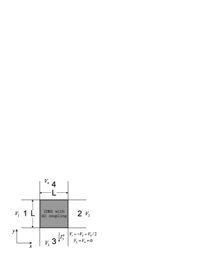
We consider a cross-shape device with four semi-infinite metallic leads as shown in Fig. 1. The scattering region (shadowed part in Fig. 1) is described by the effective Hamiltonian in Eq.(1), and when it is treated as an lattice with the tight-binding approximation, the model Hamiltonian reads,
| (3) | |||||
where and are the dimensionless parameters for Rashba and Dresselhaus coupling strength in the unit of , respectively, and the local spin current operator is defined as Shen97pla
| (4) |
where stands for the unit vector along axes of the lattice and stands for the direction of spin polarization.note-unit
The calculation of electric and spin currents is based on the Landauer-Büttiker formalism.Buttiker86prl ; Datta95 Assume to be the spin-resolved transmission probability of electrons transmitted from spin channel of lead to spin channel of lead , and to be the electric voltage in lead , then respectively the outgoing electric current and spin current polarized along direction in lead are
| (5) | |||||
| (6) |
The transmission probability coefficients can be calculated by using the Green’s function technique, Tr And the retarded and advanced Green functions are given by , where is the electron energy and is the model Hamiltonian in the shadowed region in Fig.1. The retarded and advanced self energy terms introduced by the semi-infinite lead , and where is the transverse mode wave function at site in lead connected to the scattering region. It should be noted that in Eq.(6) may stand for an arbitrary direction of spin polarization, and this is done by incorporating a transformation in the definition of , that is, and is the rotation matrix to transform the eigenstates of to those of ( is a unit vector).note The Landauer-Büttiker formalism has been applied extensively to study the spin transport in mesoscopic systems numerically.Pareek04prl ; Hankiewicz04prb ; Sheng05prl ; Nikolic04xxx
In this paper we consider an initial electric current driven through leads 1 and 2, by setting the bias voltage and The currents in leads 3 and 4 are perpendicular to the current through leads 1 and 2. Thus the electric and spin Hall conductances are defined as
| (7) | |||||
| (8) |
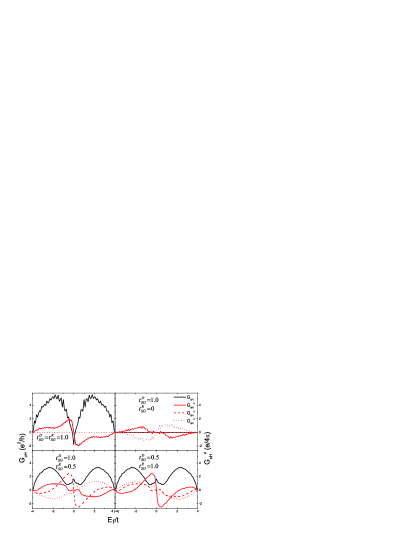
respectively, where the spin current has three components, Electric and spin Hall conductances are evaluated as functions of the Fermi energy for different ratios of Rashba and Dresselhaus coupling strength in Fig. 2. Generally speaking, the electric Hall conductance is symmetric about the Fermi energy while the spin Hall conductance is antisymmetric such that the spin Hall conductance vanishes at the band center, . This is consistent with the symmetry analysis for the tight binding Hamiltonian.Sheng05prl In the case of the pure Rashba or Dresselhaus coupling, the electric Hall conductance disappears, but the spin Hall conductance still exists. In the two cases of and and of and the electric Hall conductances are equal. However the spin Hall conductances differ by a minus sign, with and swapped, and the former is consistent with Shen and Sinitsyn et al’s works for free 2DEG systems.Shen04prb ; Sinitsyn04prb A special case is at the symmetric point of . The spin Hall conductance , while and are equal and non-zero, which means the current is polarized within the x-y plane. In this case the operator commutes with the total Hamiltonian, and actually there is no spin flip in the scattering region.Schliemann03prl On the other hand the longitudinal electric and spin conductances are also non-zero. The longitudinal conductances are about one order larger than the Hall conductances in magnitude, i.e., And the electric conductance is also symmetric with respect to the Fermi energy, just like the electric Hall conductance, while the longitudinal spin current is antisymmetric. According to the symmetry properties of such a system,Shen04prb under the transformation: and and , correspondingly and while the electric Hall conductance remains unchanged. At the symmetric point, it yields that and Our numerical results obviously agree with this symmetry analysis.
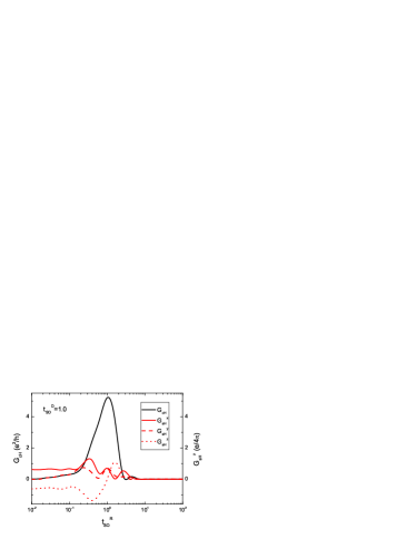
The Hall conductances as functions of the Rashba coupling strength are also evaluated, with specific Dresselhaus coupling strength and electron Fermi energy as shown in Fig. 3. It indicates clearly that the electric Hall conductance increases with increasing the Rashba couple strength, and reaches its maximal value at . Then it turns to decrease when and approaches to zero for a large Rashba coupling strength. The figure shows that and at as expected by the symmetry analysis. For a large spin-orbit coupling both electric and spin Hall conductance approaches to zero because the spin-orbit coupling in the scattering region forms a large potential barrier and the incident electrons will be completely reflected. Unlike bulk systemsShen04prb ; Sinitsyn04prb where the spin Hall conductance in the clean limit has a universal value and the sign is given by the relative ratio of two coupling strength in Eq.(1), Fig. 3 shows that the value of spin Hall conductance varies with the relative ratio as well as the sign, but the change of sign is compatible with the bulk systems case. And this result is also compatible with the previous numerical work in the case of pure Rashba coupling.Sheng05prl ; Nikolic04xxx ; Nomura05prb
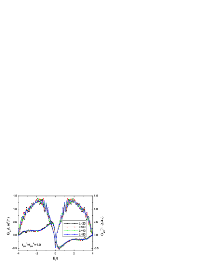
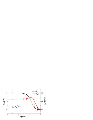
To see the finite size effect we calculate the electric and spin Hall conductances for , , , and . and as functions of are plotted in Fig. 4. We notice that these curves for different sizes fit a single one very well. Thus we conclude that both electric and spin Hall conductance are proportional to the size of the sample. In other words, in our calculation the electric and spin Hall currents are determined by both the number of the incident channels and that of the outgoing channels. Thus the Hall currents induced by a specified longitudinal electric field are not proportional to the size linearly, but to .
The disorder effect is an interesting issue in the spin Hall effect in 2DEG. It is still greatly controversial whether the spin Hall effect may survive when the impurity scattering is taken into account.Inoue04prb ; Mishchenko04prl ; Rashba04prb We consider the disorder effect by including the disorder potential term in Eq.(3) where are randomly distributed between . Selectively the electric and spin Hall conductances, and for two couplings with equal strength are plotted in Fig. 5. is exactly equal to zero according to the symmetry. It shows that both electric and spin Hall conductances can survive in weak disorder, but be suppressed in strong disorder. We also did calculation for several other cases, and obtained similar results. The case of pure Dresselhaus coupling is in agreement with Sheng et al’s work for pure Rashba coupling.Sheng05prl
Physically the spin Hall conductance can be well understood from the spinomotive transverse ”force” caused by the spin-orbit coupling in Eq.(2). The electric field drives electrons moving along the field such that the electrons with spin-up or -down experience opposite transverse ”force” and thus a non-zero spin current is induced perpendicular to the field. The relative ratio of the two coupling strength determines the direction of the spin Hall current as the spinomotive force changes its sign around and vanishes at the point. All calculated results are consistent with this. However, the spinomotive force is not a direct origin of the non-zero , since arises only when two couplings are present simultaneously. From the symmetry properties of the system we notice that the Hamiltonian with pure Rashba coupling is invariant under the transformation: and . Similarly the Hamiltonian with pure Dresselhaus coupling is invariant under the transformation: and . This is why the electric Hall current vanishes in these two cases, while the spin Hall current circulates because there is no symmetry constraint on it as both and change their signs under such transformation. On the other hand, the Hamiltonian with both Rashba and Dresselhaus couplings does not possess the reflection symmetry of . Therefore the coexistence of both couplings breaks the reflection symmetry of the system, which makes the electric current not parallel to the electric field such that it gives rise to a nonvanishing Hall conductance . This unconventional Hall conductance may be related to some discussions in terms of the anomalous Hall effect due to parity anomaly and additional band crossingOnoda02JPSJ . Moreover, since the diagonal spin conductance is non-zero in this caseSinitsyn04prb , the diagonal spin current along leads 1 and 2 might generate a charge Hall current via the reciprocal spin Hall effect.Zhang05xxx
In conclusion, we studied the electric Hall conductance as well as the spin Hall conductance for a finite-size system with four leads. Both electric and spin Hall conductances are non-zero when both Rashba and Dresselhaus coupling are present, thus the current is actually spin polarized. Unlike the anomalous Hall effect, the present electric Hall current is driven by the spin-orbit coupling, not by the exchange coupling with the magnetic impurities.Culcer03prb This effect also differs from the one resulted from a spin polarized current via the Rashba coupling.Bulgakov99prl Though the incident current is not spin polarized, the Hall current is polarized in our case.
The authors would like to thank L. Sheng and D. N. Sheng for helpful discussions. This work was supported by the Research Grant Council of Hong Kong (SQS), and by the National Science Foundation of China under Grant No.: 10474022 (LBH).
References
- (1) C. L. Chien and C. R. Westgate (eds.), The Hall Effect and its Applications (Plenum, New York, 1980)
- (2) R. Karplus and J. M. Luttinger, Phys. Rev. 95, 1154 (1954)
- (3) J. Smit, Physica (Amsterdam) 21, 887 (1955)
- (4) L. Berger, Phys. Rev. B 2, 4559 (1970)
- (5) M. Onoda and N. Nagaosa, J. Phys. Sco. Jpn. 71, 19 (2002)
- (6) T. Jungwirth, Q. Niu, and A. H. MacDonald, Phys. Rev. Lett. 88, 207208 (2002)
- (7) M. Onoda and N. Nagaosa, Phys. Rev. Lett. 90, 206601 (2003)
- (8) Z. Fang, N. Nagaosa, K. S. Takahashi, A. Asamitsu, R. Mathieu, T. Ogasawara, H. Yamada, M. Kawasaki, Y. Tokura, and K. Terakura, Science 302, 92 (2003)
- (9) M. I. D’yakonov and V. I. Perel, JETP Lett. 13, 467 (1971)
- (10) J. E. Hirsch, Phys. Rev. Lett. 83, 1834 (1999)
- (11) S. Zhang, Phys. Rev. Lett. 85, 393 (2000)
- (12) L. Hu, J. Gao, and S. Q. Shen, Phys. Rev. B 68, 115302 (2003); ibid. 68, 153303 (2003)
- (13) S. Murakami, N. Nagaosa, and S. C. Zhang, Science 301, 1348 (2003)
- (14) J. Sinova, D. Culcer, Q. Niu, N. A. Sinitsyn, T. Jungwirth, and A. H. MacDonald, Phys. Rev. Lett. 92, 126603 (2004)
- (15) S. Q. Shen, M. Ma, X. C. Xie, and F. C. Zhang, Phys. Rev. Lett. 92, 256603 (2004); S. Q. Shen, Y. J. Bao, M. Ma, X. C. Xie, and F. C. Zhang, cond-mat/0410169.
- (16) S. Q. Shen, Phys. Lett. A 235, 403 (1997)
- (17) The unit of the spin current operator is ( is the lattice space), and here we take .
- (18) M. Buttiker, Phys. Rev. Lett. 57, 1761 (1986)
- (19) S. Datta, Electronic Transport in Mesoscopic Systems (Cambridge University Press, Cambridge, 1995)
- (20) We take as up () and as down () as the indices of the rotation matrix
- (21) T. P. Pareek, Phys. Rev. Lett. 92, 076601 (2004)
- (22) E. M. Hankiewicz, L. W. Molenkamp, T. Jungwirth, and J. Sinova, Phys. Rev. B 70, 241301 (2004)
- (23) L. Sheng, D. S. Sheng, and C. S. Ting, Phys. Rev. Lett. 94, 016602 (2005)
- (24) B. K. Nikolic, L. P. Zarbo, and S. Souma, cond-mat/0408693
- (25) S. Q. Shen, Phys. Rev. B. 70, 081311 (2004)
- (26) N. A. Sinitsyn, E. M. Hankiewicz, W. Teizer, and J. Sinova, Phys. Rev. B 70, 081312 (2004)
- (27) J. Schliemann, J. C. Egues, and D. Loss, Phys. Rev. Lett. 90, 146801 (2003)
- (28) K. Nomura, J. Sinova, T. Jungwirth, Q. Niu, and A. H. MacDonald, Phys. Rev. B 71, 041304 (2005)
- (29) J. Inoue, G. E. W. Bauer, and L. W. Molenkamp, Phys. Rev. B 70, 041303 (2004)
- (30) E. G. Mishchenko, A. V. Shytov, and B. I. Halperin, Phys. Rev. Lett. 93, 226602 (2004)
- (31) E. I. Rashba, Phys. Rev. B 70, 201309 (2004)
- (32) P. Zhang, J. Shi, D. Xiao, and Q. Niu, cond-mat/0503505
- (33) D. Culcer, A. MacDonald, and Q. Niu, Phys. Rev. B 68, 045327 (2003)
- (34) E. N. Bulgakov, K. N. Pichugin, A. F. Sadreev, P. Streda, and P. Seba, Phys. Rev. Lett. 83, 376 (1999)