Laser-controlled local magnetic field with semiconductor quantum rings
Abstract
We analize theoretically the dynamics of electrons localized in a semiconductor quantum ring under a train of phase-locked infrared laser pulses. The pulse sequence is designed to control the total angular momentum of the electrons. The quantum ring can be put in states characterized by strong currents. The local magnetic field created by these currents can be used for a selective quantum control of single spins in semiconductor systems.
pacs:
73.23.Ra, 78.67.-nThe quantum control by trains of phase-locked laser pulses is a powerful and intuitive technique that has been applied to many atomic and molecular systems. It has been successfully employed in controlling the angular momentum of Rydberg electrons and molecular wavepackets verlet02 , and it was the key technique in the creation of Schrödiger cat’s states in Rydberg atoms noel96 . Semiconductor quantum dots and rings are artificial atoms with energy levels that can be engineered, and the realization of optical control in these systems is particularly appealing for quantum device applications.
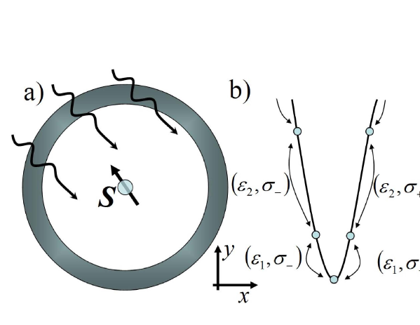
In this paper we propose a scheme involving phase-locked infrared pulses to control the total angular momentum of N electrons in a quantum ring. This implies that a strong current can be generated in the ring. The latter can be exploited to generate and control a local magnetic field in spin-based quantum computers kane98 ; privman98 . A possible application of the radiation-induced currents to single spin control is shown in Fig. 1(a). A spin, provided e.g. by a magnetic impurity, is embedded at the center or on top of a narrow quantum ring and can be locally controlled by the magnetic field due to the current in the ring. A scheme that uses arrays of parallel wires to create localized magnetic fields has been recently proposed Lidar . The significant advantage of our laser-controlled approach is that it does not require external leads: the magnetic field is controlled by laser pulses. The peculiar orbital properties of the many-body eigenstates in a quantum ring and Pauli blocking effects make this scheme robust against the relaxation of the current by phonon and photon emission.
Small semiconductor nanorings can be made by the same self-assembly methods used for the fabrication of quantum dots. Persistent currents due to the Aharonov-Bohm flux have been observed in these quantum structures in the presence of an external magnetic flux along the ring axis lorke00 . Currently, there is great theoretical interest in persistent currents VRWZ98 ; Qian ; Serega ; Manolescu ; PCwithSO ; Peeters ; PCquantc ; ulloa97 . In particular, it is believed that they can be generated, besides using an external magnetic flux, also by the interplay of spin-orbit interaction and hyperfine coupling VRWZ98 ; Qian . We propose here that circularly polarized radiation can create currents in a quantum ring without an external magnetic flux. The circular polarization of the light propagating along the axis of the ring breakes the clockwise-anticlockwise symmetry of the many-electron wavefunction. In the case of a cw excitation these currents are persistent currents: they are associated to the ground state of the ring dressed by the external laser field. Pulsed lasers can however produce stronger currents in a shorter time, which is more interesting for our purpose. We will discuss the cw case elsewhere. Notice that linearly polarized excitation will not induce a current but can affect the current induced by an external magnetic flux Manolescu .
We start from , the exact N-electron ground state of a narrow ring Hamiltonian
| (1) |
is the ring radius, is the electron effective mass and are the axial coordinates of the electrons. is the electron-electron Coulomb interaction. The operator commutes with the and . We want to design a multi-pulse control Hamiltonian of the form
| (2) |
where is the total dipole moment of the electrons and is the electric field of the -th pulse. The target states in our scheme are written as
| (3) |
with integer, and are exact eigenstates of the Hamiltonian in Eq. (1) with energy and with . These states are called compact states and they can be seen as rigid rotational modes of the many-body electron system as a whole. The wave functions and are linked by a rotating wave transformation and their Coulomb correlation properties are identical. Every time a polarized photon is absorbed or emitted the total increases or decreases by one, while the opposite is valid for .
Let us consider first the dynamics of a single electron confined in the ring neglecting relaxation processes. The energy, wave function, and current of an electron in the -th level are given by
| (4) |
The time-dependent electric field generates transitions between the levels . We write the electric field associated to the -th pulse as which accounts for arbitrary polarization. corresponds to polarization and to polarization. Matrix elements for dipole transitions are non-zero only between nearest single-particle states , where denotes radiation. By writing the electron wave function in the form , where gives the probability to find the electron in the state , we get, for polarization, the equation of motion

| (5) |
where is the Rabi energy. The unitary transformation allows us to eliminate the exponential factors in Eq. (5)
| (6) |
From Eq. (6) it follows that resonant transitions between two levels occur when , where . Notice that for any and , meaning that radiation can only excite resonant transitions between levels with . For polarization, the dynamics of is described by Eq. (6) with replaced by . It can be shown that radiation can only excite resonanant transitions between levels with . The selection rules for single electron transitions are shown in Fig. 1(b).
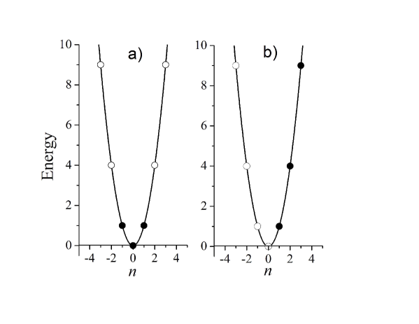
Consider now -electron states of spinless and non-interacting electrons. Starting from a ground state, like the one in Fig. 2(a) for =3, and using a sequence of pulses, our goal is to put the electrons in a compact state that is characterized by a strong current like e.g. the one in Fig. 2(b). If in the ground state the levels , …, are populated, in the final compact state the levels , …, are populated, i.e. electrons are moved from the states with negative angular momentum to the states with positive angular momentum. This is accomplished using a sequence of pulses with frequency and polarization , , …, , , …, , , …, where . Notice that (i) each pulse increases by one by stimulated absorption of a or stimulated emission of a photon, and (ii) at each step in the sequence the energy of the optical transition is the smallest allowed by the many particle energy configuration on condition that increases by one. This implies that in our path toward the target compact states we follow the lowest energy states with fixed total (yrast line of excitations). From an operative standpoint, the polarization and the energy of the pulse in the sequence can be directly determined by spectroscopic measurements on the system. The energy of the photon to be used corresponds to where is the lowest -polarized peak in absorption, and is the lowest -polarized peak in emission/gain. In the ideal case the final current is
| (7) |
which is times stronger than the typical amplitude of the persistent current oscillations induced by the Aharonov-Bohm flux.
The general idea of optical transitions with the smallest exchange of energy can be generalized to include the spin of the electrons. Notice that in the absence of spin-orbit coupling the total spin of the electrons is conserved in the transitions. We have found that if a spin-orbit coupling of the Rashba form is present, this control scheme can create spin-polarized currents in the ring pershinfuture . Many-body calculations done using the configuration interaction method viefers04 show that the yrast line of excitations is always well separated from high excited states in small rings. Therefore in that case our general prescription for the pulse sequence to target compact states will not be affected by the presence of Coulomb interaction. The total exchange of energy at the end of the pulse sequence does not depend on the Coulomb interaction. The electromagnetic field provides only the kinetic energy necessary to a rigid rotation of all the electrons, since the potential energy of all compact states is the same of the one in the ground state.
Off-resonant population transfer and relaxation will affect our control scheme. We give a full description of the electron dynamics in the ring using a density matrix formalism. We include all non-resonant transitions without rotation wave approximation in the simulation. The equation of motion of the density matrix is given by where the relaxation superoperator has the form with Lindblad operators describing decoherence and relaxation processes lindblad76 .
In order to demonstrate our approach, we solve the Liouville equation numerically assuming that 3 electrons are in the ring. Limiting our consideration to possible single-particle states (shown in Fig. 2), the ground state of the system can be represented as , where the indicates an occupied level and an empty level. The level is identified by a bold-face index. There are 35 possible states that can be obtained with different occupations of 7 levels by 3 electrons. We start from the configuration where only the ground state is populated, assuming that . The optical control is realized with pulses of rectangular shape. We select the pulse duration to obtain pulses as .
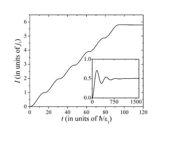
Fig. 3 shows the result of our calculations. The applied pulse sequence generates almost perfect transitions between the states. The diagonal matrix elements in Fig. 3 correspond to the states indicated in the inset. We note that off-resonance transitions and relaxation result in the decrease of the maximum of population inversion at long times. The small fast oscillations of the diagonal density matrix elements (clearly resolved, for example, for at ) are due to off-resonanant transitions. The current in the ring is calculated as , where is the quantum mechanical current operator, and is shown in Fig. 4. Its saturation value at is close to the ideal value predicted by Eq. (7). We show for comparison in the inset of Fig. 4 the current obtained with a cw excitation. The initial oscillation is due to the Rabi oscillation between two states, but the equilibrium value gives a finite value for the current. The Rabi energy in the inset is .
The magnetic field along the axis of the ring generated by a current in the ring can be estimated using where is the magnetic constant and is the unit vector along the axis of the ring. For a GaAs-based quantum rings of nm () one finds A. The magnetic field at the center of the ring, taking into account two-fold spin degeneracy and assuming and , gives mT. This value is of the same order of magnitude of local magnetic field obtained by arrays of nanowires Lidar . The total switching time is given by . Our numerical simulations show that the total current decreases if the Rabi energy becomes comparable to the transition energy. In our simulation we have used which gives ps and ps.
The photon spontaneous emission rate is , with , and the dipole moment between the states and . Given a typical radius of 10 nm, and of the order of 5 meV, the spontaneous emission rate can be estimated in the order of hundreds of microseconds. It is expected that the main relaxation mechanism is provided by the emission of acoustic phonons through the deformation potential interaction. We have estimated the rate of a single electron relaxation by single phonon emission and found a characteristic relaxation time of the order of 1 to 10 ns. Notice that the the phonon needs to provide angular momentum to the electron system and this decreases the matrix element between the states and with increase of . This property in combination with the Pauli exclusion principle allows to conclude that the compact state in Fig. 2 (b) is robust against relaxation by phonon emission in the sense that the relaxation time of such a state is much longer than the typical single-electron relaxation time. In the simulation above we have used a conservative value for the relaxation rate of , corresponding to about , which is shorter than the estimated values for the photon and phonon assisted relaxation times. For larger rings the energy transitions involved in the present scheme will be in the microwave region of the electromagnetic spectrum. Several experiments of quantum control in that spectral range have been reported mani ; Zudov .
In conclusion, we have shown that a strong current can be excited in a quantum ring via a train of phase-locked infrared pulses. The key component in our scheme is the circularly polarization of pulses, which increases the angular momentum of the many-electron state in the ring. We propose to use the system as externally-controlled source of local magnetic fields for single-spin quantum logic.
This research was supported by the National Science Foundation, Grant NSF DMR-0312491.
References
- (1) J. R. R. Verlet, V. G. Stavros, R. S. Minnas, and H. H. Fielding, Phys. Rev. Lett. 89 263004 (2002); R. S. Minns, R. Patel, J. R. R. Verlet, and H. H. Fielding, Phys. Rev. Lett 91 243601 (2003).
- (2) M. W. Noel, and C. R. Stroud, Phys. Rev. Lett. 77 1913 (1996).
- (3) B. E. Kane, Nature (London) 393, 133 (1998); R. Vrijen, E. Yablonovitch, K. Wang, H. W. Jiang, A. Balandin, V. Roychowdhury, T. Mor, and D. DiVincenzo, Phys. Rev. A 62, 012306 (2000); D. Loss and D. P. DiVincenzo, Phys. Rev. A 57, 120 (1998); G. Burkard, D. Loss, and D. P. DiVincenzo, Phys. Rev. B 59, 2070 (1999).
- (4) V. Privman, I. D. Vagner, and G. Kventsel, Phys. Lett. A 239, 141 (1998); Yu. V. Pershin, I. D. Vagner and P. Wyder, J. Phys.: Cond. Matter 15, 997 (2003).
- (5) D. A. Lidar, J. H. Thywissen, J. Appl. Phys. 90, 754 (2004).
- (6) A. Lorke, R. J. Luyken, A. O. Govorov, J. P. Kotthaus, J. M. Garcia, and P. M. Petroff, Phys. Rev. Lett. 84, 2223 (2000); J. M. Garcia, G. Medeiros-Ribeiro, K. Schmidt, T. Ngo, J. L. Feng, A. Lorke, J. Kotthaus, and P. M. Petroff, Appl. Phys. Lett. 71, 2014 (1997).
- (7) I. D. Vagner, A. S. Rozhavsky, P. Wyder, and A. Yu. Zyuzin, Phys. Rev. Lett. 80, 2417 (1998); V. A. Cherkaskiy, S. N. Shevchenko, A. S. Rozhavsky and I. D. Vagner. Sov. J. Low Temp. Phys. 25, 541 (1999).
- (8) T. Qian, Y. Yi, and Z. Su Phys. Rev. B 55, 4065 (1997).
- (9) S. N. Shevchenko, Yu. V. Pershin, and I. D. Vagner, Physica E 24, 82 (2004).
- (10) V. Gudmundsson, C.-S. Tang, and A. Manolescu, Phys. Rev. B 67, 161301 (2003).
- (11) J. Splettstoesser, M. Governale, and U. Zülicke, Phys. Rev. B 68, 165341 (2003).
- (12) B. Molnár, F. M. Peeters, and P. Vasilopoulos, Phys. Rev. B 69, 155335 (2004)
- (13) A. Barone, T. Hakioglu, I. O. Kulik, cond-mat/0203038; I. O. Kulik, Turk. J. Phys. 27, 395 (2003).
- (14) T. V. Shahbazyan and S. E. Ulloa, Phys. Rev. B. 55, 13702 (1997).
- (15) Yu. V. Pershin and C. Piermarocchi, to be published.
- (16) S. Viefers, P. Koskinen, P. Singha Deo, and M. Manninen, Physica E 21, 1 (2004).
- (17) G. Lindblad, Commun. Math. Phys. 48, 119 (1976).
- (18) R. G. Mani, J. H. Smet, K. von Klitzing, V. Narayanamurti, W. B. Johnson, and V. Umansky, Nature 420, 646 (2002); Phys. Rev. Lett. 92, 146801 (2004).
- (19) M. A. Zudov, R. R. Du, L. N. Pfeiffer, and K. W. West, Phys. Rev. Lett. 90, 046807 (2003).