Flat lens without optical axis: Theory of imaging
Abstract
We derive a general theory for imaging by a flat lens without optical axis. We show that the condition for imaging requires a material having elliptic dispersion relations with negative group refraction. This medium is characterized by two intrinsic parameters and . Imaging can be achieved with both negative and positive wave vector refraction if is a positive constant. The Veselago-Pendry lens is a special case with and . A general law of refraction for anisotropic media is revealed. Realizations of the imaging conditions using anisotropic media and inhomogeneous media, particularly photonic crystals, are discussed. Numerical examples of imaging and requirements for sub-wavelength imaging are also presented.
pacs:
78.20.Ci, 42.70.Qs, 42.30.WbSince antiquity, the positive index of refraction of conventional materials has required the use of curved surfaces to focus light. However there has been a continuing quest for lenses with flat surfaces as they confer a variety of advantages. Notable examples are the Fresnel lens and Maxwell’s fish eye lens Maxwell ; BornWolf . The Fresnel flat lens uses a gradient-index material (GRIN) GRIN ; Wilkinson ; Smith05 and hence must possess an optical axis, i.e. is not translationally invariant along the surface (-axis).
The concept of negative refraction has led to new fundamental approaches as well as applications in optics Tretyakov . In 1968 Veselago Vesalago pointed out that for a material with refractive index a flat surface would focus light. A decade later, Silin Silin discussed a more general case and obtained the lens equation of a flat slab with negative elliptic dispersion. Pendry’s recent analysis Pendry demonstrating the possibility of sub-wavelength resolution with a flat slab of such materials, as well as the experimental realization of the so-called left-handed materials using composite media Shelby and photonic crystals (PhCs) Cubukcu ; Parimi04 led to renewed interest in the unique electromagnetic properties of these artificial materials. The unique property of these flat lenses is the lack of optical axis. This type of flat lenses can be realized in a PhC using negative refraction Luo02 and has been demonstrated in microwave experiment Parimi03 . Super-resolution imaging through single negative index media are also studied Platzman ; Lu ; Fang ; Melville . There is however no complete theory of imaging by a flat lens which properly describes the various features observed in the experiments and in numerical simulations.
In this paper, we present a general theory of imaging by a flat lens without optical axis, resulting in a proposal for a new material which is translationally invariant along the surface and has anisotropic refractive index . Defining an optical phase condition for imaging, we show that the condition requires a material having Elliptic dispersion relations with Negative Group Refraction (ENGRM) at the operating frequency. The ENGRM is defined by two parameters: the anisotropy parameter which is a measure of the ellipse eccentricity, and a phase factor which determines the center of the ellipse. Refraction laws for the wave vector and the group velocity for anisotropic media are derived. The theory shows that “perfect” images can be obtained, and imaging is possible with negative as well positive refractive indices. The required conditions and consequences of flat perfect and imperfect lenses made of ENGRMs are derived from a generalized Fermat’s principle. Realization of flat lenses using PhCs is discussed. In real PhCs, is itself angle-dependent in most cases, leading to some limitations for image formation. Many of the proposals for PhC lenses are contained in the present theory. The theory is also applied to recent experiments using PhCs and is shown to successfully describe some intriguing aspects of the data. Numerical simulations are presented that describe visual details of the image formation in PhCs.
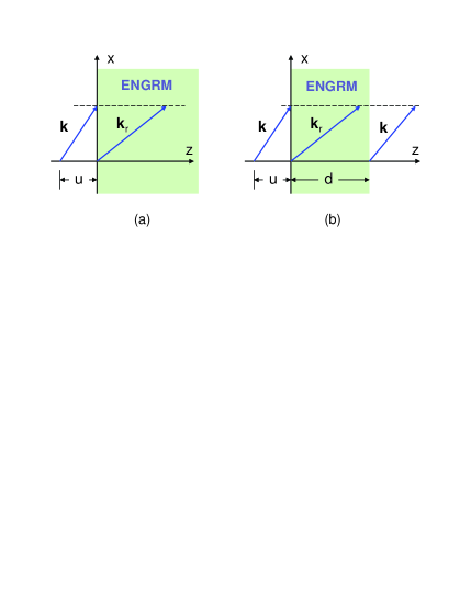
We first consider the case of a single interface which is along the -axis and at as shown in Fig. 1(a). The wave vector of an incident plane wave from vacuum towards the interface makes an angle with the -axis. Here we consider the case that for any incident , there is only one refractive wave vector . Continuity along the interface requires that . A point source is at and with . We now consider another point in the ENGRM at and with . The phase difference between these two points for each incident is with and . According to Fermat’s principle, the formation of an image would require that the total phase be stationary. This restriction can be relaxed for a flat interface. Since the surface is flat, any point of a finite-size source will be imaged to a point with the same -coordinate. Thus and . One only needs to consider . A generalized Fermat’s principle states that an image will be formed if the phase is stationary, . The lens equation for a single interface is
| (1) |
with a material constant
| (2) |
This constant should be positive and independent of the incident angle for a focus without aberration. Thus the following rule for the wave vector refraction at the interface must be obeyed
| (3) |
Here is the integration constant which is also an intrinsic property of the ENGRM. Since in the vacuum , the equi-frequency surface (EFS) of the medium is
| (4) |
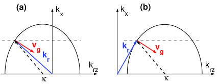
Note that this elliptic dispersion exists only at the operating frequency veselago-comment . In the neighborhood of this frequency , with . The deduction of Eq. (3) from an elliptic EFS requires negative group refraction
| (5) |
together with the causality condition that the energy must flow away from the interface which is illustrated in Fig. 2. The ray vector Landau which represents the direction of group velocity in a medium with elliptic EFS is while with and the incident angle in the vacuum.
The Snell’s law for wave vector loses its meaning in this anisotropic medium. However there is a law for group refraction, which is . At the operating frequency of the flat lens, , , the group refraction law is simply
| (6) |
Thus can be regarded as the effective refractive index. Note that this refraction law is very general and is valid for any as defined by Eq. (2). The proof is the following, . Here we used .
The space inside the medium can be considered to be “optically stretched” in the -direction by a factor of . The waves inside the medium are represented by with and . Thus in the case that , the waves at this frequency will experience a periodicity in the -direction with length scale since the waves are modulated by . This periodicity is the effective periodicity and may not be the actual physical periodicity such as the lattice spacing of a PhC.
We now consider the imaging of an ENGRM slab with thickness as shown in Fig. 1(b). The first surface is at the origin and the second at . A point source is placed at . We consider another point outside the ENGRM slab at . If the value of satisfies the following lens equation
| (7) |
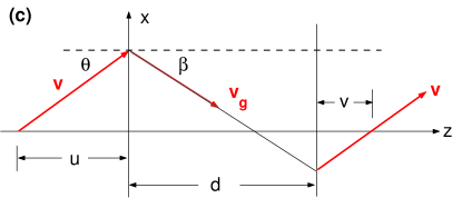
the phase difference is stationary and an image will be formed without aberration. Note that for an ordinary thin curved lens with focal length , the lens equation is . With given value of and slab thickness , the distance between the object and the image outside the slab is fixed, . Once the location of the object is fixed, the position of the image is also fixed, no matter where the slab is placed!
We remark that a flat slab can focus with negative as well as with positive wave vector refraction. The necessary condition for flat lens imaging is negative group refraction. In general, there is not much meaning of Snell’s law for wave vectors for anisotropic media. Only the refraction law for the direction of group velocity Eq. (6) is meaningful and does correspond to ray diagrams. The Veselago-Pendry lens is a special case of our flat lens with , and is the only case that the ray diagram is applicable for the wave vectors.
The lensmaker’s formula Eq. (1) or (7) only provides a necessary condition for imaging. An additional constraint is required for the formation of a “perfect” image, viz. the surface reflection coefficient should vanish, , for far field and should diverge, , for near field. These set the conditions for a perfect flat lens without optical axis. The requirement of no reflection is not essential for a slab to focus far field. The principal conditions for the flat lens to focus light are that Eq. (3) and should be satisfied for all or at least a large range of incident angles. The presence of reflection will make the image dim and may give rise to multiple images. The indefinite indices medium Smith03 can have an elliptic dispersion relation, but in general will not satisfy the flat lens imaging conditions.
The field inside the ENGRM flat lens can also be described by a partial differential equation . The medium can be regarded as a distorted space with the metric . Thus there is an analogy with gravitational lensing where refraction occurs due to the warping of space caused by general relativistic effects, such as in the vicinity of a massive object. It is worth noting that general relativistic effects are observable due to optical refraction.
In the rest of the paper, we will focus on -polarized electromagnetic waves with the electric field in the -direction. In general, the magnetic permeability of the ENGRM should be a tensor, and its relationship to the other material parameters and can be deduced. Here we assume that effective indices and can be used to describe the medium of interest. Due to its symmetry, the ellipsoid can always be transformed to its principal axes BornWolf . For the -polarized waves, the field is in the -plane, only and will enter our discussion. Furthermore, plays a more active role than since the surface reflection coefficient is . Thus to achieve perfect imaging for far field, the effective permeability of ENGRM should be
| (8) |
Only in the case that is isotropic while for , has to be anisotropic and diverges at . For , any finite at results in reduced transmission. Notice that in PhCs including metamaterials, the effective should be anisotropic in general.
To see how the propagating waves are focused, we consider a -polarized point source which is centered at while the two surfaces of the ENGRM slab are at and . If takes the form given by Eq. (8), there will be no reflection for propagating waves and the transmission coefficient through the slab is . The transmitted far field is
| (9) |
Note that and . The image outside the slab is located at . One can see that except for a global phase , the far field of the image is exactly that of the source. The far field inside the slab is
| (10) |
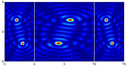
for . Another perfect image is formed inside the slab at . The first surface acts as a mirror with an extra phase . The space inside the ENGRM slab is optically stretched by a factor of . A flat lens imaging is shown in Fig. 3.
Evanescent waves and sub-wavelength imaging For evanescent waves , the complex extrapolation of Eq. (4) gives
| (11) |
with . The transmission coefficient through the flat lens is with . In order to amplify evanescent waves, a singularity must exist in to compensate to certain extent the decay of evanescent waves in the vacuum . In the case of single-interface resonance Pendry ; Luo03 , , , all the evanescent waves will be amplified only if
| (12) |
The images both inside and outside have the same sub-wavelength features of the source. If couldn’t take the above form, sub-wavelength imaging is still possible. At the so-called overall resonance condition Luo03 , , thus , one gets
| (13) |
For , and are all complex with negative real parts. One notices that is flatter than as functions of . In terms of effective indices, the existence of surface modes requires that be negative for -polarization. To amplify evanescent waves, the curve must be very flat Luo03 . This is equivalent to say that the curve should be flat so that the contribution of evanescent waves are constructive for certain window of . The closer is to , the more sub-wavelength features the images will have. Note that for large , the evanescent waves are located in the vicinity of the interfaces for constant .
Realization in real materials We note that no known natural material is found to have negative dispersion. Negative group refraction can be achieved in periodic or quasi-periodic media with nonzero NotePhC . For most media, Eq. (8) and (12) are unlikely to be fulfilled, thus a perfect flat lens is unattainable. Realization using real materials is discussed next.
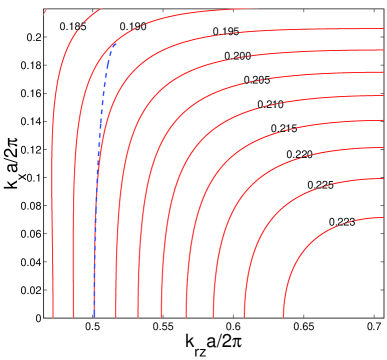
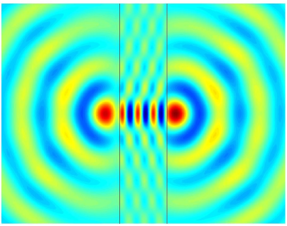
Ordinary material may not have the EFS described by Eq. (4) for all . For an uniaxial crystal, since the group refraction is positive, thus with and . There will be no focus though negative refraction for certain incident angles can be easily achieved Zhang03 . Instead a virtual image will be formed satisfying the same lens equation. However, a PhC could have both an elliptic EFS and negative group refraction for certain windows of at certain frequency. Here we use some general features of PhCs to explain the imaging mechanism. To this end, we consider the first band of a square lattice PhC of unit lattice spacing. For small along the direction, the dispersion can be approximated elliptically as with appropriate constants and (see the dashed line in Fig. 4). At , the upper limit of all-angle negative refraction (AANR) in the first band Luo02 , . Since for AANR with away from , will be smaller, we only concentrate here on the discussion for . To enhance the transmission, the slab thickness can be selected to satisfy the Fabry-Perot resonance condition . The slab is on resonance only for . For large , due to the symmetry of the EFS. A desired large transmission would require to diverge. Thus the image location is bounded and the Fourier components of the object with will be partially lost. This leads to a so-called self-collimation effect for small . Far field images both inside and outside the slab with reasonably good quality will be formed. However, the image inside the PhC is stretched and modulated due to the partial transmission besides the Bloch wave modulation. Even with the removal of Bloch wave modulation, the image inside a PhC will be visible only for large thickness. For evanescent waves at with , one has and while for , . To have substantial sub-wavelength feature of the image, the real part of must take large negative value for small . An example is shown in Fig. 4, which is very similar to Fig. 5 in Ref. Luo02 . The image is confined in the vicinity of the second surface of the PhC slab due to a small value of .
In this paper, we have discussed the group refraction of an anisotropic medium characterized by two materials parameters and . When is a positive constant, the anisotropic medium is an ENGRM and a flat slab of such medium can be used as a focal lens without optical axis and leading to images free of aberration. Our theory of flat lens imaging is a generalization of the Vesalago-Pendry perfect lens and beyond Silin’s formula. The theory is valid for both real and virtual images. This flat lens theory leads to a clear understanding of negative group refraction and flat lens imaging in electromagnetism Parimi03 ; Luo02 , acoustics ZhangLiu , and electron waves. Numerical simulations of homogeneous ENGRMs and of PhCs were carried out supporting our theory.
The lack of optical axis for the flat lens has very broad applications and confers important advantages in optics. Clearly there are no aperture restrictions. There are two characteristics that might be viewed as limitations. The lensmaker’s formula clearly dictates upper bounds to for real image formation. The other limitation is that magnification is always unity. For any medium the lens properties , , and also the working frequency can be obtained by inspection of the EFS. To have high quality image, should be constant and close to unity. The present theory can be used to design tailor-made flat lenses. Extension of our theory to three-dimensions is straightforward.
Work supported by the National Science Foundation and the Air Force Research Laboratories, Hanscom, MA.
References
- (1) B. Mahon, The man who changed everything: The life of James Clerk Maxwell, John Wiley & Sons 2004.
- (2) M. Born and E. Wolf, Principles of Optics, 7th ed., Cambridge University Press (2003).
- (3) E. W. Marchland, Gradient Index Optics, Academic Press, New York (1978).
- (4) P. B. Wilkinson, T. M. Fromhold, R. P. Taylor, and A. P. Micolich, Phys. Rev. Lett. 86, 5466 (2001).
- (5) D. R. Smith, J. J. Mock, A. F. Starr, and D. Schurig, Phys. Rev. E 71, 036609 (2005).
- (6) S. A. Tretyakov, in Negative Refraction: Revisiting Electromagnetics from Microwave to Optics, EPFL Latsis Symposium, Lausanne, Switzerland, 2005, pp.30-35.
- (7) V. G. Veselago, Sov. Phys. Usp. 10, 509 (1968).
- (8) R. A. Silin, Opt. Spectrosc. 44, 109 (1978).
- (9) J. B. Pendry, Phys. Rev. Lett. 85, 3966 (2000).
- (10) R. A. Shelby, D. R. Smith, and S. Shultz, Science 292, 77 (2001).
- (11) E. Cubukcu, K. Aydin, E. Ozbay, S. Foteinopoulou, and C. M. Soukoulis, Nature (London) 423, 604 (2003).
- (12) P. V. Parimi, W. T. Lu, P. Vodo, J. Sokoloff, J. S. Derov, and S. Sridhar, Phys. Rev. Lett. 92, 127401 (2004).
- (13) C. Luo, S. G. Johnson, and J. D. Joannopoulos, Phys. Rev. B 65, 201104(R) (2002).
- (14) P. V. Parimi, W. T. Lu, P. Vodo, and S. Sridhar, Nature (London) 426, 404 (2003).
- (15) J. T. Shen and P. M. Platzman, Appl. Phys. Lett. 80, 3286 (2002).
- (16) W. T. Lu and S. Sridhar, Microwave Opt. Tech. Lett. 39, 282 (2003).
- (17) N. Fang, H. Lee, C. Sun, and X. Zhang, Science 308, 534 (2005).
- (18) D. O. S. Melville and R. J. Blaikie, Opt. Express 13, 2127 (2005).
- (19) Note that the Veselago-Pendry lens also operates at a single frequency for which .
- (20) L. Landau and I.M. Lifshitz, Electrodynamics of continuous media, 2nd Ed. (Elsevier 1984).
- (21) D.R. Smith and D. Schurig, Phys. Rev. Lett. 90, 077405 (2003).
- (22) For a PhC with negative group refraction, is always nonzero. For example for the second band, instead of .
- (23) Y. Zhang, B. Fluegel, and A. Mascarenhas, Phys. Rev. Lett. 91, 157404 (2003).
- (24) C. Luo, S. G. Johnson, J. D. Joannopoulos, and J. B. Pendry, Phys. Rev. B 68, 045115 (2003).
- (25) X. Zhang and Z. Liu, Appl. Phys. Lett. 85, 341 (2004).