Crack Path Prediction in Anisotropic Brittle Materials
Abstract
A force balance condition to predict quasistatic crack paths in anisotropic brittle materials is derived from an analysis of diffuse interface continuum models that describe both short-scale failure inside a microscopic process zone and macroscopic linear elasticity. The derivation exploits the gradient dynamics and translation symmetry properties of this class of models to define a generalized energy-momentum tensor whose integral around an arbitrary closed path enclosing the crack tip yields all forces acting on this tip, including Eshelby’s configurational forces, cohesive forces, and dissipative forces. This condition is validated quantitatively by numerical simulations.
pacs:
62.20.Mk, 46.50.+a, 46.15.-xThe prediction of the path chosen by a crack as it propagates into a brittle material has been a long standing problem in fracture mechanics. This question has been addressed primarily in a theoretical framework where the equations of linear elasticity are solved with zero traction boundary conditions on crack surfaces that extend to a sharp tip refgen . The stress distributions near the tip have universal divergent forms
| (1) |
where are the stress intensity factors for the three standard modes I, II, or III of fracture ( or ) and is the angle between the radial vector of magnitude with origin at the crack tip and the local crack direction. For the crack to propagate, the energy release rate (or crack extension force)
| (2) |
must exceed some material dependent threshold that is theoretically equal to twice the surface energy (), but often larger in practice. Here, is Poisson’s ratio, is the bulk modulus, is the shear modulus, and .
Like other problems in fracture, the prediction of crack paths was first examined BarChe1961 for mode III which is simpler because the antiplane component of the displacement vector is a purely scalar Laplacian field. The stress distribution near the tip, can be expanded as
| (3) |
and the dominant divergent contribution is always symmetrical about the crack direction. This implies that knowledge of cannot predict any other path than a straight one. To avoid this impasse, Barenblatt and Cherepanov BarChe1961 retained the subdominant term , which breaks this symmetry, and hypothesized that a curvilinear crack propagates along a direction where , and hence when the stress distribution is symmetrical about the crack direction. In subsequent extensions of this work, several criteria have been proposed for plane loading, for which the tensorial nature of the stress fields makes it possible to predict non-trivial crack paths purely from the knowledge of the stress-intensity factors GolSal1974 ; CotRic1980 . The generally-accepted condition “” assumes that the crack propagates in a pure opening mode with a symmetrical stress distribution about its local axis GolSal1974 and is the direct analog for plane strain () of the condition for mode III. This “principle of local symmetry” has been rationalized using plausible arguments CotRic1980 but cannot be derived without an explicit description of the process zone, where elastic strain energy is both dissipated and transformed nonlinearly into new fracture surfaces. As a result, how to extend this principle to anisotropic materials, where symmetry considerations have no obvious generalization, is not clear Mar2004 . In addition, path prediction remains largely unexplored for mode III even for isotropic materials.
In this letter, we address the problem of path prediction in the context of continuum models of brittle fracture that describe both short scale failure and macroscopic linear elasticity within a self-consistent set of equations. Such models have already proven capable to reproduce a wide range of phenomena for both antiplane KarLob2004 and plane HenLev2004 loading from the onset of crack propagation at the Griffith threshold to dynamical branching instabilities KarLob2004 and oscillatory HenLev2004 instabilities. From an analysis of these models, we derive a new condition to predict crack paths that is interpreted physically in the context of previous results from the fracture community.
For clarity of exposition, we base our derivation on the phase-field approach of Ref. KKL2001 where the displacement field is coupled to a single scalar order parameter or “phase field” , which describes a smooth transition in space between unbroken () and broken states () of the material. Our approach is sufficiently general, however, to be applicable to a large class of diffuse interface descriptions of brittle fracture. We focus on quasi-static fracture in a macroscopically isotropic elastic medium with negligible inertial effects. Material anisotropy is simply included by making the surface energy, , dependent on the orientation of the crack direction with respect to some underlying crystal axis.
For brevity of notation, we define the four-dimensional vector field for and where are the components of the standard displacement field. The energy density depends on and , where spatial gradients of the displacement contribute to the elastic strain energy and gradients of the phase-field contribute to the surface energy KKL2001 . The equations of motion are derived variationally from the spatial integral of , the total energy of the system, and obey the gradient dynamics
| (4) |
where and for . These Euler-Lagrange equations for are simply the static equilibrium conditions that the sum of all forces on any material element vanish. The fourth equation for is the standard Ginzburg-Landau form that governs the phase-field evolution, where is a kinetic coefficient that controls the rate of energy dissipation in the process zone.
In the present model that describes both microscopic and macroscopic scales, the problem of predicting the macroscopic path of a crack can be posed as an “inner-outer” matching problem. We seek inner solutions of the equation of motion (4) on the scale of the process zone subject to far field boundary conditions imposed by matching these solutions to the standard solutions of linear elasticity on the outer scale of the system . These outer solutions change slowly on a scale where the crack advances by a distance . We can therefore search for inner solutions by rewriting Eq. (4) in a frame translating uniformly at the instantaneous crack speed parallel to the crack direction
| (5) |
We then seek solutions of Eq. (5) with far displacement fields () in the unbroken solid that yield the singular stress distributions defined by Eqs. (1) and (3).
There are two ways to proceed to solve this problem. The first approach, which will be exposed in more details elsewhere, exploits the existence of the stationary semi-infinite crack solution, , for and which is symmetrical about the crack axis. One can then seek solutions of Eq. (5) linearized around this Griffith crack with the driving force for crack advance and symmetry breaking perturbations (, , and the anisotropy of the surface energy ) assumed to be small. Owing to the variational character of the phase-field equations, the linear operator of the resulting linearized problem is self-adjoint and hence has two zero modes, , associated with translations of the Griffith crack. The standard requirement that non-trivial solutions to this problem be orthogonal to the null space of the adjoint linear operator yields two independent solvability conditions (for ).
The second approach, which we adopt here, exploits the variational character of the equations of motion. It yields identical solvability conditions as the first approach when and symmetry breaking perturbations are small, but it is more general since it does not require these quantities to be small. We start from the equality obtained simply from chain rule differentiation,
| (6) |
where and is an arbitrary region of the plane. Using Eq. (5) to eliminate from the integrand of the right-hand-side (r.h.s.), we obtain
| (7) |
The generalized energy-momentum (GEM) tensor
| (8) |
extends the classical energy-momentum tensor of linear elastic fields Esh1975 by incorporating short-scale physics through its additional dependence on the phase-field.
We now consider a region that contains the process zone (crack tip) and write the integral of the divergence of the GEM tensor as a contour integral
| (9) |
We have decomposed the boundary of into: (i) a large loop around the tip in the unbroken material, where () is at a height below (above) the crack axis that is much larger than the process zone size but much smaller than the radius of the contour, , and (ii) the segment that traverses the crack from to behind the tip, as illustrated in Fig. 1. In both integrals, is the contour arclength element and the components of its outward normal.

Eq. (9) provides the basis to predict the crack speed and its path for quasi-static fracture. The can be interpreted as the sum of all forces acting on the crack tip parallel () and perpendicular () to the crack direction, including configurational, cohesive, and dissipative forces, represented by the three integrals terms from left to right, respectively. In the unbroken material where is constant, the tensor reduces identically to the energy-momentum tensor introduced by Eshelby to compute the configurational force on the crack tip treated as a defect in a linear elastic field Esh1975 , and used in subsequent attempts to derive criteria for crack propagation and stability Guretal ; Adaetal1999 ; Ole2003 . Thus, the first integral in Eq. (9) yields the configurational forces
| (10) |
in the limit . The first is the crack extension force and also Rice’s integral Ric1968 . The second is the Eshelby torque Esh1975 , where is the extension force at the tip of a crack extended at a vanishingly small angle from its local direction. This torque tends to turn the crack in a direction that maximizes .
An important new ingredient of the present derivation is the second portion of the line integral () of the GEM tensor that traverses the crack. This integral represents physically the contributions of cohesive forces inside the process zone. To see this, we first note that the profiles of the phase-field and the three components of the displacement can be made to depend only on provided that the contour is chosen much larger than the process zone size and to traverse the crack perpendicularly from to . With this choice, we have that , , along this contour and therefore that, for
| (11) |
where the second equality follows from the fact that spatial gradients parallel to the crack direction () give vanishingly small contributions in the limit and with . This yields the expected result that cohesive forces exert a force opposite to the crack extension force with a magnitude equal to twice the surface energy. An analogous calculation for yields, in the same limit , the other component of the force perpendicular to the crack direction
| (12) |
This force is the direct analog of the Herring torque on grain boundaries Her1951 . This torque tends to turn the crack into a direction that minimizes the surface energy. Substituting the results of Eqs. (10) to (12) into Eq. (9), we obtain the two conditions
| (13) | |||||
| (14) |
where we have used the fact that , and defined the dissipative forces
| (15) |
by letting the area tend to infinity since the integrand vanishes outside the process zone. Eq. (13) predicts the crack speed for close to where is the phase-field profile for a stationary crack KarLob2004 . Eq. (14), in turn, predicts the crack path. and can be generally obtained from Eq. (10), using the known forms of the displacement fields near the tip. The integral yields Eq. (2) for . can also be obtained directly from the expression for . The latter is instructive here to highlight important differences between plane strain and antiplane shear. Consider a straight crack parallel to the axis with stress intensity factors and . Now extend this crack by a length at a small angle from this axis. The new stress intensity factors are given by and to linear order in AmeLeb1992 independent of . Using Eq. (2) with these new stress intensity factors to define , we obtain at once . Substitution in Eq. (14), provides the condition
| (16) |
which determines the crack path. In an isotropic material, this condition reduces to the principle of local symmetry since vanishes trivially, and . The latter follows from the symmetry of the inner phase-field solution for a propagating crack with , , which implies that the product in Eq. (15) is anti-symmetric. In an anisotropic material, however, is generally not symmetrical and only vanishes in the zero velocity limit where .
The same procedure can be repeated for pure antiplane shear where to linear order in Sih1965 where is a numerical constant, and hence . One important difference with plane loading is the divergence of with the crack extension length . This divergence is also reflected in a dependence of the integral in Eq. (10) on the radius of the contour enclosing the tip. Since the only natural cut off for this divergence is the system size, this result seems to imply that the crack path cannot be predicted solely in terms of local conditions at the tip for mode III . We expect, however, this divergence to be cut off in a real experiment by the process zone size due to the irreversible nature of the fracture process. Namely, fracture surfaces at a distance behind the tip larger than should be essentially immobile, which implies that up to a numerical prefactor. Eq. (14) then yields the local symmetry condition in the isotropic limit, where the symmetry of the phase-field profile makes vanish, as explained above. We will present elsewhere numerical results that validate this condition for mode III. We focus in the remainder of this letter on plane strain.
We use a simple anisotropic extension of the phase-field model of Ref. KKL2001 with an energy density
| (17) |
where is the strain tensor and is the strain energy. No asymmetry between dilation and compression is included since this is not necessary here to test our predictions. The broken state of the material becomes energetically favored when exceeds a threshold and is a monotonously increasing function of that describes the softening of the elastic energy at large strain. By repeating the analysis of Ref. KKL2001 , we obtain that where reduces to the isotropic surface energy of Ref. KKL2001 in the limit.
We test our prediction for the initial angle of a kink crack. Eq. (4) is solved numerically using an Euler explicit scheme to integrate the phase-field evolution and a successive over relaxation (SOR) method to calculate the quasi-static displacement fields and at each time step. We used as initial condition a straight horizontal crack of length centered in a strip of length horizontally and vertically, with fixed values of and on the strip boundaries that correspond to the singular stress fields defined by Eq. (1) for prescribed values of and . We used [], a grid spacing , and , where the process zone size . We checked that the results are independent of width and grid spacing.
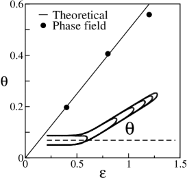
We have verified that the kink angle is well predicted by the local symmetry condition in the isotropic limit, which implies that . In the anisotropic case, we choose and just slightly above such that can be neglected in Eq. (16). Substituting in Eq. (16) and using the fact that for close to , we obtain the prediction for the kink angle which is strictly valid for and . This prediction is in good quantitative agreement with the results of phase-field simulations as shown in Fig. 2.
An interesting implication of our results for crystalline materials is that should exceed some threshold for a cleavage crack to change direction. Using the expected cusp behavior of the surface energy for small angle near a cleavage plane, , Eq. (16) predicts that this threshold is for since this equation cannot be satisfied for any smaller value of for small. It should be hopefully possible to test this prediction experimentally as well as to explore the validity of this new condition on for curvilinear paths. The extension of the present analysis to include inertial effects and to three dimensions where fracture paths are geometrically more complex is an important future direction. Work along this line is presently in progress.
We thank M. Adda-Bedia and J. B. Leblond for valuable discussions. A.K. thanks the hospitality of ENS and support of DOE Grant No. DE-FG02-92ER45471.
References
- (1) K. B. Broberg, Cracks and Fracture (Academic Press, San Diego, 1999).
- (2) G. I. Barenblatt and G. P. Cherepanov, PMM 25, 1110 (1961) [J. Appl. Math. Mech. 25, 1654 (1961)].
- (3) R. V. Goldstein and R. L. Salganik, Int. J. Fract. 10, 507 (1974) and references therein.
- (4) B. Cotterell and J. R. Rice, Int. J. Fract. 16, 155 (1980).
- (5) M. Marder,“Cracks Cleave Crystals” (in press).
- (6) A. Karma, D. Kessler, and H. Levine, Phys. Rev. Lett. 87, 045501 (2001).
- (7) A. Karma and A. Lobkovsky, Phys. Rev. Lett. 92, 245510 (2004).
- (8) H. Henry and H. Levine, Phys. Rev. lett. 93, 105504 (2004).
- (9) J. D. Eshelby, J. Elast. 5, 321 (1975), and earlier references therein.
- (10) M. E. Gurtin and P. Podio-Guidigli, J. Mech. Phys. Solids 44, 1343 (1998).
- (11) M. Adda-Bedia et al., Phys. Rev. E 60, 2366 (1999).
- (12) G. E. Oleaga, J. Mech. Phys. Solids 49, 2273 (2001).
- (13) J. R. Rice, J. Appl. Mech. 35, 379 (1968).
- (14) C. Herring, The Physics of Powder Metallurgy, ed. by W. E. Kingston (McGraw-Hill, New York, 1951), p. 143.
- (15) M. Amestoy and J. B. Leblond, Int. J. Solids Structures 29, 465 (1992), and earlier references therein.
- (16) G. C. Sih, J. Appl. Mech. 32, 51 (1965).