[
Strong effect of surfaces on resolution limit of negative-index “superlens”
Abstract
We show that subwavelength imaging by negative index materials (NIM), related to their “soft” electromagnetic response, is very (and non trivially) sensitive to the surface properties. A minute deviation of dielectric permittivity or magnetic permeability from the ideal values in thin surface layer(s) results in drastic reduction of the resolution limit of a NIM slab. There may be a gap in the polariton spectrum and this would allow establishment of a stationary regime even without losses.
pacs:
78.20.Ci, 42.30.Wb,73.20.Mf,78.66.Bz]
Negative-index materials (NIMs), discussed theoretically by Veselago in 1960s [1], with negative values of both the dielectric permittivity, and permeability should show a negative refraction index in the Snell’s law. This is a result of having the opposite phase and group velocities in NIM, as immediately follows from the Maxwell’s equations. This behavior is very general and was noticed by Maldelshtam already in 1945[2] (see discussion in [3]). NIMs have not been found in nature yet, but artificial metamaterials (metallic wire structures, practically, antenna arrays) have been recently shown to have a negative refraction in the microwave region [4]. The interest in metamaterials has intensified since Pendry’s speculations about “superlensing” with the use of the NIMs[5].
The term “superlensing”, or subwavelength imaging, means a restoration of evanescent waves (exponentially decaying away from the source), that are getting amplified inside NIM and, together with propagating waves, perfectly restore the image. However, this happens at extremely special conditions. To begin with, the perfect restoration of image takes place for ideal NIM only, i.e. for NIM with It is easy to see from geometrical optics [1] that a parallel slab of ideal NIM produces an exact replica of a source if the source is closer to the slab surface than the slab thickness. However, if this property does not exist [6], i.e. even within the geometrical optics the replica will not be perfect. We shall assume below that and will discriminate between the above defined ideal case and a non-ideal one where but Although these two cases are equivalent within geometrical optics, they are essentially different within the wave optics.
Full wave optics consideration of the radiation propagation through ideal NIM slab has been done in Ref. [5]. It has been shown that evanescent waves decaying while propagating from the source transform into increasing (“anti-evanescent”) ones in the slab. Moreover, this amplification is such that the evanescent components are exactly restored in the replica. It could be said, therefore, that the replica remains perfect within the wave optics too. A difficulty with this result was that the stationary state supposed in [5] could not be achieved without absorption [7], and the problem should be reformulated as a non-stationary one [8]. Apart from this, a non-ideal slab with has been shown to not generate the perfect replica [9, 10]. The case of homogeneous has been considered by Haldane[9]. We will argue in this letter that even much more delicate non-ideality, namely, when in very thin surface layers only, and the thickness of the layers being much less that the wavelength, the replica will be distorted similarly to the case of the bulk non-ideality. We will also show that the surface non-ideality, unlike the bulk one, may change the character of the amplification of the evanescent waves making possible a stationary state even without absorption.
The physical reason of amplification of evanescent waves by NIM was nicely commented by Haldane[9]. The mechanism is valid not only for NIM’s but for any slab with surfaces supporting surface electromagnetic (“polariton”) waves, i.e. for any slab with negative supporting polariton with -- polarization. The key point is that the incident radiation may be in resonance with a polariton mode of the NIM slab. Evanescent waves with wavevectors along the surface smaller than the wavevector of the resonant polariton are amplified inside the slab, while the rest is not. The amplitude of the stationary oscillations associated with the resonant mode will formally be infinite, and the contribution of the Fourier harmonics close to this mode will be exaggerated in the image. Consequently, the replica would be distorted. The ideal NIM is an exception, since there the resonance takes place at an infinite wave vector, and the exponentially large increase of the evanescent waves is fully compensated by an exponential decrease of the evanescent wave propagating from the slab surface to the replica image [9]. Moreover, the amplification of the (non-resonant) evanescent waves with finite wavevectors is such that they are exactly restored in the replica. Bearing in mind that, in addition, the propagating waves are not reflected, a perfect replica will be obtained within the wave optics description too (“perfect lensing”) [5].
As we have mentioned, in the non-ideal NIM with case considered by Haldane [9] the resonance is at a finite wave vector and the replica is distorted. What specifically occurs in the replica image in this case has not been discussed. A way to avoid such a discussion is to redefine the term “resolution” by considering the information that, in principle, can be transferred by the waves that have passed through the slab [10]. In this sense, the resolution limit can be defined as , where is the wave vector of the resonant polariton mode. Below we shall follow a similar definition.
Consider a slab of a homogeneous negative index material with , which is parallel to plane and occupies the region with one or two surface layers with thickness(es) and . The layers also have negative permittivity and permeability with We shall consider below an incident -polarized plane wave such that the magnetic field is , where and are related by Maxwell equations as Similar results are obtained for -polarization by replacing by in final formulas. The boundary conditions in the considered case suggest that both and are continuous at the interfaces, where is the corresponding dielectric constant. On the “image side” of the slab the only nonzero component of magnetic field can be written as ( in the case of a surface layer), where is the transmission coefficient, which is of main interest to us. In particular, we are interested in the transmission coefficient for evanescent waves with with their field decaying away from the slab.
For a NIM slab with , we have
| (1) |
If the NIM were ideal (), then , and the above mentioned amplification of all evanescent waves takes place, which exactly compensates for their amplitude decay in the vacuum[5]. In slightly non-ideal NIM () this is already not so, the amplification exists only for the waves with for . This sets the resolution limit [10]
| (2) |
where is the radiation wavelength. This estimate is accurate when The pole in the transmission coefficient corresponds to a surface polariton mode (zero in In the ideal NIM slab this pole corresponds to , while for slightly non-ideal NIM it is at the finite given above [9]. This result tells us immediately that for any practical slightly non-ideal NIM slab the subwavelength imaging is a near-field effect, where one basically needs to use very thin slabs comparable to the wavelength, to see any improvement over standard focusing [10].
Let us now proceed with the study of the effect of the surface layers:
(A) For one surface layer with and we have the exact answer:
| (4) | |||||
(A1) In the case of ideal bulk NIM slab (), the transmission coefficient factorizes: [see Eq. (1)]. The first factor is associated with the ideal NIM slab, while the second one corresponds to the non-ideal surface layer. A thin surface layer limits the resolution as , which is much better that in the case of the non-ideal bulk (as a whole), cf. Eq. (2).
(A2) In the case of slightly non-ideal bulk NIM the transmission coefficient is such that
| (5) |
Now the contributions of bulk and surface non-idealities do not factorize, and we find a qualitatively different situation. The third term signifies the “hybridization” between two polariton solutions that one would have for free bulk and surface layers in vacuum. Interestingly, when the polariton pole in the transmission coefficient vanishes, because there is a gap in the polariton excitations at a particular radiation frequency (where ). When the signs of the parameters coincide, we do have a polariton pole. Yet, in both cases the evanescent signal is amplified, and the resolution is about the same, irrespective of whether there is the polariton resonance or not, since the response of the systems remains soft.
(B) NIM slab with two surface layers. In this general case the full solution can also be obtained, but it is a bit lengthy and not very instructive. We shall look at the most interesting case of ideal NIM slab ( and surface layers with and where
| (6) | |||
| (7) | |||
| (8) |
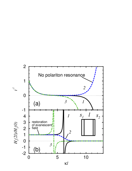
Again, we may have both regimes, with and without the polariton resonance. In particular, if , the polariton pole goes off the real axis, but the “amplification” still exists, Fig. 1b. Although the layers are taken as very thin, , the suppression becomes large due to the cross-terms depending on the thickness of the NIM slab It is sufficient to consider very small deviations from ideal NIM when
| (9) |
and we see that the resolution limit is given by
| (10) |
Here, the logarithm is the sum of which is similar to the logarithm in Eq.(2) for slightly non-ideal slab, and another logarithm of a large argument, . The two logarithms are expected to be comparable, so in practice the situation is not much better than in the case of just a slightly non-ideal NIM slab without any surface inhomogeneity, cf. Eq. (2).
The same results as for the surface inhomogeneity above can also be obtained within a more general framework of accounting for a spatial dispersion and the so-called “additional boundary conditions” [3]. The effect of a spatial dispersion has been mentioned before as one of the limiting factors for the perfect lensing, in the sense that the subwavelength details in the image will be limited by the characteristic length of the microscopic structure of the metamaterial acting as a lens, i.e. the spacing between the active elements, like metallic split-ring resonators [10]. Our result means that the effects of spatial dispersion are much more important than it was recognized before.
Prospects for new optical devices, couplers, modulators, etc. have been driving a strong interest in negative index metamaterials. The metamaterials with metallic split ring resonators have been used in the first demonstration of negative refraction[4], and recently their magnetic response frequencies have been extended to 100 THz ( m)[11] driven by desire to make them work in near-visible and visible frequency range. There is an ongoing effort in the area of sub-wavelength imaging with metallic films[12]. Metallic metamaterials obviously will struggle with losses at optical frequencies. This makes nonmetallic systems such as photonic crystals rather attractive. Photonic crystals made of dielectric materials have been known to behave as NIM in a certain frequency range [13, 14, 15, 16], and this was confirmed experimentally at microwave [17] and near-infrared frequencies ( m)[18]. It is known that applications in this area will face major limiting factors like the deviations of bulk parameters from the perfect lens condition, losses, and a spatial dispersion. In this paper we have shown that minute surface inhomogeneities can also degrade the subwavelength imaging rather drastically.
REFERENCES
- [1] V. G. Veselago, Sov. Phys. Usp. 10, 509 (1968).
- [2] L.I. Mandelshtam, Zh. Eksp. Teor. Fiz. 15, 475 (1945).
- [3] V. M. Agranovich and V.L. Ginzburg, Spatial Dispersion in Crystal Optics and the Theory of Excitons (Interscience, London, 1966), Sec. 10.9.
- [4] R.A. Shelby, D.R. Smith, and S. Schultz, Science 292, 77 (2001).
- [5] J. B. Pendry, Phys. Rev. Lett. 85, 3966 (2000).
- [6] V. G. Veselago, cond-mat/0203451.
- [7] N. Garcia and M. Nieto-Vesperinas, Phys. Rev. Lett. 88, 207403 (2002).
- [8] G. Gomez-Santos, Phys. Rev. Lett. 90, 77401 (2003).
- [9] F.D.M. Haldane, cond-mat/0206420.
- [10] D. R. Smith, D. Schurig, M. Rosenbluth, S. Schultz, S.A. Ramakrishna, and J.B. Pendry, App. Phys. Lett. 82, 1506 (2003).
- [11] S. Linden, C. Enkrich, M. Wegener, J. Zhou, T. Koschny, and C.M. Soukoulis, Science 306, 1351 (2004).
- [12] N. Fang and X. Zhang, App. Phys. Lett. 82, 161 (2003); X. Zhang, to be published.
- [13] M. Notomi, Phys. Rev. B 62, 10 696 (2000).
- [14] S. Foteinopoulou, E. N. Economou, and C.M. Soukoulis, Phys. Rev. Lett. 90, 107402 (2003).
- [15] C. Luo, S.G. Johnson, J.D. Joannopoulos, and J.B.Pendry, Phys. Rev. B 68, 045115 (2003).
- [16] A.L. Efros and A.L. Pokrovsky, cond-mat/0308611.
- [17] E. Cubukcu, K. Aydin, E. Ozbay, S. Foteinopoulou, C.M. Soukoulis, Nature (London) 423, 604 (2003); P.V. Parimi, W.T. Lu, P. Vodo, S. Sridhar, Nature (London) 426, 404 (2003).
- [18] A. Berrier, M. Mulot, M. Swillo, M. Qiu, L. Thylén, A. Talneau, and S. Anand, Phys. Rev. Lett. 93, 073902 (2004).