Mesoscopic Spin Hall Effect in Multiprobe Ballistic Spin-Orbit Coupled Semiconductor Bridges
Abstract
We predict that unpolarized charge current driven through the longitudinal leads attached to ballistic quantum-coherent two-dimensional electron gas (2DEG) in semiconductor heterostructure will induce a pure spin current, which is not accompanied by any net charge flow, in the transverse voltage probes. Its magnitude can be tuned by the Rashba spin-orbit (SO) interaction and, moreover, it is resilient to weak spin-independent scattering off impurities within the metallic diffusive regime. While the polarization vector of the spin transported through the transverse leads is not orthogonal to the plane of 2DEG, we demonstrate that only two components (out-of-plane and longitudinal) of the transverse spin current are signatures of the spin Hall effect in four-probe Rashba spin-split semiconductor nanostructures. The linear response spin Hall current, obtained from the multiprobe Landauer-Büttiker scattering formalism generalized for quantum transport of spin, is the Fermi-surface determined nonequilibrium quantity whose scaling with the 2DEG size reveals the importance of processes occurring on the spin precession mesoscale (on which spin precesses by an angle )—the out-of-plane component of the transverse spin current exhibits quasioscillatory behavior for (attaining the maximum value in 2DEGs of the size ), while it reaches the asymptotic value in the macroscopic regime . Furthermore, these values of the spin Hall current can be manipulated by the measuring geometry defined by the attached leads.
pacs:
72.25.Dc, 73.23.-b, 85.75.NnI Introduction
Current efforts in spintronics are to a large extent directed toward gaining control of electron spin in semiconductor structures, which are ubiquitous in conventional electronics, and exploiting it as a carrier of classical or quantum information. spintronics Although spin physics in semiconductors is an old subject, rashba ; extrinsic_1 spintronics has reignited interest in the role of spin-orbit (SO) couplings in condensed matter systems. While they originate from relativistic corrections to the Schrödinger equation, SO interactions for itinerant electrons in semiconductor nanostructures can be much stronger than for particles moving through electric fields in vacuum. rashba_review ; winkler Therefore, they are envisaged to be a tool for all-electrical rashba_review ; nitta spin current generation and manipulation, where electric fields can be produced to control electron spin in far smaller volumes and on far shorter time scales than it is possible with conventional magnetic field-based spin control. spintronics
Recent theoretically unearthed intrinsic spin Hall effect in hole doped murakami (such as bulk -GaAs or -Ge described by the Luttinger effective Hamiltonian for heavy and light holes), or electron doped sinova (such as 2DEG in -type heterostructures with structure inversion asymmetry which gives rise to the Rashba-type of SO coupling rashba ; rashba_review ; winkler ) semiconductors suggests that pure (i.e., not accompanied by any net dissipative charge current) transverse spin current could be generated in these systems due to longitudinal electric field. The correlation between spin orientation and carrier velocity, induced in this effect in the presence of an external electric field, essentially requires some type of SO coupling which is strong enough to spin-split the Bloch energy bands. murakami
On the other hand, it has been known for a long time extrinsic_1 ; extrinsic_2 that SO dependent scattering off impurities will deflect spin- (spin-) electrons predominantly to the right (left), thereby giving rise to the extrinsic spin Hall effect where pure spin current flows perpendicular to the longitudinal unpolarized charge transport. However, the intrinsic spin Hall current is expected to be several order of magnitude larger than the extrinsic one, thereby promising all-electrical solution to spin injection problems rashba_review and opening new avenues for semiconductor spintronics applications. spintronics
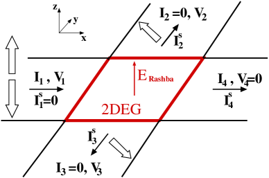
While the properties of the intrinsic spin Hall current have been delineated through the semiclassical analysis of infinite homogeneous SO coupled semiconductor systems in the clean limit, sinova ; murakami guiding experimental detection of such effects requires a quantitative prediction for the spin current flowing through the leads attached to a finite-size sample, as exemplified by the bridge in Fig. 1. This is analogous to profound developments in our understanding of quantum Hall effect ensuing from the comparison of the macroscopic charge transport in bulk samples with the gap in the energy spectrum to the mesoscopic transport through gapless chiral edge states of multiterminal bridges employed in experiments. meso_hall
For example, within a finite-width strip no charge or spin current can flow across its boundaries, so that nonequilibrium spin accumulation accumulation will appear near the lateral edges to generate compensating current in the direction opposite to the spin Hall current. Very recent experiments kato have indeed demonstrated for the first time the existence of such spin accumulation, which has opposite sign on the lateral edges of the wire, as the manifestation of the spin Hall effect(s) in two-terminal devices. Thus, when ideal (i.e., spin and charge interaction free) transverse leads are attached at the lateral edges of the 2DEG region in Fig. 1, pure () spin current should emerge in the probe 2 of the bridge.
Here we predict a novel type of effect which exhibits the spin Hall phenomenology in mesoscopic finite-size structures. The transverse pure spin current in Fig. 1 is induced by injecting unpolarized charge current through the longitudinal leads into the SO coupled central region which contains no impurities. The central region is assumed here to be a finite-size Rashba spin-split 2DEG, which is phase-coherent (i.e., electron is described by a single wave function within the sample) and in the ballistic transport regime where electrons do not feel any electric field while propagating through the 2DEG. Within the 2DEG carriers are subjected to the Rashba type of SO coupling, which is described by the following effective mass Hamiltonian
| (1) |
that takes into account structure inversion asymmetry rashba ; rashba_review (of the confining electric potential and differing band discontinuities at the heterostructure quantum well interface winkler ). Here is the momentum operator in 2D space, is the vector of the Pauli spin matrices, is the strength of the Rashba SO coupling, rashba ; rashba_review ; winkler and is the transverse confining potential.
The paper is organized as follows. In Sec. II we recast the Landauer-Büttiker multiprobe charge current formulas in terms of spin-resolved charge current, which then allows us to introduce the multiprobe spin current formalism that yields the general expression for the linear response spin Hall conductance of the bridge in Fig. 1
| (2) |
in terms of the spin-resolved transmission probabilities between different leads. We apply this formalism to a perfectly clean bridge to demonstrate in Sec. III the existence of three non-zero spin conductances (corresponding to three components , , of the vector of pure spin current flowing through the transverse leads), two of which and represent the signature of the mesoscopic spin Hall effect in Rashba spin-split structures. They are determined by the density of electrons and the Rashba SO coupling strength , as well as by the measuring geometry of the whole device (i.e., interfaces, boundaries, and the attached electrodes). Furthermore, we find two different scaling laws for and , depending on whether the device is smaller or greater than the mesoscale set by the spin precession length on which spin precesses by an angle . Section IV shows that the predicted effect is able to survive weak disorder (introduced as spin-independent scattering off static impurities)—the spin Hall conductances and gradually diminish from their maximum values (set in the clean limit of Sec. III) within the metallic diffusive regime and become negligible as the disorder is increased, but before the onset of strong localization effects is reached in phase-coherent SO coupled 2D structures.
The magnitude of the intrinsic spin Hall effect in infinite homogeneous systems is captured by the spin Hall conductivity which relates pure spin current density , flowing in the -direction and carrying spins polarized solely along the -axis, as a response to the longitudinal externally applied electric field . Using our results from Sec. III and Sec. IV, we analyze in Sec. V if any quantitative connection can be established between the bulk spin Hall conductivity and the spin Hall conductance (i.e., between the intrinsic spin Hall current density , which is not conserved in the bulk and depends on the whole SO coupled Fermi sea, and which we find to be a Fermi-surface quantity and conserved total spin current throughout the ideal leads). This analysis reveals different origins of the mesoscopic spin Hall effect, which is governed by the processes on the mesoscale so_force and represents the nonequilibrium manifestation of SO couplings in confined ballistic semiconductor nanostructures. We conclude in Sec. VI.
II Scattering approach to quantum transport of spin currents in multiprobe geometries
The mesoscopic experiments on quantum Hall bridges in the early 1980s were posing a challenge for theoretical interpretation of multiterminal transport measurements. meso_hall By viewing the current and voltage probes on equal footing, Büttiker buttiker has provided an elegant solution to this problem in the form of a multiprobe formula buttiker ; baranger ; datta_book
| (3) |
which relates, via the conductance coefficients , charge current in probe to the voltages in all other probes attached to the sample. To study the spin-resolved charge currents () of individual spin species , we imagine that each non-magnetic lead in Fig. 1 consists of the two leads allowing only one spin species to propagate (as realized by, e.g., half-metallic ferromagnetic leads). Upon replacement and , this viewpoint allows us to extract the multiprobe formulas for the spin-resolved charge currents pareek ; kiselev , thereby obtaining the linear response relation for spin current flowing through the lead
| (4) | |||||
Below we simplify the notation by introducing the labels and . Furthermore, these coefficients have transparent physical interpretation: is the spin current flowing from the lead with voltage into other leads whose voltages are , while is the spin current flowing from the leads into the lead .
The standard charge conductance coefficients buttiker ; baranger ; datta_book in the multiprobe Landauer-Büttiker formalism Eq. (3) are expressed in terms of the spin-resolved conductances as . Their introduction in 1980s was prompted by the need to describe linear transport properties of a single sample, with specific impurity arrangements and attached to specific probe configuration, by using measurable quantities (instead of the bulk conductivity which is inapplicable to mesoscopic conductors baranger ). They describe total charge current flowing in and out of the system in response to voltages applied at its boundaries.
Regardless of the detailed microscopic physics of transport, conductance coefficients must satisfy the sum rule in order to ensure the second equality in Eq. (3), i.e., the charge current must be zero in equilibrium. On the other hand, the multiprobe spin current formulas Eq. (4) apparently posses a nontrivial equilibrium solution (found in Ref. pareek, ) that would be entirely alien to the Landauer-Büttiker paradigm demanding usage of only measurable quantities. However, when all leads are at the same potential, a purely equilibrium non-zero term becomes relevant for [note that for devices in nonequilibrium the summation in Eq. (4) goes only over leads], canceling all other terms in Eq. (4) to ensure that no unphysical total spin current can appear in the leads of an unbiased (=const.) multiterminal device. spin_hall_ring ; kiselev_theorem
At zero temperature, the spin-resolved conductance coefficients , where summation is over the conducting channels in the leads, are obtained from the Landauer-type formula as the probability for spin- electron incident in lead to be transmitted to lead as spin- electron. The quantum-mechanical probability amplitude for this processes is given by the matrix elements of the transmission matrix , which is determined only by the wave functions (or Green functions) at the Fermi energy. baranger The stationary states of the structure 2DEG + two leads supporting one or two conducting channels can be found exactly by matching the wave functions in the leads to the eigenstates of the Hamiltonian Eq. (1), thereby allowing one to obtain the charge conductance from the Landauer transmission formula. governale However, modeling of the full bridge geometry with two extra leads attached in the transverse direction, as well as existence of many open conducting channels, requires to switch from wave functions to some type of Green function formalism.
For this purpose we represent the Rashba Hamiltonian rashba_review ; winkler of the 2DEG in Fig. 1 in a local orbital basis defined on the lattice (with lattice spacing ) as purity
| (5) | |||||
Here (a unit of energy) is the nearest-neighbor hopping between -orbitals on adjacent atoms located at sites of the lattice. Since momentum operator in the tight-binding representation is , the Rashba SO term (in which stands for the tensor product of operators) introduces the SO hopping energy scale . In a perfectly clean 2DEG the on-site potential energy is , while disordered 2DEG can be simulated via a random variable modeling short-range isotropic scattering off spin-independent impurities.
For non-interacting particle which propagates through a finite-size sample of arbitrary shape, the transmission matrices
| (6) |
between different leads can be evaluated in a numerically exact fashion using the realspin-space Green functions. purity This requires to compute a single object, the retarded Green operator
| (7) |
which becomes a matrix (i.e., the Green function) when represented in a basis introduced by the Hamiltonian Eq. (5). Here are the eigenstates of the spin operator for the chosen spin quantization axis. The matrix elements yield the probability amplitude for an electron to propagate between two arbitrary locations and (with or without flipping its spin during the motion) inside an open conductor in the absence of inelastic processes. Its submatrix , which is required in Eq. (II), consists of those matrix elements which connects the layer of the sample attached to the lead to the layer of the sample attached to the lead . The unit operators and act in the orbital and the spin Hilbert spaces , respectively, which comprise the Hilbert space of a single spinfull particle (via tensor product of vector spaces). The self-energy (-retarded, -advanced, ) account for the “interaction” of an open system with the attached four ideal semi-infinite leads datta_book .
A direct correspondence between the continuous effective Rashba Hamiltonian Eq. (1) [with parabolic energy-momentum dispersion] and its lattice version Eq. (5) [with tight-binding dispersion] is established by selecting close to the bottom of the band (where tight-binding dispersion reduces to the quadratic one), and by using for the orbital hopping which yields the effective mass in the continuum limit. We elucidate further the connection between the standard effective Rashba Hamiltonian in continuous representation Eq. (1) and its lattice version by interpreting the tight-binding parameters in Eq. (5) for particular experimental realization of a 2DEG in semiconductor heterostructures. For example, the InGaAs/InAlAs heterostructure employed in experiments of Ref. nitta, is characterized by the effective mass ( is the free electron mass) and the width of the conduction band eV, which sets meV for the orbital hopping parameter on a square lattice (with four nearest neighbors of each site) and nm for its lattice spacing. Thus, the Rashba SO coupling of 2DEG formed in this heterostructure, tuned to a maximum value nitta eVm by the gate voltage covering the 2DEG, corresponds to the SO hopping in the lattice Hamiltonian Eq. (5).
II.1 General expression for the spin Hall conductance
Since the total charge current depends only on the voltage difference between the leads in Fig. 1, we set one of them to zero (e.g., is chosen as the reference potential) and apply voltage to the structure. Imposing the requirement for the voltage probes 2 and 3 allows us to get the voltages and by inverting the multiprobe charge current formulas Eq. (3). Finally, by solving Eq. (4) for we obtain the most general expression for the spin Hall conductance defined by Eq. (2)
| (8) |
This quantity is measured in the units of the spin conductance quantum (as the largest possible in the transverse leads with only one open conducting channel), which is the counterpart of a familiar charge conductance quantum (as the natural unit for spin-resolved conductance coefficients ).
In contrast to the charge current which is a scalar quantity, spin current has three components because of the vector nature of spin (i.e., different “directions” of spin correspond to different quantum mechanical superpositions of and states). Therefore, we can expect that, in general, the detection of spin transported through the transverse leads of mesoscopic devices will find its expectation values to be non-zero for all three axes. We indeed find in Sec. III and Sec. IV that all three components of the spin current in the transverse leads 2 and 3 are non-zero. However, their flow properties
| (9a) | |||||
| (9b) | |||||
| (9c) | |||||
show that only the - and the -components represent the spin Hall response for the Rashba SO coupled four-terminal bridges. That is, if we connect the transverse leads 2 and 3 to each other (thereby connecting the lateral edges of 2DEG by a wire), only the spin current carrying - and -polarized spins will flow through them, as expected from the general spin Hall phenomenology where nonequilibrium spin Hall accumulation detected in experiments kato has opposite sign accumulation on the lateral edges of 2DEG.
Therefore, to quantify all non-zero components of the vector of transverse spin current in the linear response regime, we introduce three spin conductances , , and (assuming ). They can be evaluated using the same general formula Eq. (8) where the spin quantization axis for , in spin-resolved charge conductance coefficients is chosen to be the -, -, or -axis, respectively. For example, selecting and for the basis in which the Green operator Eq. (7) is represented allows one to compute the -component of the spin current . In accord with their origin revealed by Eq. (9), we denote and as the spin Hall conductances, while is labeled as the “spin polarization” conductance since it stems from the polarization of 2DEG by the flow of unpolarized charge current in the presence of SO couplings accumulation ; ganichev (see also Sec. III).
II.2 Symmetry properties of spin conductances
Symmetry properties of the conductance coefficients with respect to the reversal of a bias voltage or the direction of an external magnetic field play an essential role in our understanding of linear response electron transport in macroscopic and mesoscopic conductors. buttiker ; datta_book For example, in the absence of magnetic field they satisfy (which can be proved assuming a particular model for charge transport datta_book ). Moreover, since the effective magnetic field of the Rashba SO coupling depends on momentum, it does not break the time-reversal invariance which imposes the following property on the spin-resolved conductance coefficients in the multiterminal SO coupled bridges. pareek ; kiselev
In addition, the ballistic four-terminal bridge in Fig. 1 with no impurities posseses various geometrical symmetries. It is invariant under rotations and reflections that interchange the leads, such as: (i) rotation () by an angle () around the -axis for a square (rectangular) 2DEG central region; (ii) reflection in the -plane; and (iii) reflection in the -plane. These geometrical symmetries, together with property, specify solution for the voltages of the transverse leads when condition is imposed on their currents.
The device Hamiltonian containing the Rashba SO term commutes with the unitary transformations which represent these symmetry operations in the Hilbert space : (i) , which performs the transformation , , and interchanges the leads 1 and 4 as well as the leads 2 and 3; (ii) , which transforms the Pauli matrices , , and interchanges leads 2 and 3; and (iii) which transforms , , and exchanges lead 1 with lead 4. The Hamiltonian also commutes with the time-reversal operator [where is the complex conjugation operator].
The effect of these symmetries on the spin-resolved charge conductance coefficients, and the corresponding spin conductances , and expressed in terms of them through Eq. (8), is as follows. The change in the sign of the spin operator means that spin- becomes spin- so that, e.g., will be transformed into . Also, the time reversal implies changing the signs of all spin operators and all momenta so that is equivalent to . Thus, invariance with respect to yields the identities , , and . These symmetries do not imply cancellation of . However, invariance with respect to and implies that and .
These symmetry imposed conditions simplify the general formula Eq. (8) for spin conductances of a perfectly clean Rashba SO coupled four-terminal bridge to
| (10a) | |||||
| (10b) | |||||
| (10c) | |||||
where we employ the result valid for a geometrically symmetric clean bridge. Because this solution for the transverse terminal voltages is violated in disordered bridges, its sample specific (for given impurity configuration) spin conductances cannot be computed from simplified formulas Eq. (10).
It insightful to apply the same symmetry analysis to the bridges with other types of SO couplings. For example, if the Rashba term in the Hamiltonian Eq. (1) is replaced by the linear Dresselhaus SO term due to bulk inversion asymmetry, spintronics no qualitative change in our analysis ensues since the two SO couplings can be transformed into each other by a unitary matrix . In this case, the spin Hall response is signified by and components of the transverse spin current, while . For the Dresselhaus SO coupled bridge, the general expression Eq. (8) simplifies to
| (11a) | |||||
| (11b) | |||||
| (11c) | |||||
The qualitatively different situation emerges when both the Rashba and the linear Dresselhaus SO couplings become relevant in the central region of the bridge since in this case it is impossible to find spin rotation which, combined with the spatial symmetry, would keep the Hamiltonian invariant while only transforming the signs of its spin matrices. Moreover, for such ballistic bridge the condition condition leads to solution for the voltages, whereas imposing the alternative condition generates non-zero charge currents flowing through the transverse leads 2 and 3 together with the spin currents [for which no simple relations akin to Eq. (9) can be written in either of these cases].
III Transverse pure spin currents in ballistic bridges
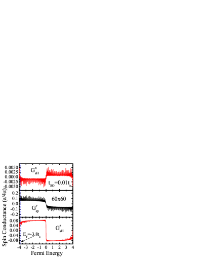
Figures 2, 3, and 4 demonstrate that the spin Hall conductance is not universal— depends on the 2DEG parameters such as the density of charge carriers (i.e., the Fermi energy ), the Rashba SO coupling , and the system size . Furthermore, due to the sensitivity of spin dynamics in confined SO coupled ballistic systems to the boundaries and interfaces, chao it can also be affected by the measuring geometry.

Nevertheless, we find in Fig. 3 that all square 2DEG samples of the size , where is the spin precession length, exhibit approximately the same . Therefore, we pay special attention to the intertwined effect of and brought about by the fact that SO couplings introduce a characteristic length scale into the bridge—the spin precession length over which spin precesses by an angle (i.e., the state evolves into ). In the case of the Rashba SO coupling, is the difference of Fermi wave vectors for the spin-split transverse energy subbands of a quantum wire. This quantity is the same for all subbands of the quantum wire in the case of parabolic energy-momentum dispersion so that single parameter
| (12) |
characterizes the whole structure. For example, the mesoscale sets the characteristic length for the evolution of the nonequilibrium spin polarization in the course of transport through the ballistic, chao as well as the diffusive SO coupled structures (which are sufficiently wide and weakly disordered purity ) where it plays the role of the disorder-independent D’yakonov-Perel’ spin relaxation length. spintronics ; chao ; wees

In this section we study systematically the dependence of the spin Hall and spin polarization conductances on the first three basic parameters of the bridge, while leaving the effect of the disorder strength for Sec. IV (cf. Fig. 5), and the influence of the measuring geometry determined by the attached leads to Sec. V (cf. Fig. 6).
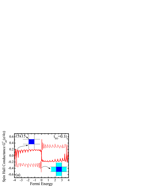
III.1 Fermi energy dependence of the spin Hall conductance
The spin conductances plotted in Fig. 2 are an odd function of the Fermi energy and, therefore, have to vanish , at the half-filled band . This feature is a consequence of the spin current being defined as the difference of charge currents of spin- and spin- electrons and particle-hole symmetry of the tight-binding Hamiltonian Eq. (5). That is, the spin current carried by electrons above the half-filling can be interpreted as the propagation of positively charged holes which move in the opposite direction, and have opposite spin, to that of electrons. To evade artifacts of the tight-binding energy-momentum dispersion, which can enhance the spin Hall conductance as we approach the band center, we highlight in Fig. 2 the values of spin conductances at the Fermi energy chosen for our subsequent analysis. When zero-temperature unpolarized charge quantum transport is determined by the states at this , which is close to the bottom of the band , the injected quasiparticles have quadratic and isotropic energy-momentum dispersion which characterizes the Hamiltonians in effective mass approximation, such as the Rashba one in Eq. (1). Also the Fermi wavelength corresponding to the Fermi energy measured from the band bottom is much greater than the lattice spacing so that possible artifacts of the discretization are avoided.
III.2 Rashba SO coupling dependence of the spin Hall conductances
Considerable interest for exploiting the Rashba SO coupling rashba ; rashba_review ; winkler for semiconductor spintronics applications stems from the possibility to tune its strength via an external gate electrode, nitta thereby manipulating spin solely by electrical means. A surprising early result in the theory of the intrinsic spin Hall effect is apparent ‘universality’ of (obtained from the linear response theory for the clean Rashba Hamiltonian of an infinite 2DEG) in the sense that it does not depend on the strength of the SO coupling. sinova However, when scattering of impurities is taken into account in the limit , one recovers loss the physically expected result .
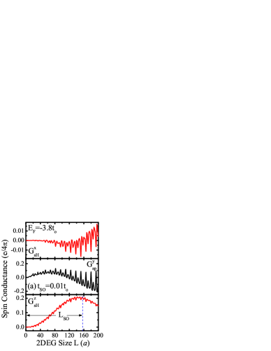
Our exact treatment of transport of non-interacting quasiparticles through a clean finite-size system does not face any technical impediments in locating the lower limit on the strength of SO coupling capable of inducing the non-negligible spin Hall conductance , as shown in Fig. 3. Although realistic Rashba SO coupling strengths in current experiments can be tuned within the range (see Sec. II), we also show in the same Figure the upper limit of large values of beyond which all three components of the transverse spin current vanish due to the carrier reflection purity ; governale at the interface between the ideal lead with and the sample with strong SO coupling . The maximum for square shaped 2DEGs attached to ideal semi-infinite leads is obtained for samples of the size , which connects this dependence with the finite-size scaling properties of discussed in the next section.
III.3 Finite-size scaling of the spin Hall conductances
Figure 3 emphasizes the importance of the spin precession length scale for the spin Hall effect in ballistic semiconductor nanostructures. That is, the spin Hall conductance is increasing non-monotonically with the system size for , attaining the maximum value . In such samples with , the other spin Hall conductance is negligible. The emergence of component of the spin Hall current can be understood heuristically by invoking the semiclassical picture involving the transverse SO force operator so_force
| (13) |
and studying its effect on the propagation of spin-polarized wave packets. so_force This spin-dependent terms here are generated by the Rashba SO coupling term in the single-particle Hamiltonian of a clean 2DEG. Its expectation values in the wave packets (spin-polarized along the -axis, and ) shows that spin- and spin- injected electrons will be deflected in opposite transverse directions (e.g., spin- is initially so_force deflected to the right). Moreover, their spins are forced into precession since injected , states are not the eigenstates of the Zeeman term , where the Rashba effective magnetic field remains nearly parallel to the -axis due to the transverse confining potential governale ; purity .
The precession of the deflected spins is responsible for the oscillatory character so_force of the SO “force” (viewed as the expectation value of the SO force operator in the spin-polarized wave packet states) which changes sign along the wire. Thus, such -dependent spin-deflecting “force” can induce the change in the sign of the spin Hall current as a function of the system size, as shown in Fig. 3(b) for strong SO coupling . In the case of weaker SO couplings , the spin Hall conductance oscillates for while remaining positive, as exemplified by Fig. 3(a). Note that in the convention of multiprobe spin current formulas Eq. (4), positive spin Hall conductance means that spin current is flowing out of the lead 2 because spin- electrons are deflected to the right (i.e., toward the electrode 3 if injected from the electrode 1) and spin- electrons are deflected to the left, as expected from Eq. (13).
The semiclassical picture of the SO “force” also explains the symmetry properties of the spin Hall current with respect to the voltage bias reversal [i.e., the reversal of the momentum in Eq. (13)] or the reversal of the sign of the Rashba SO coupling, . These two features make it possible to differentiate accumulation ; so_force between the - and the -component of the spin Hall current in the transverse leads since and , which stem from the properties of the effective magnetic field inducing the spin precession under these transformations.
The -component of the transverse spin current satisfies , signaling that is of completely different origin. It stems from nonequilibrium spin accumulation, which has the same sign on the lateral edges of 2DEG, accumulation induced when unpolarized charge current is flowing through the Rashba SO coupled 2DEG attached to two electrodes. accumulation ; ganichev ; shytov Thus, when transverse leads are connected to the lateral edges the 2DEG, the spin-dependent chemical potential wees on the edges will push the spin current into the leads. Since this chemical potential is the same on both lateral edges, connecting the edges by a wire would not lead to any net spin flux through it, in sharp contrast to the currents and that will transport spin through such wire as a signature of the spin Hall effect(s) phenomenology.
IV Transverse pure spin currents in disordered bridges
The most conspicuous difference between the “old” extrinsic extrinsic_1 ; extrinsic_2 effect (in paramagnetic metals or semiconductors without SO splitting of quasiparticle energies) and the “new” intrinsic spin Hall effect (in semiconductors with sufficiently large SO splitting of quasiparticle energies) is that the former vanishes in the ballistic limit, while the later persists even when no skew-scattering at impurities takes place. murakami ; sinova However, the distinction between the two spin Hall effects turns out to be ambiguous loss ; sugimoto when SO energy splitting ( is the Fermi wave vector) is smaller than the disorder induced broadening of the energy levels (where is the transport lifetime).
Moreover, the resilience of the intrinsic effect to scattering off static impurities has become a major issue in current debates over the observability of spin Hall current in realistic samples of 2DEG with the Rashba SO interaction shytov ; loss ; sugimoto ; inoue ; chalaev or in hole-doped bulk 3D semiconductors. murakami2004 ; loss Early (lowest order) perturbative treatment of the semiclassical Boltzmann diffusive transport in infinite homogeneous Rashba spin-split 2DEG has revealed that could survive disorder effects with the proviso that , while being gradually reduced from the ‘universal’ value with increasing disorder strength. loss However, when vertex corrections are included in the perturbative expansion, the intrinsic effect turns out to be suppressed at arbitrarily small disorder , as revealed by a multitude of transport approaches inoue applied to any system with linear in momentum SO energy splitting (note that such cancellation induced by the ladder vertex corrections does not occur when SO coupling contains higher-order momentum terms murakami2004 ).
The vanishing intrinsic spin Hall current density is also found at the weak localization level in the perturbative expansion in small parameter chalaev , as well as in the bulk of 2DEG (infinite in the transverse direction) attached to two massive electrodes in the longitudinal direction where, nevertheless, macroscopic inhomogeneities can induce non-zero within the spin relaxation length wide region around the electrode-2DEG interfaces. shytov Finally, recent reexamination sugimoto of these results in a vast range of ratios of the SO coupling induced and the disorder induced energy scales confirms that is indeed suppressed in both the clean and dirty limits , while being able to attain a non-zero optimum value at .
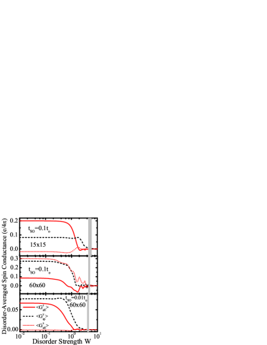
Here we shed light on the effect of disorder on the spin Hall current , whose maximum value is set by the SO coupling effects in ballistic transport regime through multiprobe mesoscopic structures, by introducing spin-independent static random potential into the 2DEG region of Fig. 1 and studying the disorder-averaged conductances , , in the crossover from the quasiballistic to the localized transport regime. The inclusion of all transport regimes is made possible by employing the exact single-particle spin-dependent Green function Eq. (7) which encompasses all quantum-interference effects at arbitrary and in a finite-size device, rather than treating only the lowest order (semiclassical) effects of the disorder loss ; inoue ; shytov ; sugimoto or weak localization quantum corrections. chalaev Figure 5 suggests that mesoscopic spin Hall conductances are unaffected by weak disorder, and they will gradually diminish toward negligible values only at which is deep inside the diffusive metallic regime. Here the semiclassical mean free path (at the selected Fermi energy ) is applicable within the Boltzmann transport regime allen .
The often quoted mantra—all quantum states of disordered non-interacting electrons in two-dimensions are localized—means in practice that the localization length is finite at arbitrary disorder strength. asada Thus, the two-probe (charge) conductance of a sufficiently large 2DEG with impurities will decay exponentially fast . The two exceptions are quantum Hall 2DEG (where delocalized states exist in the center of a Landau level meso_hall ) and 2D systems where strong enough SO coupling can induce the metallic phase at weak disorder. asada We delineate in Fig. 5 the boundaries asada of the localization-delocalization transition to demonstrate that spin Hall conductances will vanish upon increasing disorder before 2DEG is pushed into the realm of strong localization where is trivially expected.
V Mesoscopic spin Hall conductance vs. intrinsic spin Hall conductivity
Both the intrinsic and the mesoscopic spin Hall effect originate from the SO coupling terms in Hamiltonians of clean semiconductor systems. Since conductivity and conductance have the same unit in two dimensions, one might naïvely expect that since it is tempting to connect the total spin Hall current with the spin current density integrated over the cross section, , and use to find that should not scale with the system size. If, on the other hand, mesoscopic spin Hall current in Rashba SO coupled devices is due to the edge spin currents near the contacts with the longitudinal leads, shytov the same arguments would lead to which decreases with the 2DEG size.
In contrast to these naïve expectations, Figure 3 reveals more complicated scaling behavior of in the “mesoscopic” regime where spin Hall conductance oscillates for , and reaches asymptotic value (up to small oscillations around it due to phase-coherent and ballistic nature of transport) in the “macroscopic” regime . The semiclassical picture of the deflection of spin densities involving the SO “force” Eq. (13) offers an explanation of these oscillations of the spin Hall conductance as being due to the change in sign of such “force” deflecting the spin which at the same time is precessing, as elaborated in Sec. III.3. The decay of the SO “force” magnitude so_force while the spin is moving along the wire, which arises due to spin decoherence in ballistic SO coupled systems, chao ; purity is responsible for the saturation of spin Hall conductance in large samples with strong SO coupling.
A closer look reveals further fundamental differences between and . The intrinsic spin Hall effect, murakami ; sinova which is driven by an external electric field penetrating infinite homogeneous systems in the clean limit, loss ; sugimoto is essentially a semiclassical phenomenon where spin current is generated by the anomalous velocity (due to the Berry phase in momentum space) of Bloch wave packets without requiring the shift of the electron distribution function from equilibrium. zhang Such unusual properties of carried by the whole SO coupled Fermi sea, which depends only on the equilibrium distribution function and spin-split band structure, murakami ; sinova have lead to arguments that the intrinsic spin Hall current is an equilibrium current which does not actually transport spin between two points in space. zhang ; rashba_eq In fact, such , which does not induce spin accumulation or can be employed for spin injection, is found in SO coupled systems without any applied electric field rashba_eq or obvious sources of dissipation, insulator which is compatible with time-reversal invariance since does not change sign under the time-inversion transformation.
On the other hand, the mesoscopic spin Hall current is a Fermi-surface quantity at zero temperature [i.e., the contribution to in Eq. (8) from Green functions Eq. (7) evaluated at energies is zero] and a genuine nonequilibrium response because no total spin currents can flow throughout the leads of a multiterminal device in equilibrium spin_hall_ring ; kiselev_theorem (as discussed in Sec. II). Moreover, the induction of can never be “dissipationless” murakami ; insulator since in Eq. (8) is expressed in terms of the spin-resolved charge conductance coefficients whose non-zero values, even in perfectly clean systems where is set entirely by the sample geometry baranger and interfaces at which SO coupling changes abruptly, governale ; purity encode the information about dissipation occuring in remote huge reservoirs thermalizing electrons to ensure the steady-state transport. That is, in the Landauer setup current is limited by quantum transmission through a potential profile while power is dissipated non-locally in the reservoirs. baranger Note also that in the four-terminal devices of Fig. 1, the external bias voltage only shifts the relative chemical potentials of the reservoirs into which the longitudinal leads eventually terminate so that electrons do not feel any electric field in the course of ballistic propagation through clean 2DEG central region.

The inability to connect bulk conductivity (which relates local current density to the electric field, ) to conductance measured in experiments (which relates the total current to the voltage drop, ) is encountered in some charge transport situations as well: (i) in the ballistic regime conductivity does not exist as a local quantity and only the conductance plays a role; (ii) in phase-coherent diffusive conductors quantum corrections to the conductivity emerge which are non-local on the dephasing scale that can be much greater than the mean free path (typically m below which the inelastic processes become suppressed at low enough temperatures K), so that concept of local conductivity loses its meaning. Although our devices in Sec. III are both in the ballistic and phase-coherent regime, the principal obstacle in connecting the intrinsic spin Hall conductivity and mesoscopic spin Hall conductance lies in the fact that spin is not conserved in SO coupled systems. Thus, the plausibly defined spin current-density operator (symmetrized product of the Pauli matrices and the velocity operator which yields a Hermitian operator), employed in different computational schemes for the bulk spin Hall conductivity, murakami ; sinova ; loss ; rashba_eq ; inoue ; chalaev ; shytov ; sugimoto lacks rigorous theoretical justification and standard physical interpretation because it does not satisfy the continuity equation with the spin density operator. murakami ; shytov ; rashba_eq
While the relation of the spin current density (as the expectation value of the corresponding “controversial” spin current-density operator) flowing through the SO coupled system to real spin transport and spin accumulation is far from obvious, the pure spin current , which we define within the asymptotic region of the leads with , is conserved quantity so that does not change on different transverse cross sections throughout the lead 2. Such pure spin currents flowing through the region with no SO coupling have transparent physical interpretation: If all spin- electrons move in one direction, while an equal number of spin- move in the opposite direction, the net charge current vanishes while spin current can be non-zero. In fact, they have been created and detected in recent optical pump-probe experiments. stevens2003
Even in the semiclassical transport regimes at higher temperatures (where ), the presence of SO coupling emphasizes the demand to treat the whole device geometry when studying the dynamics of transported spin densities. wees For example, the decay of nonequilibrium spin polarizaions in ballistic or disordered quantum wires is highly dependent on the transverse confinement effects purity or chaotic vs. regular boundaries of clean quantum dots. chao This is to be contrasted with the conventional D’yakonov-Perel’ spin relaxation mechanism spintronics in unbounded diffusive systems where the decay of spin polarization is determined solely by the SO coupling and elastic spin-independent scattering of charges on the impurities in the bulk. chao Also, the eigenstates governale of SO coupled wires substantially differ from the ones of the infinite 2DEG since is almost parallel to the transverse direction governale ; purity ; so_force (in contrast to the infinite 2DEG where no unique spin quantization axis exists sinova ). These transverse confinement effects are found in Sec. III.3 to be responsible for the non-zero component of the mesoscopic spin Hall current, which is quite different from property of the intrinsic spin Hall effect in infinite homogeneous systems.
The mesoscopic transport techniques, developed to treat the whole measuring geometry as demanded by quantum coherence effects and non-local nature of transport measurements in phase-coherent devices, baranger are well-suited to handle all relevant details of the spin Hall bridges, as applied in Sec. II to spin transport. We investigate this issues further in Fig. 6 by studying the effect of measuring geometry on the maximum value of the spin Hall conductance in the four-probe bridges with 2DEG, where we employ the leads containing finite region within which the Rashba SO coupling is switched on adiabatically (via linear function) from to the value it acquires in the 2DEG. Compared with our standard setup from Fig. (1), the usage of such electrodes would enhance the spin Hall effect since reflection at interfaces where changes abruptly is greatly reduced.
VI Concluding Remarks
In conclusion, we have delineated features of a novel type of spin Hall effect in four-terminal mesoscopic structures where unpolarized charge current driven through the longitudinal ideal (with no spin and charge interaction) leads attached to clean semiconductor region with strong enough homogeneous SO coupling induces a pure spin current in the transverse voltage probes (with zero net charge flow through them). The spin carried by the transverse spin Hall current in devices where electrons are subjected to the Rashba-type of SO coupling within the central region has both out-of-plane and in-plane non-zero components of its polarization vector. The spin Hall current depends on the strength of the Rashba SO coupling. Furthermore, the maximum value of the spin Hall conductance is always achieved for the square samples of the size , where spin precession length can be tuned by changing the Rashba SO coupling via the gate electrode covering the 2DEG.
Although apparently similar to recently predicted intrinsic spin Hall effect (as a semiclassical phenomenon in infinite homogeneous clean SO coupled systems), the mesoscopic pure spin Hall current predicted here has fundamentally different properties: It is a genuine nonequilibrium and Fermi-surface quantity which depends on the whole device (i.e., interfaces and boundaries) and measuring geometry (e.g., it can be enhanced by the leads where SO coupling is adiabatically switched on within a finite region). Its non-trivial finite-size scaling regimes in samples smaller and larger than highlight the importance of processes so_force involving spin dynamics on this mesoscale for the generation of spin Hall current in ballistic multiprobe nanostructures. In contrast to the bulk intrinsic spin Hall conductivity of the Rashba spin-split 2DEG, mesoscopic spin Hall conductances are able to survive weak scattering off impurities, gradually decaying within the metallic diffusive transport regime.
Note added.— Upon completion of this work we have become aware of Ref. sheng, where similar mesoscopic approach to spin Hall effect has been undertaken for different four-probe structure—an infinite Rashba SO coupled wire with two transverse ideal leads attached—and analogous conclusions have been reached regarding its resilience to disorder effects.
Acknowledgements.
We are grateful to J. Inoue and A. Shytov for important insights. This research was supported in part by ACS grant No. PRF-41331-G10.References
- (1) I. Žutić, J. Fabian, and S. Das Sarma, Rev. Mod. Phys. 76, 323 (2004).
- (2) E.I. Rashba, Fiz. Tverd. Tela 2, 1224 (1960) [Sov. Phys.-Solid State 2, 1109 (1960)].
- (3) M. I. D’yakonov and V. I. Perel’, JETP Lett. 13, 467 (1971).
- (4) E. I. Rashba, Physica E 20, 189 (2004).
- (5) R. Winkler, Spin-Orbit Coupling Effects in Two-Dimensional Electron and Hole Systems (Springer, Berlin, 2003); P. Pfeffer, Phys. Rev. B 59, 15902 (1998).
- (6) J. Nitta, T. Akazaki, H. Takayanagi, and T. Enoki, Phys. Rev. Lett. 78, 1335 (1997).
- (7) S. Murakami, N. Nagaosa, and S.-C. Zhang, Science 301, 1348 (2003); Phys. Rev. B 69, 235206 (2004).
- (8) J. Sinova, D. Culcer, Q. Niu, N. A. Sinitsyn, T. Jungwirth, and A. H. MacDonald, Phys. Rev. Lett. 92, 126603 (2004).
- (9) J. E. Hirsch, Phys. Rev. Lett. 83, 1834 (1999); S. Zhang, Phys. Rev. Lett. 85, 393 (2000).
- (10) D. C. Glattli in High Magnetic Fields: Applications in Condensed Matter Physics and Spectroscopy, edited by C. Berthier, L. P. Lévy, and G. Martinez (Springer, Berlin, 2002).
- (11) B. K. Nikolić, S. Souma, L. P. Zârbo, and J. Sinova, cond-mat/0412595.
- (12) Y. K. Kato, R. C. Myers, A. C. Gossard, and D. D. Awschalom, Science 306, 1910 (2004); J. Wunderlich, B. Kaestner, J. Sinova, and T. Jungwirth, Phys. Rev. Lett. 94, 047204 (2005).
- (13) B. K. Nikolić, L. P. Zârbo, and S. Welack, cond-mat/0503415.
- (14) M. Büttiker, Phys. Rev. Lett. 57, 1761 (1986).
- (15) H. U. Baranger and A. D. Stone, Phys. Rev. 40, 8169 (1989).
- (16) S. Datta, Electronic transport in mesoscopic systems (Cambridge University Press, Cambridge, 1995).
- (17) T. P. Pareek, Phys. Rev. Lett. 92, 076601 (2004).
- (18) A. A. Kiselev and K. W. Kim, J. Appl. Phys. 94, 4001 (2003).
- (19) S. Souma and B. K. Nikolić, Phys. Rev. Lett. 94, 106602 (2005).
- (20) A. A. Kiselev and K. W. Kim, Phys. Rev. B 71, 153315 (2005).
- (21) M. Governale and U. Zülicke, Solid State Comm. 131, 581 (2004).
- (22) B. K. Nikolić and S. Souma, Phys. Rev. B 71, 195328 (2005).
- (23) S. D. Ganichev, S. N. Danilov, P. Schneider, V. V. Bel’kov, L. E. Golub, W. Wegscheider, D. Weiss, W. Prettl, cond-mat/0403641; V. M. Edelstein, Solid State Commun. 73, 233 (1990); J. I. Inoue, G. E. W. Bauer, and L. W. Molenkamp, Phys. Rev. B 67, 033104 (2003).
- (24) C.-H. Chang, A. G. Mal’shukov, and K. A. Chao, Phys. Rev. B 70, 245309 (2004); O. Zaitsev, D. Frustaglia, and K. Richter, Phys. Rev. Lett. 94, 026809 (2005).
- (25) M. Zaffalon and B. J. van Wees, Phys. Rev. B 71, 125401 (2005).
- (26) E. G. Mishchenko, A. V. Shytov, and B. I. Halperin, Phys. Rev. Lett. 93, 226602 (2004).
- (27) J. Schliemann and D. Loss, Phys. Rev. B 69, 165315 (2004).
- (28) N. Sugimoto, S. Onoda, S. Murakami, and N. Nagaosa, cond-mat/0503475.
- (29) J. I. Inoue, G. E. W. Bauer, and L. W. Molenkamp, Phys. Rev. B 70, 041303(R) (2004); R. Raimondi and P. Schwab, Phys. Rev. B 71, 033311 (2005); A. G. Mal’shukov and K. A. Chao, Phys. Rev. B 71, 121308(R) (2005); E. I. Rashba, Phys. Rev. B 70, 201309(R) (2004); O. V. Dimitrova, cond-mat/0405339; A. Khaetskii, cond-mat/0408136.
- (30) O. Chalaev and D. Loss, cond-mat/0407342.
- (31) S. Murakami, Phys. Rev. B 69, 241202(R) (2004).
- (32) S. Zhang and Z. Yang, Phys. Rev. Lett. 94, 066602 (2005).
- (33) E. I. Rashba, Phys. Rev. B 70, 161201(R) (2004); Phys. Rev. B 68, 241315(R) (2003).
- (34) S. Murakami, N. Nagaosa, S.-C. Zhang, Phys. Rev. Lett. 93, 156804 (2004).
- (35) M. J. Stevens, A. L. Smirl, R. D. R. Bhat, A. Najmaie, J. E. Sipe, and H. M. van Driel, Phys. Rev. Lett. 90, 136603 (2003).
- (36) Y. Asada, K. Slevin, and T. Ohtsuki, Phys. Rev. Lett. 89, 256601 (2002).
- (37) B. K. Nikolić and P. B. Allen, Phys. Rev. B 63, 020201(R) (2000).
- (38) L. Sheng, D. N. Sheng, and C. S. Ting, Phys. Rev. Lett. 94, 016602 (2005).