Present address: ]Department of Physics and Astronomy, Michigan State University, East Lansing, Michigan 48824, USA
Coherent dynamics of a flux qubit coupled to a harmonic oscillator
In the emerging field of quantum computation1 and quantum information, superconducting devices are promising candidates for the implementation of solid-state quantum bits or qubits. Single-qubit operations2-6, direct coupling between two qubits7-10, and the realization of a quantum gate11 have been reported. However, complex manipulation of entangled states such as the coupling of a two-level system to a quantum harmonic oscillator, as demonstrated in ion/atom-trap experiments12,13 or cavity quantum electrodynamics14 has yet to be achieved for superconducting devices. Here we demonstrate entanglement between a superconducting flux qubit (a two-level system) and a superconducting quantum interference device (SQUID). The latter provides the measurement system for detecting the quantum states; it is also an effective inductance that, in parallel with an external shunt capacitance, acts as a harmonic oscillator. We achieve generation and control of the entangled state by performing microwave spectroscopy and detecting the resultant Rabi oscillations of the coupled system.
The device was realized by electron-beam lithography and metal evaporation. The qubit-SQUID geometry is shown in Fig. 1a: a large loop interrupted by two Josephson junctions (the SQUID) is merged with the smaller loop on the right-hand side comprising three in-line Josephson junctions (the flux qubit)15. By applying a perpendicular external magnetic field, the qubit is biased around , where is the flux quantum. Previous spectroscopy16 and coherent time-domain experiments6 have shown that the flux qubit is a controllable two-level system with ‘spin-up/spin-down’ states corresponding to persistent currents flowing in ‘clockwise/anticlockwise’ directions and coupled by tunneling. Here we show that a stronger qubitSQUID coupling allows us to investigate the coupled dynamics of a ‘qubitharmonic oscillator’ system.
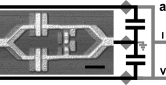


The qubit Hamiltonian is defined by the charging and Josephson energy of the qubit outer junctions ( and where and are their capacitance and critical current)16. In a two-level truncation, the Hamiltonian becomes where are the Pauli matrices in the spin-up/spin-down basis, is the tunnel splitting and ( is the qubit maximum persistent current and is the superconductor phase across the three junctions). The resulting energy level spacing represents the qubit Larmor frequency . The SQUID dynamics is characterized by the Josephson inductance of the junctions pH, shunt capacitance pF (see Fig. 1a) and self-inductances pH of the SQUID and shunt-lines. In our experiments, the SQUID circuit behaves like a harmonic oscillator described by , where is called the plasma frequency and () is the plasmon annihilation (creation) operator. Henceforth represents the state with the qubit in the ground() or excited () level, and the oscillator on the level (). The corresponding level diagram is sketched in Fig. 1b (inset). The coupling between the qubit and the oscillator originates from the current distribution in the shared branches (Fig. 1a) and gives rise to an interaction Hamiltonian with GHz in our device17 (the estimated qubit-SQUID coupling is pH).
Measurements are performed at T=25 mK using low-noise circuitry to minimize decoherence, relaxation and thermal activation. The system is first initialized by allowing it to relax to the ground state. With successive resonant microwave pulses we achieve controlled superposition of various states, as shown below. The readout6 is performed by applying a short current pulse ( ns) and by monitoring whether the SQUID switches to the finite-voltage state. After averaging ty–pically 10000 readouts, we obtain the probability () which for properly-chosen parameters is proportional to the excited state occupancy. In the following, we first show the spectroscopy of the coupled qubitoscillator system and Rabi oscillations of the qubit. Next we demonstrate coherent dynamics of the coupled system.
We performed spectroscopy of the coupled qubitoscillator system by applying a long (300 ns) microwave pulse with various frequencies and measuring the SQUID switching probability. Peaks and dips are observed and their resonant frequencies as a function of are given in Fig. 1b. We obtain one manifold of three resonances spaced by GHz. This frequency coincides with the designed oscillator eigenfrequency . In addition, we observe a spectroscopic peak or dip that depends only weakly on the magnetic field (circles in Fig. 1b). For lower microwave power, only the qubit band (squares) remains visible. A numerical fit (continuous line) of this band leads to GHz, GHz, and ratio of area of qubit junctions ( GHz, nA). The appearance of the manifold instead of a single resonance is due to the qubit coupling with the oscillator mode (ref. ). Similarly to atomic physics, we call the to ( to ) transitions the blue (red) sidebands (see the ladder energy diagram of the states in Fig. 1b inset). We note that near the qubit symmetry point, the closeness of the oscillator resonance and the red sideband, visible owing to a small thermal occupation of the state, is purely accidental. To verify that the oscillator involved is indeed the SQUID plasma mode, we repeated the above measurements in the presence of an offset bias current which decreases the plasma frequency following19 , where is the SQUID critical current (4.2 A). The data in Fig. 1c show the distance between the qubit peak for GHz and the blue/red sidebands (down/up triangles) that decreases together with the oscillator resonance (circles).
To realize quantum operations on the qubit only, we apply a resonant microwave pulse with frequency . The operation is performed at the qubit symmetry point where . In Fig. 2a, the SQUID switching probability is plotted against the microwave pulse length for three microwave power levels. The observed Rabi oscillations decay within ns. Remarkably, we can reach Rabi frequencies comparable to the Larmor frequency (up to 6.6 GHz). Using Fourier transformation, we extract the Rabi frequency as a function of the microwave amplitude (Fig. 2b). In the weak driving regime, the Rabi frequency increases linearly with the microwave power, as expected6. Near the oscillator resonance , we see two frequencies in the spectrum, a behaviour which is probably caused by the qubitoscillator coupling. At even higher microwave powers, the spectrum exhibits again a second frequency component at . A qualitatively similar behaviour is also obtained in numerical simulations (see Fig. 2c) when we consider the qubit driven by an additional term in ( and are the microwave amplitude and frequency, respectively).
We now turn to the conditional dynamics resulting from the qubitoscillator coupling. We first determine the blue and red sideband resonant frequencies by spectroscopic means using a two-pulse sequence (Fig. 3a). The qubit is prepared in the excited state by a pulse at the Larmor frequency. A second pulse (18 ns) of variable frequency induces resonant qubit de-excitation (dips in Fig. 3a top trace) marking the red sideband and the Larmor frequency. Similarly, after a pulse which places the qubit in its ground state, we search for resonant excitations (peaks in Fig. 3a bottom trace) that mark the Larmor frequency and the blue sideband. No resonance is seen on the red sideband, showing that the oscillator is in its ground state with a large probability. Note that in order to excite the blue sideband, we have to increase the microwave power by at least dB, probably due to less effective microwave transmission in the GHz range (note also the absence of spectroscopy peaks in this frequency range in Fig. 1b). At high microwave powers, we observe radiative shifts20 of the resonances. We now exploit these resonances to study the dynamics of the coupled system by applying pulses of varying length. In Fig. 3b, Rabi oscillations are shown for the to transition. When the microwave frequency is detuned from resonance, the Rabi oscillations are accelerated (bottom four curves, to be compared with the fifth curve). After a pulse which prepares the system in the state, these oscillations are suppressed (second curve in Fig. 3b). After a pulse they are revived (first curve in Fig. 3b). In the case of Fig. 3c, the qubit is first excited onto the state by a pulse and a second pulse in resonance with the red sideband transition drives the system between the and states. The Rabi frequency depends linearly on the microwave amplitude, with a smaller slope compared to the bare qubit driving. During the time evolution of the coupled Rabi oscillations shown in Figs. 3b and 3c, the qubit and the oscillator experience a time-dependent entanglement, although the present data do not permit us to quantify it to a sufficient degree of confidence.
The sideband Rabi oscillations of Fig. 3 show a short coherence time ( ns) which we attribute mostly to the oscillator relaxation. To determine its relaxation time, we performed the following experiment. First, we excite the oscillator with a resonant low power microwave pulse. After a variable delay , during which the oscillator relaxes towards , we start recording Rabi oscillations on the red sideband transition (see Fig. 4a for ns). The decay of the oscillation amplitude as a function of corresponds to an oscillator relaxation time of ns (Fig. 4b), consistent with a quality factor of estimated from the width of the resonance. The exponential fit (continuous line in Fig. 4b) shows an offset of due to thermal effects. To estimate the higher bound of the sample temperature, we consider that the visibility of the oscillations presented here (Figs. 2-4) is set by the detection efficiency and not by the state preparation. When related to the maximum signal of the qubit Rabi oscillations of , the -offset corresponds to thermal occupation of oscillator excited states (an effective temperature of mK). Consistently, we also observe low-amplitude red sideband oscillations without preliminary microwave excitation of the oscillator.
We have demonstrated coherent dynamics of a coupled superconducting two-level plus harmonic oscillator system, implying that the two subsystems are entangled. Increasing the coupling strength and the oscillator relaxation time should allow us to quantify the entanglement, as well as to study non-classical states of the oscillator. Our results provide strong indications that solid-state quantum devices could in future be used as elements for the manipulation of quantum information.
Acknowledgements.
We thank A. Blais, G. Burkard, D. DiVincenzo, G. Falci, M. Grifoni, S. Lloyd, S. Miyashita, T. Orlando, R. N. Schouten, L. Vandersyepen, F. K. Wilhelm for discussions. This work was supported by the Dutch Foundation for Fundamental Research on Matter (FOM), the E.U. Marie Curie and SQUBIT grants, and the U.S. Army Research Office. The authors declare that they have no competing financial interests. Correspondence and requests for materials should be addressed to I.C. (e-mail: chiorescu@pa.msu.edu) and J.E.M. (email: mooij@qt.tn.tudelft.nl).References
- (1) Nielsen, M. A., Chuang, I. L. Quantum Computation and Quantum Information (Cambridge Univ. Press, Cambridge, 2000).
- (2) Nakamura, Y. et al. Coherent control of macroscopic quantum states in a single-Cooper-pair box. Nature 398, 786-788 (1999).
- (3) Vion, D. et al. Manipulating the quantum state of an electrical circuit. Science 296, 886 889 (2002).
- (4) Yu, Y., Han, S., Chu, X., Chu, S., Wang, Z. Coherent temporal oscillations of macroscopic quantum states in a Josephson junction. Science 296, 889-892 (2002).
- (5) Martinis, J. M., Nam, S., Aumentado, J., Urbina, C., Rabi oscillations in a large Josephson-junction qubit. Phys. Rev. Lett. 89, 117901 (2002).
- (6) Chiorescu, I., Nakamura, Y., Harmans, C. J. P. M., Mooij, J. E. Coherent quantum dynamics of a superconducting flux qubit. Science 299, 1869-1871 (2003).
- (7) Pashkin, Yu. A., et al. Quantum oscillations in two coupled charge qubits. Nature 421, 823-826 (2003).
- (8) Berkley, A. J., et al. Entangled macroscopic quantum states in two superconducting qubits. Science 300, 1548-1550 (2003).
- (9) Majer, J. B., Paauw, F. G., ter Haar, A. C. J., Harmans, C. J. P. M., Mooij, J. E. Spectroscopy on two coupled flux qubits. Preprint at http://arxiv.org/abs/cond-mat/0308192 (2003).
- (10) Izmalkov, A., et al. Experimental evidence for entangled states formation in a system of two coupled flux qubits. Preprint at http://arxiv.org/abs/cond-mat/0312332 (2003).
- (11) Yamamoto, T., Pashkin, Yu. A., Astafiev, O., Nakamura, Y., Tsai, J. S. Demonstration of conditional gate operation using superconducting charge qubits. Nature 425, 941-944 (2003).
- (12) Leibfried, D., Blatt, R., Monroe, C., Wineland, D., Quantum dynamics of single trapped ions. Rev. Mod. Phys. 75, 281-324 (2003).
- (13) Mandel, O., et al. Controlled collisions for multi-particle entanglement of optically trapped atoms. Nature 425, 937-940 (2003).
- (14) Raimond, J.M., Brune, M., Haroche, S. Manipulating quantum entanglement with atoms and photons in a cavity. Rev. Mod. Phys. 73, 565-582 (2001).
- (15) Mooij, J. E., et al. Josephson Persistent-Current Qubit. Science 285, 1036-1039 (1999).
- (16) van der Wal, C. H., et al. Quantum superposition of macroscopic persistent-current states. Science 290, 773-777 (2000).
- (17) Burkard, G., et al. Asymmetry and decoherence in double-layer persistent-current qubit. Preprint at http://arxiv.org/abs/cond-mat/0405273 (2004).
- (18) Goorden, M.C., Thorwart, M., Grifoni, M. Entanglement spectroscopy of a driven solid-state qubit and its detector. Preprint at http://arxiv.org/abs/cond-mat/0405220 (2004).
- (19) Tinkham, M., Introduction to superconductivity 2nd edn (McGraw-Hill, New York, 1996), pp. 207.
- (20) Cohen-Tannoudji, C., Dupont-Roc, J., Grynberg, G. Atom-photon interactions: basic processes and applications Ch. II E (John Wiley & Sons, New York, 1992).