Optical bistability in subwavelength apertures containing nonlinear media
Abstract
We develop a self-consistent method to study the optical response of metallic gratings with nonlinear media embedded within their subwavelength slits. An optical Kerr nonlinearity is considered. Due to the large E-fields associated with the excitation of the transmission resonances appearing in this type of structures, moderate incoming fluxes result in drastic changes in the transmission spectra. Importantly, optical bistability is obtained for certain ranges of both flux and wavelength.
pacs:
78.20.Ci,42.65.Pc,73.20.MfSince the appearance of the photonic crystal concept, there has been a strong interest in the optical properties of nano- and micro- structured systems. This is due, in part, to the potential applications for small all-optical devices. An interesting possibility is to include some non-linear elements in the structures john93 ; sca94 ; fle03 , which may result in optical switches and gates. Systems based on nonlinear photonic crystals presenting optical bistability have been recently proposed cen00 ; sol02 ; sol03 ; yan03 . Another promising route for nonlinear optics is to use structured metal films. The enhanced optical transmission phenomenon found in subwavelength hole arraysebb98 and the high local field enhancements associated with itkrishnan , suggest the possibility of strong non-linear transmission effects if nonlinear media are embedded in the structure. Recently, photon transmission gated by light of a different wavelength were reported smo02 , and the possibility of bistability in enhanced transmission has been mentioned dyk03 . However, up to our knowledge, a detailed calculation for such metallic structures containing nonlinear media had not yet been done.
In this paper, we present a theoretical analysis of the transmission properties of a one-dimensional metallic grating with subwavelength slits sch98 ; por99 ; wen00 ; col01 ; bar02 , filled with a Kerr nonlinear media. As we will discuss below, even this simple system presents interesting optical properties, as optical bistability for certain ranges of wavelength and incident flux.
In Fig. 1 we show a schematic view of the structure under study. The chosen parameters of the grating are: m, m, and m. This set of parameters is typical for experimental studies of subwavelength apertures in the optical regime Lezec02 . The slits are supposed to be filled with a Kerr nonlinear media, whose dielectric constant at point depends on the intensity of the E-field at this point, ,
| (1) |
where is the value of the dielectric constant at low intensity, and is the third order susceptibility related to the Kerr effect. Since the change of the dielectric constant is not very large, it is common to approximate the refraction index as: , where is the intensity of the optical field (measured in units of energy flux), and is known as the Kerr coefficient. This allows to express the incident flux, , in units of and the results will be valid for all Kerr materials with the same . In what follows we consider 1.5 (=2.25).

The electromagnetic (EM) properties of these gratings are analyzed by a modal expansion of the electric and magnetic fields. Two simplifications are incorporated to the exact modal expansion: we consider perfect metal boundary conditions and, as the slit width is much smaller than the wavelength, only the fundamental eigenmode in the modal expansion of the EM fields inside the slits is included. We have demonstrated in previous theoretical works gar02 that these are reasonable approximations when analyzing optical properties of nanostructured good metals like silver and gold. Moreover, within this framework, we have been able to reproduce in semi-quantitative terms the phenomena of beaming LMM03 and enhanced transmission gar03 , appearing for subwavelength apertures in the optical regime. We consider p-polarized light (E-field pointing across the slits), for which both extraordinary transmission and electric field enhancements have been reported. Furthermore, in this paper we concentrate on light impinging at normal incidence onto the structure.
In order to account for the nonlinear response of the material within the slits, an iterative self-consistent method is used. For this, the slit region is divided into narrow slices, perpendicular to the -direction. For a given iteration, the magnetic field in the n-th slice is expressed as
| (2) |
where is the wavenumber of the incident light (in vaccuum), is the dielectric constant in the n-th slice, and and are the modal expansion coefficients. Within each slice, the electric field can be obtained from . By matching and , the coefficients of the modal expansion in two consecutive strips can be related as follows,
| (3) |
with the definitions , , and marking the position of the interface between slices and . The modal coefficients at the entrance and exit of the slit are related through the product of the matrices corresponding to the matching of EM fields between consecutive slices. Finally, the connection with the incoming and outgoing waves outside the grating is established, obtaining the transmission and reflection coefficients for the whole structure. In the next step of the iterative procedure, a new set of is obtained through Eq.(1) from the previous calculation of the E-fields in the slices. For a given value of and , this linear response calculation is repeated until convergency in the set of is reached. And then, for each value of , is increased until the transmitted flux does not depend on . Still, the described procedure does not completely specify the solution: this non-linear system may present a multiplicity of solutions, and the transmitted flux obtained at the end may depend on the profile of chosen as seed of the iterative procedure. Two choices are used in this paper: for a given incident flux we use as seeds of the iterative procedure the converged dielectric constant profiles obtained from a previous calculation for either smaller or larger incident fluxes.
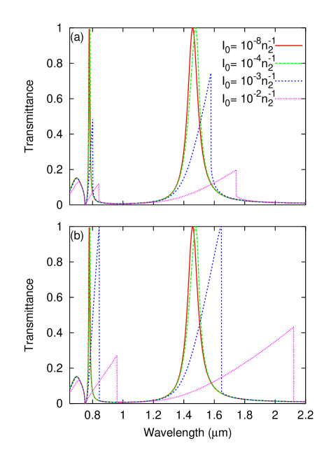
Fig. 2(a) renders the transmittance (total transmitted flux divided by incident flux) versus wavelength, for different values of in units of . For the chosen parameters, in the linear regime (red curves in both panels (a) and (b)), the metallic grating presents two transmission resonances, appearing at m and m, very close to the period of the grating. These two peaks are representative of the two types of transmission resonances appearing in metallic gratings por99 ; col01 : i) slit waveguide modes in which the EM-fields are highly concentrated within the slits and ii) coupled surface plasmon polaritons (SPP) excited at the entrance and exit interfaces of the structure. In Fig. 2(a), the transmittance at a given wavelength has been obtained by considering the converged situation at a lower incident flux (for that particular wavelength) as the seed for the iterative scheme. As can be seen, as the incident flux is increased, the peaks shift to larger wavelengths and their magnitude decreases. In Fig. 2(b) we represent the same quantity, transmittance versus wavelength, for the same structure, but for decreasing incident fluxes. For a given wavelength, the flux is first increased up to , which is a representative value of a “high-flux” situation, and then decreased slowly to the value , using as seed for the iterative procedure the converged solution obtained for a higher flux. Remarkably, the transmission spectra differ for increasing and decreasing fluxes, which is a clear manifestation of optical bistability. Besides, for decreasing incident flux, the transmission spectra depends on the initial incident flux . In particular, in Fig. 2(b) the transmittance peaks for incident flux 10 would increase (and even reach unity) for larger values of .

Optical bistability is better analyzed considering the situation for a fixed wavelength. In Fig. 3(a), we show the transmitted flux as a function of for , which is the typical wavelength used in telecommunications (and slightly larger than the wavelength of the waveguide mode in the structure under consideration in this paper). A clear bistable loop is observed at a range of incident fluxes. When increasing the incident flux (full line in Fig. 3(a)), the transmitted flux increases. At a certain incident flux (for this particular case around ), the transmitted flux jumps to a higher value in a discontinuous manner. By contrast, the system has a different behavior when the incident flux is decreased. The system, now in a high transmittance situation, instead of jumping back to low transmitted flux, follows the upper branch in Fig. 3(a). In this system, where losses are not included, the upper branch finishes when the ratio between the transmitted flux and the incident flux reaches the unity. Then, the transmitted flux jumps discontinuously to a lower value. The presence of a narrow bistability region such as the one illustrated in Fig. 3(a) is an interesting situation for device applications, as small changes in the incident flux would imply significant changes in the transmitted flux.
Optical bistability is also obtained associated with the transmission resonance linked to the excitation of two coupled SPPs. In Fig. 3(b), we show the bistable loop obtained for a wavelength of m, just slightly larger than the period of the grating. The bistable region is wider than in the previous case, mainly due to the higher incident flux needed to jump to the upper branch when increasing the incident flux.
It is interesting to note here the similarities between the curves rendered in Fig. 3 for increasing and the measurements of light tunneling through individual pinholes in a granular gold film covered with a layer of a nonlinear material (polydiacetylene) reported in Ref. 21. These results were explained in terms of a “photon blockade” phenomenon. In our system, if the thickness of the metal film is large enough, the spectral separation between different slit waveguide modes is strongly reduced. Then, as the incident flux is increased, several resonances can participate in the transmission process resulting in a staircase behaviour of the transmitted flux versus the incident one, as can be seen in the inset of Fig. 3a for a metallic grating of m. This behaviour is a clear signal of the existence of “photon blockade” phenomena in the system analyzed here. We believe that the structure proposed in this paper (array of subwavelength apertures) is an alternative that could allow the investigation of this interesting phenomenon in a more controlled way.
We find that there are two characteristic EM-field patterns associated, respectively, with the lower and the upper branch of the bistability loop. At a given wavelength, the field pattern within the slits for the lower branch corresponds approximately to the field pattern obtained in the linear response calculation. Even in this case, the lower branch presents, close to its instability, non-linearities. However, these non-linearities are associated more to the change in the average dielectric constant inside the slit (via Eq.( 1)) than to changes in the EM-field profile. The upper branch presents a different field pattern which is, essentially, the one associated to the closest transmission resonance located at a shorter wavelengthnote_smaller .

Let us now study how the width of the bistability region depends on the wavelength. In Fig. 4 we show the incident flux corresponding to the start and the end of this region as a function of the wavelength. For wavelengths in the interval between m and m, bistability is related to the shift to larger wavelengths of the coupled SPP resonance. The width of the bistability region increases dramatically with the wavelength. We arbitrarily terminate the curves at =1.3m, since the incident flux needed to jump to the upper branch, which corresponds to the end of the bistability region, becomes so high that our model is not valid any longer. For wavelengths larger than m, the first bistability region is related to the shift to larger wavelengths of the slit waveguide mode appearing approximately at m at low incident flux. Notice that the bistability regions do not start exactly at the position of the linear-response transmission resonances. As an approximate phenomenological rule we have found that bistability regions start at slightly larger wavelengths, for which transmittance is of the order of of the transmission peak.
Given available fluxes and Kerr nonlinear media, optical bistability should be experimentally accessible already. For instance, some polymers can present a Kerr coefficient up to . These values would imply incident fluxes of the order of W/cm2 for observing bistability, for the parameters chosen in this article. For higher ratios between the lattice parameter and the slit, given that the energy flux inside the slits increases as , bistability should occur for even smaller values of the incident flux.
In summary, we have analyzed the optical response of a metallic grating with subwavelength slits containing Kerr nonlinear media by means of a self-consistent method. The nonlinear response induces changes in the transmission spectra, with shifts of the transmission peaks to larger wavelengths. In addition, transmission spectra differ for increasing and decreasing intensity. An important result is the observation of optical bistability for certain ranges of wavelength and incident flux. The levels of optical power needed for observing these effects are achievable for typical Kerr nonlinear materials.
JAP gratefully acknowledges financial support from the Ramón y Cajal Program from the Ministerio de Ciencia y Tecnología of Spain. Financial support by the Spanish MCyT under contracts MAT2002-01534 and MAT2002-00139 and by EU-STREP project “Surface Plasmon Photonics” is gratefully acknowledged.
References
- (1) S. John and N. Akozbek, Phys. Rev. Lett. 71, 1168 (1993).
- (2) M. Scalora, J.P. Dowling, C.M. Bowden, and M.J. Bloemer, Phys. Rev. Lett. 73, 1368 (1994).
- (3) J. W. Fleischer, M. Segev, N.K. Efremidis, and D.N. Christodoulides, Nature 422, 147 (2003).
- (4) E. Centeno and D. Felbacq, Phys. Rev. B 62, 7683(R) (2000).
- (5) M. Soljacić, M. Ibanescu, S. G. Johnson, Y. Fink, and J. D. Joannopoulos, Phys. Rev. E 66, 055601(R) (2002).
- (6) M. Soljacić, C. Luo, J. D. Joannopoulos, and S. Fan, Opt. Lett. 28, 637 (2003).
- (7) M. F. Yanik, S. Fan, and M. Soljacić, Appl. Phys. Lett. 83, 2739 (2003).
- (8) T. W. Ebbesen, H. J. Lezec, H. F. Ghaemi, T. Thio, and P. A. Wolff, Nature (London) 391, 667 (1998).
- (9) A. Krishnan, T.Thio, T.J. Kim, H.J. Lezec, T.W. Ebbesen, P.A. Wolff, J. Pendry, L. Martin-Moreno, and F.J. Garcia-Vidal, Opt. Comm. 200, 1 (2001).
- (10) I. I. Smolyaninov, A. V. Zayats, A. Stanishevsky, and C. C. Davis, Phys. Rev. B 66, 205414 (2002).
- (11) A. M. Dykhne, A. K. Sarychev, and V. M. Shalaev, Phys. Rev. B 67, 195402 (2003).
- (12) U. Schröter and D. Heitmann, Phys. Rev. B 58, 15 419 (1998).
- (13) J. A. Porto, F. J. García-Vidal, and J. B. Pendry, Phys. Rev. Lett. 83, 2845 (1999).
- (14) H. E. Went, A. P. Hibbins, J. R. Sambles, C. R. Lawrence, and A. P. Crick, Appl. Phys. Lett 77, 2789 (2000).
- (15) S. Collin, F. Pardo, R. Tessier, and J. L. Pelouard, Phys. Rev. B 63, 033107 (2001).
- (16) A. Barbara, P. Quémerais, E. Bustarret, and T. Lopez-Rios, Phys. Rev. B 66, 161403(R) (2002).
- (17) H.J. Lezec, A. Degiron, E. Devaux, R.A. Linke, L. Martin-Moreno, F.J. Garcia-Vidal, and T.W. Ebbesen, Science 297, 820 (2002).
- (18) F. J. García-Vidal and L. Martín-Moreno, Phys. Rev. B 66, 155412 (2002).
- (19) L. Martin-Moreno, F.J. Garcia-Vidal, H.J. Lezec, A. Degiron, and T.W. Ebbesen, Phys. Rev. Lett. 90, 167401 (2003).
- (20) F.J. Garcia-Vidal, H.J. Lezec, T.W. Ebbesen, and L. Martin-Moreno, Phys. Rev. Lett. 90, 213901 (2003).
- (21) I.I. Smolyaninov, A.V. Zayats, A. Gungor, and C.C. Davis, Phys. Rev. Lett. 88, 187402 (2002).
- (22) This occurs for . For , the field pattern would be the corresponding to the closest transmission resonance at larger wavelengths.