Spin separation in cyclotron motion
Abstract
Charged carriers with different spin states are spatially separated in a two-dimensional hole gas. Due to strong spin-orbit interaction holes at the Fermi energy have different momenta for two possible spin states travelling in the same direction and, correspondingly, different cyclotron orbits in a weak magnetic field. Two point contacts, acting as a monochromatic source of ballistic holes and a narrow detector in the magnetic focusing geometry are demonstrated to work as a tunable spin filter.
pacs:
PACS numbers: 72.25.-b, 73.23.Ad, 71.70.Ej, 85.75.-dThe ability to manipulate the spin of charge carriers in a controllable fashion is a central issue in the rapidly developing field of spintronicswolf01 , as well as in the development of spin-based devices for quantum information processingdivincenzo95 . Electrical injection of spin-polarized currents has proven to be a formidable challenge. To date, spin polarized currents have been generated by using either ferromagnetic materials as injectorsfiederling99 ; ohno99 ; jedema02 ; hammar02 , or by exploiting the large spin splitting of electron energy levels in strong magnetic fieldsfolk03 ; hanson03 . Here we realize a solid-state analog of the Stern-Gerlach experiment in atomic physicsgerlach22 , with spin-orbit interactions playing the role of the gradient of magnetic field. We achieve spatial separation of spins and bipolar spin filtering using cyclotron motion in a weak magnetic field.
Our approach is to use intrinsic spin-orbit (SO) interactions existing in low-dimensional systems. It has long been appreciated that such interactions can be interpreted as an effective momentum-dependent magnetic field that influences spin of charge carriersrashba60 . More recently, it has been recognizedaronov93 ; loss90 ; aharonov84 ; aleiner01a that SO interactions can be also viewed as an effective orbital magnetic field with an opposite sign for different spin orientations. Now, assume that two different magnetic fields affect orbital motion of charge carriers with two distinct spins. Here, is the perpendicular external magnetic field and is the spin-orbital effective field characteristic for cyclotron motion. Then, charge carriers move along the cyclotron orbit with spin-dependent radius , where and are the Fermi momentum and energy, and is the charge of carriers. A spin-dependent has been observed in commensurability oscillationslu98 . Our goal here is to use spin-dependence of for spatial separation of carriers with distinct spins. To do this, we use magnetic focusingsharvin65 ; tsoi75 ; houten89 that we show to be spin-dependent as a result of SO interactions. In the magnetic focusing configuration, charge carriers are injected in the two-dimensional gas through the injector quantum point contact (QPC), propagate along the orbits defined by , and are detected by the detector QPC. By adjusting , we select the spin of charge carriers that reach the detector. Tuning is possible by either changing , changing electron density with electrostatic gates (, where is the carrier density), or changing by adjusting external electric fields miller02 ; papadakis02 .
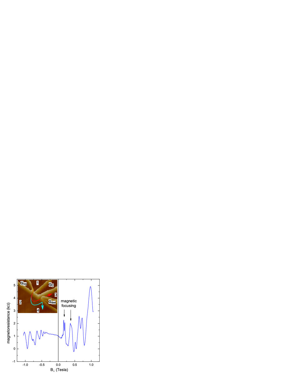
To demonstrate spatial separation of spins experimentally we fabricated several devices in the magnetic focusing geometry from two dimensional hole gas (2DHG), see inset in Fig. 1. The structure is formed using atomic force microscopy local anodic oxidation technique (AFM LAO)snow94 ; held97 ; rokhinson02 . Oxide lines separate the 2DHG underneath by forming mV potential barriers. A specially designed heterostructure is grown by MBE on [113]A GaAs. Despite very close proximity to the surface (350Å), the 2DHG has an exceptionally high mobility Vs/cm2 and relatively low hole density cm-2. The device consists of two QPCs separated by a central gate. Potential in the point contacts can be controlled separately by two gates and , or by the central gate . In our experiments the central gate was kept at V and V were applied to the gates and . Asymmetric biasing of point contacts provides sharper confining potential and reduces the distance between the two potential minima by m.
Magnetic focusing manifests itself as equidistant peaks in magnetoresistance for only one direction of . is measured by applying small current through the injector QPC while monitoring voltage across the detector QPC, see inset in Fig. 1. At cyclotron motion forces carriers away from the detector. Than, only 2DHG contributes to , which has almost no -dependence at low fields and shows Shubnikov–de Haas oscillations at T. For several peaks due to magnetic focusing are observed. Peaks separation T is consistent with the expected value for the lithographical distance between the injector and detector QPCs m. The data is symmetric upon exchange of the injector and detector and simultaneous reversal of the magnetic field direction.
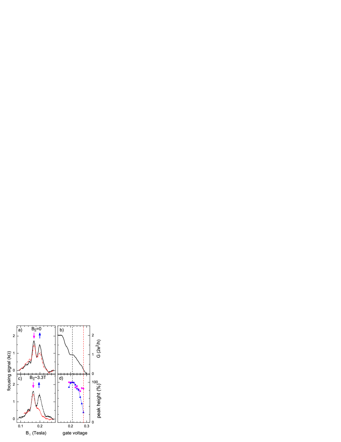
The first focusing peak is a doublet consisting of two peaks separated by mT. These peaks are the sharpest when both QPCs are gated to pass exactly one spin-degenerate mode (within the k conductance plateau in the QPC characteristic, Fig. 2b). Peaks in a doublet have approximately the same height.
A QPC can be used as a spin filter for one spin polarization if spin degeneracy is lifted by Zeeman splitting of energy levels in a strong magnetic fieldpotok02 . We apply an in-plane field , which has little effect on the cyclotron motion of holes but acts on their spin degrees of freedom. At T there is a pronounced step at in conductance vs gate voltage characteristic in both QPCs, see Fig. 2b. The appearance of this step means that Zeeman energy exceeds both the broadening of the transverse quantized energy levels of the QPC and the temperature. Then, for only holes with one spin polarization are allowed to pass through the point contact. Experimentspotok02 with electrons had shown reduction of the height of the focusing peaks by 50% due to spin filtering, when conductance of one QPC was tuned below and conductance of the other QPC was maintained at .
We use the spin filtering by QPCs at high to probe the spin states which correspond to the first focusing peak doublet. As the conductance of the injector QPC is reduced below , the height of the high-field peak in the doublet reduces while the height of the low-field peak remains almost the same, see Fig. 2c,d. When conductance of the injector QPC is , the high-field peak almost vanishes in a striking contract to the electron case. Similarly, the high-field peak vanishes if detector acts as a spin filter while injector is tuned to accept both spin polarizations. In contrast, at zero peaks relative strength does not change significantly as the injector conductance is decreased, see Fig. 2a. A small suppression of the high-field peak at can be attributed to a partial lifting of the spin degeneracy in a non-zero focusing field T. Therefore, we conclude that the two peaks within the doublet correspond to the two spin states of the holes. The peak spacing of 36 mT means that focusing points for the two spin states are nm apart.
In order to explain the effect qualitatively, we assume that charge carriers in GaAs quantum well are characterized by the isotropic kinetic energy and the Dresselhaus spin-orbit interaction, so that the Hamiltonian can be written as altshuler81 , where is the effective mass, is the electron momentum, are the Pauli matrices (), and is the spin-orbit parameter. For simplicity, we neglect anisotropy of the effective mass that do not change the qualitative picture. In the semiclassical description, appropriate for the range of magnetic fields used for the focusing, the motion is described by simple equations
| (1) |
where , and are the charge carrier coordinate, velocity and energy for the two spin projections. This description implies that carrier wavelength is smaller than the cyclotron radius, and that jumps between orbits with different spin projections are absent, i.e. . Eqs. (1) show that the charge carrier with energy is characterized by the spin-dependent trajectory: momentum , coordinate and cyclotron frequency . The solution to these equations is
| (2) |
Thus, as discussed in the introduction, the cyclotron motion is characterized by the spin-dependent field . Using the semiclassical limit of the quantum description, one obtains the identical resultsbychkov84a .
In the focusing configuration QPCs are used as monochromatic point sources. Holes, injected in the direction perpendicular to the two-dimensional hole gas boundary, can reach the detector directly or after specular reflections from the boundary. As follows from Eqs. (2), for each of the two spin projections there is a characteristic magnetic field such that the point contact separation is twice the cyclotron radius for a given spin, , . The first focusing peak occurs at
| (3) |
The magnitude of can be calculated directly from the peak splitting eVs/m. A larger value of eVs/m was extracted from the splitting of cyclotron resonance at 3 times higher hole concentrationstormer83 . For electrons, a much smaller value eVs/m characterizes the combined spin-cyclotron resonancestein83 . We note that Eq. (3) is more general than the Eqs. (2). The coefficient essentially describes the separation in momentum space of the two parts of the Fermi surface which correspond to , and includes contributions of various spin-orbit terms in the 2D hole gas. Analysis of the second and higher focusing peaks is complicated by mixing of spin states due to reflections from the boundary. If carriers necessarily undergo transitions between and parts of the Fermi surface upon reflections, no splitting of the second and other even focusing peaks is expected usaj04 .
We now discuss spin states and their filtering by QPCs in more detail. In the presence of SO interactions carriers are characterized by the projection of their spin on the total magnetic field, which is comprised of the external magnetic field and the effective momentum-dependent SO field. In our devices, the characteristic energy of SO interactions meV is larger than the Zeeman energy, and the quantum states of the 2D holes are well characterized by the sign of the spin projection onto their momentum ( meV at 3.5 T, for [33] crystallographic direction). for these 2D states are different for different spin projection signs.
However, in a QPC the hole momentum decreases and even vanishes on the plateau, so that . In this case holes are characterized by their spin projection on the external magnetic field. Thus, they can be spin-filtered by gating the QPC to . A hole, leaving injector in a certain spin state, will enter detector with the same spin orientation as long as 1D spin states in both QPCs adiabatically evolve into -projection states in the 2DHG, and spin evolution is adiabatic along the ballistic cyclotron trajectory.
The spin-dependent focusing field is proportional to the spin-orbit constant and does not depend on the cyclotron frequency . At the same time, the spin-dependent cyclotron frequency in Eq. 2 is proportional to both and . Thus, the effective magnetic field is itself proportional to . This effect differs from the spin-dependent shift of the Aharonov-Bohm oscillations in the conductance of rings, where the additional spin-orbit flux and the Aharonov-Bohm flux are independent of each otheraronov93 . If Zeeman effect is taken into account, both and acquire additional dependence on , as well as on . However, in the present experimental setting the Zeeman splitting is small compared to the effects of SO interactions and is essential for filtering spins in the injector and detector QPCs only.
The phenomenon we report in this Letter is not restricted to holes in GaAs but is generic to any system with intrinsic spin-orbit interactions. We believe that exceptional quality two-dimensional hole systems provides novel opportunities for spin manipulation. In particular, it will be possible to realize other schemes of spin separation and filteringdatta90 ; khodas04 .
In conclusion, we developed a method to spatially separate spin currents in materials with intrinsic spin-orbit interactions by a weak magnetic field. This has been achieved in semiclassical cyclotron motion, where distinct spins are characterized by distinct cyclotron radii and frequencies. Thus the cyclotron motion can separate not only the particles with different masses but also particles with different spin-orbit parameters. We confirm the spatial separation of spins experimentally by selectively detecting spin-polarized currents.
Authors thank A. M. Finkelstein and G. F. Giuliani for enlightening discussion. The work was partially funded by DARPA and NSA/ARDA.
References
- (1) S. A. Wolf, D. D. Awschalom, R. A. Buhrman, J. M. Daughton, S. V. Molnar, M. L. Roukes, A. Y. Chtchelkanova, and D. M. Treger, Science 294, 1488 (2001).
- (2) P. D. DiVincenzo, Science 270, 255 (1995).
- (3) R. Fiederling, M. Keim, G. Reuscher, W. Ossau, G. Schmidt, A. Waag, and L. W. Molenkamp, Nature (London) 402, 787 (1999).
- (4) Y. Ohno, D. K. Young , B. Beschoten , F. Matsukura, H. Ohno, and D. D. Awschalom, Nature (London) 402, 790 (1999).
- (5) F. J. Jedema, H. B. Heersche, A. T. Filip, J. J. A. Baselmans, and B. J. V. Wees, Nature (London) 416, 713 (2002).
- (6) P. R. Hammar and M. Johnson, Phys. Rev. Lett. 88, 066806 (2002).
- (7) J. A. Folk, R. M. Potok, C. M. Marcus, and V. Umansky, Science 299, 679 (2003).
- (8) R. Hanson, B. Witkamp, L. M. K. Vandersypen, L. H. W. V. Beveren, J. M. Elzerman, and L. P. Kouwenhoven, Phys. Rev. Lett. 91, 196802 (2003), eprint cond-mat/0303139.
- (9) W. Gerlach and O. Stern, Zeitschrift für Physik 9, 349 (1922).
- (10) E. I. Rashba, Sov. Phys. Solid State 2, 1109 (1960).
- (11) A. G. Aronov and Y. B. Lyanda-Geller, Phys. Rev. Lett. 70, 343 (1993).
- (12) D. Loss, P. Goldbart, and A. V. Balatsky, Phys. Rev. Lett. 65, 1655 (1990).
- (13) Y. Aharonov and A. Casher, Phys. Rev. Lett. 53, 319 (1984).
- (14) I. L. Aleiner and V. I. Fal’ko, Phys. Rev. Lett. 87, 256801 (2001).
- (15) J. P. Lu, J. B. Yau, S. P. Shukla, M. Shayegan, L. Wissinger, U. Rössler, and R. Winkler, Phys. Rev. Lett. 81, 1282 (1998).
- (16) H. VanHouten, C. W. J. Beenakker, J. G. Williamson, M. E. I. Broekaart, P. H. M. VanLoosdrecht, B. J. VanWees, J. E. Mooij, C. T. Foxon, and J. J. Harris, Phys. Rev. B 39, 8556 (1989).
- (17) Y. V. Sharvin, Zh. Eksp. Teor. Fiz. 48, 984 (1965) [Sov. Phys. JETP 21, 655 (1965).
- (18) V. S. Tsoi, JETP Letters 22, 197 (1975).
- (19) J. B. Miller, D. M. Zumbuhl, C. M. Marcus, Y. B. Lyanda-Geller, D. Goldhaber-Gordon, K. Campman, and A. C. Gossard, Phys. Rev. Lett. 90, 076807 (2002).
- (20) S. J.Papadakis, E. P. DePoortere, H. C. Manoharan, J. B. Yau, M. Shayegan, and S. A. Lyon, Phys. Rev. B 65, 245312 (2002).
- (21) E. S. Snow and P. M. Campbell, Appl. Phys. Lett. 64, 1932 (1994).
- (22) R. Held, T. Heinzel, A. P. Studerus, K. Ensslin, and M. Holland, Appl. Phys. Lett. 71, 2689 (1997).
- (23) L. P. Rokhinson, D. C. Tsui, L. N. Pfeiffer, and K. W. West, Superlattices Microstruct. 32, 99 (2002), eprint cond-mat/0303011.
- (24) R. M. Potok, J. A. Folk, C. M. Marcus, and V. Umansky, Phys. Rev. Lett. 89, 266602 (2002).
- (25) B. L. Altshuler, A. G. Aronov, A. I. Larkin, and D. E. Khmelnitskii, Zh. Eksp. i Teor. Fiz., 81 768 (1981) [Sov. Phys. JETP 54, 411 (1981).
- (26) Y. A. Bychkov and E. I. Rashba, Pisma Zh. Eksp. Teor. Fiz. 39, 66 (1984) [JETP Lett. 39, 78 (1984).
- (27) H. L. Störmer, Z. Schlesinger, A. Chang, D. C. Tsui, A. C. Gossard, and W. Wiegmann, Phys. Rev. Lett. 51, 126 (1983).
- (28) D. Stein, K. v. Klitzing, and G. Weimann, Phys. Rev. Lett. 51, 130 (1983).
- (29) G. Usaj and C. A. Balseiro, Phys. Rev. B 70, 041301 (2004), eprint cond-mat/0405061.
- (30) S. Datta and B. Das, Appl. Phys. Lett. 56, 665 (1990).
- (31) M. Khodas, A. Shekhter, and A. Finkelstein, Phys. Rev. Lett. 92, 086602 (2004).