Shear band formation in granular media as a variational problem
Abstract
Strain in sheared dense granular material is often localized in a narrow region called shear band. Recent experiments in a modified Couette cell Fenistein2003a ; Fenistein2003b provided localized shear flow in the bulk away from the confining walls. The non-trivial shape of the shear band was measured as the function of the cell geometry. First we present a geometric argument for narrow shear bands which connects the function of their surface position with the shape in the bulk. Assuming a simple dissipation mechanism we show that the principle of minimum dissipation of energy provides a good description of the shape function. Furthermore, we discuss the possibility and behavior of shear bands which are detached from the free surface and are entirely covered in the bulk.
pacs:
45.70.Mg, 45.70.-n, 83.50.AxGranular media constitute an interesting field of research from the point of view of both basic science and application. The intrinsically nonlinear and dissipative nature of the interaction between the particles leads to a great deal of interesting phenomena including force networks, different kinds of instabilities, clustering, complex flow properties DryGranu98 ; Jaeger96 . One of the most apparent instabilities occurring in granular media is the formation of shear bands: At slow shear rate strain is not distributed throughout the sample but appears in a localized fashion along a rather narrow interface between two essentially unstrained parts. Shear-banding was the subject of various experimental and theoretical studies in the last few years DryGranu98 ; Mueth00 ; Hartley03 ; Thompson91 ; Torok00 ; Schwedes03 ; Veje99 and still presents significant difficulties for theoretical descriptions.
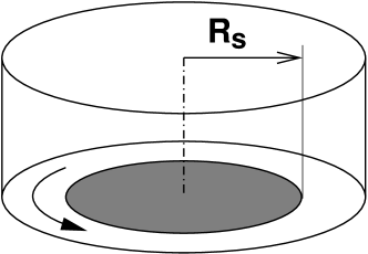
Recently universal geometrical properties of shear bands were discovered in a Couette geometry modified such that shear localization near boundaries was avoided Fenistein2003a ; Fenistein2003b . The experimental setup was a cylindrical container filled with grains up to height . The bottom was split into an outer ring rotating with the container wall, and a stationary disk of radius in the center (Fig. 1)111The experiments Fenistein2003a ; Fenistein2003b were performed both with “disk” geometry and with a split-bottomed Couette geometry, where an additional stationary inner cylinder is present. In this paper only the “disk” geometry is discussed.. Thus the outer and the inner part of the material were rotated relative to each other which created a shear band with cylindrical symmetry: It started at the perimeter of the stationary bottom disk and extended through the bulk up to the free surface. On the surface the angular velocity of the granular material as the function of the radius was measured. It follows to high accuracy an error function characterized by two parameters: the width and the center position of the shear zone. The width grows with increasing height while the radius gets smaller. Interestingly, the surface position proved to be very robust: It depends only on two length parameters and , but not on the particle properties nor on the shear rate. This is contrary to the width of the band, which is affected by the size and shape of the grains but is insensitive to changes of the slip radius . The fact that and depend on different control parameters suggests that the two quantities can be studied separately.
In this Letter we address the problem of the position of the shear band. By suitable choice e.g. of the particle size the width can be made arbitrarily small compared to and . This justifies to model the shear band as an infinitely thin layer that represents the boundary between two blocks of material within which no flow occurs. We derive the shape of the band from a variational principle. Note that optimization principle was applied already to shear band formation in a different context Torok00 .
Surface - bulk relation. In the experiments the position on the free surface was found Fenistein2003b to scale like
| (1) |
with for the experimentally accessible values of . It is much more difficult to measure the position of the shear band in the bulk, , for fixed and . Nonetheless, the experimental data clearly show that the bulk profile follows another form than , and the bulk radius at height depends also on the filling height (Fig. 2).
We show that the bulk profile is determined once the surface positions are given. Let us take a system with total height and find the position of the shear band at height . The subsystem above can be regarded as a smaller system with height and with slip radius at the bottom. Pressure and boundary conditions are the same, and the difference in the width is neglected in the narrow band approximation. We conclude that
| (2) |
Knowing the function thus allows to calculate the shape of the shear band throughout the whole system. Note, if the simple size scaling holds for the surface radius that depends only on (as it was found in Fenistein2003b ) then it follows immediately also for the bulk function due to Eq. (2):
| (3) |
Based on Eq. (2) an explicit functional form of the bulk profile can be obtained using the experimental fit function of :
| (4) |
The resulting curves for some filling heights are plotted in Fig. 2 using and the comparison with the experimental data shows very good agreement.

Variational principle. In order to describe the form of the shear band our idea is to apply the principle of least dissipation Onsager1931 (which is a common treatment of time-independent irreversible phenomena statphys ). Therefore we require a steady state flow that matches the outer constraints but provides the minimum rate of energy dissipation.
Applying this to the cylindrical geometry within the narrow band approximation the question of the shape is traced back to a variational problem among the functions (where and are kept fixed) with the condition while the other boundary at is free. The dissipation rate is given by the sliding velocity between the two sides times the shear stress integrated over the whole shear band. Up to a constant factor, the expression to be minimized is
| (5) |
This quantity represents not only the dissipation rate but also the mechanical torque that the rotating and stationary part of the system exert on each other. Therefore the least dissipation for this specific geometry is equivalent to the minimal torque which gives further justification of this approach: it is plausible that the yielding surface is established where the resistance against the outer constraint is the smallest, i.e. where the material is the weakest Torok00 .
Sliding model. For the shear stress in Eq. 5 we will use a very simple sliding model. The shear stress in the yielding surface is taken similar to the Coulomb friction between two solid bodies: It acts against the sliding direction, its magnitude is proportional to the normal pressure pressing the two sides against each other, but it is independent of the sliding velocity. We assume hydrostatic pressure i.e. proportional to the depth 222Here we ignore anisotropy effects.. Thus Janssen effect is neglected, which is naturally justified if H is smaller than the container width. In our dynamical situation, however, we expect that the applicability of the hydrostatic pressure can be extended even for larger filling heights: The shear band (due to many collisions and slip events) acts as a source of small vibrations in the whole system and can cause slight creep at the particle-wall contacts inhibiting the particles to keep their original anchoring position. Finally they transmit their load to the next particle below rather than to the side wall and therefore the whole weight will be carried by the bottom.
This sliding model leads to the variational problem
| (6) |
The solutions which minimize the integral have automatically the scaling property given by Eq. (3). The reason of this data collapse is that taking a times larger system (i.e. taking , , instead of , , ) changes the value of the integral only by a constant factor () thus it represents the same variational problem.
Numerical results. The function is discretized and the minimization is performed numerically based on genetic optimization: is varied randomly but only the changes that lower the value of the left hand side in Eq. (6) ,i.e., reduce the dissipation, are admitted. During the optimization the noise level is continuously decreased and the final state is regarded as one local minimum of the variational problem. The landscape where the minimum has to be found is simple (see later).

Results shown in Fig. (3) reproduce nicely the qualitative behavior found in the experiment: the concave shear bands appear in the bulk and build up a convex confining shape of the surface positions as the filling height is varied. The shear radii at a fixed bulk height and also at the top get smaller with increasing filling height.
The realistic bulk profiles provided by the principle of minimum dissipation can be interpreted easily. The benefit gained by having such a curved cylindrical shape (slimmer at the top) in place of a regular cylinder is twofold: First, the surface of the shear band can be reduced by letting the regular cylinder deform and by pulling the shape towards the center a bit at a fixed bottom radius, similarly to a soap membrane spanned between a ring and a plate where the plane of the ring is parallel to the plate. Second, smaller radius results in smaller sliding velocity (or thinking of minimizing the torque it represents smaller lever). Therefore one can roughly think of the bulk profiles shown in Fig. (3) as equilibrium situations where the reduction of the sliding velocity is counterbalanced by the increase in the surface due to going beyond the minimum surface.
The quantitative agreement with the experimental fit function (Eq. 1) is also surprisingly good given the crude assumptions we made and the fact that our model contains no free fit parameters. The difference of the theoretical and the experimental values of is less than % of .
We can more easily analyze the limit than in the experiment, where -values are limited by the container size and a power law fit to the data at low filling heights is not very precise. From our variational principle we find an exponent for small . In the region there is no clean power law any more and the effective exponent increases. In our model this seems to be due to a phase transition at about to a different shape of the shear band, which we discuss next.

What is the predicted behavior of the shear band for filling heights larger then those reported in Fenistein2003a ; Fenistein2003b ? For large enough the class of the “open” solutions discussed so far is replaced by a new type of solutions: The shear band, instead of running up to the free surface and having a circle on the top as its upper edge, closes forming a cupola-like shape (still with bottom radius ). In that case the material covered by the “closed” shear band is at rest while the material around and above (including the whole free surface) is rotating. Several “open” and “closed” profiles can be seen in Fig. (4b) obtained for various values of . Fig. (4a) shows the upper radius of the shear bands which is characteristic of the “open” solutions but becomes zero for the “closed” ones. For these cupola shapes 333The “closed” profiles appear in the integral of Eq. (6) in the way that the function becomes zero for . Therefore this region has no contribution to the dissipation and practically the integral is meant over the interval . a more relevant parameter is their heights in the center, plotted in Fig. (4c). For “open” profiles equals simply the system height.
Interesting is the behavior of the parameter . It is a monotonically decreasing function of the filling height once it is detached from , i.e. large filling heights press the shear band to the bottom. Solving the Euler-Lagrange equation for the variational problem neglecting terms of higher than first order in and taking the limit of one obtains
| (7) |
Fig. (4d) shows the numerical solution of : it is in excellent agreement with the approximate analytical solution. In the limit the material forms one solid block and the sliding occurs on the surface of the bottom disk.
The dependence of has the following reason: Larger corresponds to lower pressure and thus to smaller shear-resistance; therefore it is worth to raise the shear band into a cupola-shape even if its surface becomes larger than the disk at the bottom. Note, however, that stronger gravity would not affect the shape: It gives a larger pressure gradient but this constant factor has no impact on the variational problem. By contrast, increasing (or, alternatively, applying additional pressure at the surface) makes the relative pressure change smaller near the bottom which results in weaker uplifting “force”. This is why the cupola height approaches zero for large (respectively large pressure).

At intermediate (around ) there exists a small region of filling heights where the variational problem (Eq. 6) exhibits two local minima. The behavior of the local minima corresponds to a first order phase transition, where the two phases are the two types of shear band profile (Fig 5). Following the “closed” solution as is decreased its height grows till the top of the cupola reaches the surface at system height . At this point the “closed” solution becomes unstable, at the top runs suddenly to a non-zero value (Fig. 5a). Regarding the other direction (increasing ) the upper edge of the “open” shape is pulled towards the center then at height it shrinks to one point which is followed by a jump into a “closed” shape (discontinuity in see in Fig. 5b). The interval defines the region where two local minima exist, outside this region there is only one phase possible. Local minima are physically meaningful in the presence of a kinetic barrier. The latter can be provided by the difference between the static and dynamic friction coefficients, usually present in granular systems.
In this Letter we have presented a theoretical analysis of recent experiments [1,2] on shear band formation in granular media. We used the approximation of narrow shear bands. First we showed a geometric argument which related the position of the surface endpoints of the band to the bulk shape. We calculated the shape of shear bands from a variational principle and the results are in good agreement with the experiments. The theory provides with a number of predictions. i) There is a transition in the shape of the shear band as a function of the filling height : For low values of the shear band is an open curved cylinder which ends on the surface while for large a cupola is formed. ii) This transition is of the first order, accompanied by a hysteresis. iii) The height of the cupola is proportional to . These predictions should be experimentally accessible.
An interesting question we did not address in this Letter is the nucleation kinetics at the first order phase transition from open to closed shapes. It is conceivable that the finite width of the shear bands plays a role here. Further progress in this direction requires a continuum theory going beyond the narrow band approximation we used here.
We would like to thank to D. Fenistein and M. van Hecke for useful discussions. Partial support by grant OTKA T035028 and by the German-Hungarian Cooperation Fund is acknowledged.
References
- (1) D. Fenistein and M. van Hecke, Nature 425, 256 (2003).
- (2) D. Fenistein, J. W. van de Meent and M. van Hecke, cond-mat/0310409 (2003).
- (3) Physics of Dry Granular Media, eds. H. J. Herrmann, J.-P. Hovi, S. Luding (Kluwer Academic Publishers, Dordrecht, 1998).
- (4) H. M. Jaeger, S. R. Nagel, R. P. Behringer, Rev. Mod. Phys. 68, 1259 (1996)
- (5) D. M. Mueth, G. F. Debregeas, G. S. Karczmar, P. J. Eng, S. R. Nagel and H. M. Jaeger, Nature 406, 385 (2000).
- (6) R. R. Hartley and R. P. Behringer, Nature 421, 928 (2003).
- (7) P. A. Thompson and G. S. Grest, Phys. Rev. Lett. 67, 1751 (1991).
- (8) J. Török, S. Krishnamurthy, J. Kertész and S. Roux, Phys. Rev. Lett. 84, 3851 (2000).
- (9) J. Schwedes, Gran. Mat. 5, 1 (2003).
- (10) C. Veje, D. Howell, and R. P. Behringer, Phys. Rev. Lett 82, 5241(1999).
- (11) M. van Hecke, private communication.
- (12) L. Onsager, Phys. Rev. 37, 405 (1931), Phys. Rev. 38 2265 (1931).
- (13) K. E. Reichl: A Modern Course in Statistical Physics 2nd ed. 1998. John Wiley, New York.