Interactions of vortices with rarefaction solitary waves in a Bose-Einstein condensate and their role in the decay of superfluid turbulence.
Abstract
There are several ways to create the vorticity-free solitary waves – rarefaction pulses – in condensates: by the process of strongly nonequilibrium condensate formation in a weakly interacting Bose gas, by creating local depletion of the condensate density by a laser beam, and by moving a small object with supercritical velocities. Perturbations created by such waves colliding with vortices are studied in the context of the Gross-Pitaevskii model. We find that the effect of the interactions consists of two competing mechanisms: the creation of vortex line as rarefaction waves acquire circulation in a vicinity of a vortex core and the loss of the vortex line to sound due to Kelvin waves that are generated on vortex lines by rarefaction pulses. When a vortex ring collides with a rarefaction wave, the ring either stabilises to a smaller ring after emitting sound through Kelvin wave radiation or the entire energy of the vortex ring is lost to sound if the radius of the ring is of the order of the healing length. We show that during the time evolution of a tangle of vortices, the interactions with rarefaction pulses provide an important dissipation mechanism enhancing the decay of superfluid turbulence.
pacs:
03.75.Lm, 05.45.-a, 67.40.Vs, 67.57.DeI Introduction
Low temperature superfluids and recently discovered dilute Bose-Einstein condensates are often modelled by the Gross-Pitaevskii equation (GP), which is a nonlinear Schröedinger equation on the one-particle wave function, . This equation provides a simple framework for study many fundamental hydrodynamical properties of condensates. In particular, vortex-sound interactions in condensates are receiving increasing attention over last couple of years vinen1 ; leadbeater1 ; br9 ; berloff ; vinen2 ; leadbeater2 . It has been suggested that the emission of sound by vortex reconnections and vortex motion is the only active dissipation mechanism responsible for the decay of superfluid turbulence. The decay of superfluid turbulence via Kelvin wave radiation and vortex reconnections was studied in the framework of the GP equation leadbeater2 . In this study the collision of two small vortex rings were analysed and the loss of the vortex line due to reconnections and Kelvin wave radiation was numerically evaluated.
The goal of this paper is to consider the effect of the vorticity-free solitary waves that together with vortices are created in Bose-Einstein condensates either during the self-evolution of a Bose gas from a strongly nonequilibrium initial state or evolved from local density depletions of a condensate. We show that the interactions with such waves trigger the loss of the vortex line via Kelvin wave radiation and that these interactions enhance the dissipation of the vortex tangle.
We write the GP equation in dimensionless form as
| (1) |
in dimensionless variables such that the unit of length corresponds to the healing length , the speed of sound is , and the density at infinity is . The numerical integration was performed using a finite difference scheme. The faces of the computational box were open to allow sound waves to escape; this is achieved numerically by applying the Raymond-Kuo technique rk . In the turbulence simulations the periodic boundary conditions were used to conserve the total number of particles in the system.
In a seminal paper, Jones and Roberts jr numerically integrated the GP equation (1) and determined the entire sequence of solitary wave solutions of the GP equation, such as vortex rings, vortex pairs, and finite amplitude sound waves named rarefaction pulses. They showed the location of the sequence on the momentum, , energy, , plane. In three dimensions they found two branches meeting at a cusp where and assume their minimum values, and . As on each branch, . On the lower branch the solutions are asymptotic to large vortex rings.
As and decrease from infinity along the lower branch, the solutions begin to lose their similarity to large vortex rings. Eventually, for a momentum slightly greater than , they lose their vorticity ( loses its zero), and thereafter the solitary solutions may better be described as ‘rarefaction waves’. The upper branch consists entirely of these and, as on this branch, the solutions asymptotically approach the rational soliton solution of the Kadomtsev-Petviashvili Type I equation.
The Jones-Roberts (JR) solitons are the only known disturbances that propagate with a constant velocity. Notice, however, that there many other waves that change their velocity and shape during their motion. For instance, a strong perturbation of a rarefaction pulse on the upper branch of the dispersion curve causes it to collapse onto the lower branch and become a vortex ring. During its transition the wave looses its energy and momentum and the minimum of its density decreases gradually before it reaches zero. In the next stage of the evolution the wave becomes a non-axisymmetric ring which radius increases until it reaches an axisymmetric solitary state on the lower branch of JR dispersion curve. All these intermediate time snapshots of the wavefunction of the condensate have higher energy than any solitary wave on the lower branch below the final axisymmetric vortex ring state although they may have the same minima of the density in the transition. In what follows we reserve the term “rarefaction pulse” or “rarefaction wave” to describe a finite amplitude sound wave which is a JR solitary wave. The scenario just described illustrates a typical mechanism in which the vortex line length may be created and increased as the result of perturbations of rarefaction pulses. In pade we have also considered a creation of vortex rings as a result of energy and momentum transfer between two interacting rarefaction pulses. But given a complex tangle of interacting vortices we expect that the loss of the vortex line length will dominate its creation to account for the experimentally observed decay of superfluid turbulence.
In pade we have developed an algorithm for finding approximations to the JR solitary wave solutions with the correct asymptotic behaviour at infinity. An axisymmetric solitary wave moving with the velocity along the axis is accurately approximated by where
| (2) |
where and the dipole moment can be determined from the series expansion and are functions of . Also in (2), , , and . Notice, that (2) represents a vortex ring as well as a vorticity-free rarefaction pulse depending on . If , then (2) represents a vortex ring as the power series expansion around zero shows; if , then (2) gives an approximation of a rarefaction pulse, and is a borderline case, such that the solitary wave has a single zero of the wavefunction and, therefore, can be called a point defect. These approximations can be used as initial conditions in the numerical simulation that study interactions, when the initial state is prepared by multiplying the wavefunctions of the distant individual solitary waves. Without an accurate starting point in numerical calculations it would be impossible to separate clearly the effect of interactions from the evolution of each solitary wave by itself as it settled down from a poor initial guess.
II Creation of rarefaction pulses in condensates
Here we study the excitations created by the collisions between rarefaction pulses and vortices and the effect these collision have on the evolution of vortex line length in a regime of superfluid turbulence with a tangle of vortices. We start by describing three typical scenario in which a large amount of rarefaction pulses is created, so that their collisions with vortices do become significant. The process of strongly nonequilibrium BEC formation in a macroscopically large uniform weakly interacting Bose gas was elucidated in svist using numerical integration of the GP equation. As the system evolves from weakly turbulent state to state of strong turbulence, the phases of the complex amplitudes of the wave field become strongly correlated and the period of their oscillations become comparable with the evolution times of the occupation numbers. This signifies that the quasicondensate is formed with appearance of a well-defined tangle of quantized vortices and localized vorticity-free solitary structures such as rarefaction pulses manifesting the start of the final stage in the Bose gas evolution: the decay of superfluid turbulence. The right panel of Fig. 5 presented in svist shows a single vortex ring surrounded by many rarefaction pulses as a result of the turbulent decay of the initial vortex tangle, which also implies that many more rarefaction pulses were present at the beginning of the decay.
Next we describe how the JR solitons and in particular rarefaction pulses can be created in Bose-Einstein condensates. It is generally believed that to create vortices it is necessary to transmit angular momentum by rotationally stirring the condensate with a laser beam. In bubble we demonstrated that the collapse of a stationary spherically symmetric bubble can lead to the vortex nucleation. After the condensate fills the cavity, it begins to expand with growing density oscillations. These ’dips’ of the density are themselves unstable and the development of this instability leads to the creation of localized disturbances: vortex rings and rarefaction pulses.
Similarly, the evolution of a depletion of the condensate by laser beam after the laser was turned off may lead to creation of JR solitons. Notice, that there is no need to add angular momentum or deplete the density of the condensate to zero. We demonstrate this by considering a depletion of the condensate, such that the wavefunction of the condensate just before the laser is switched off is given by
| (3) |
This density depletion roughly corresponds to the experiments in the sodium condensates, see for instance raman , with the healing length and the Gaussian beam waist of more than . The oblate spheroidal form of the depletion (3) would be formed if such a laser beam was guided in the condensate in a short straight streak of the length of about .
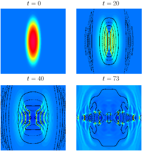
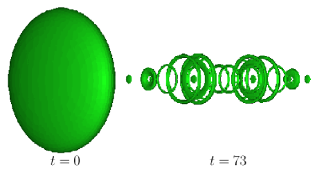
We integrated the GP equation (1) using (3) as our initial field in the box of the volume . The faces of the computational box were open to allow sound waves to escape. Fig. 1 shows the time snapshots of the density cross-sections for . Twelve vortex rings of various radii and four rarefaction pulses moving outward from the center of the depletion are clearly seen at snapshot. Fig.2 gives the isoplots of the density at . Rarefaction pulses are seen as small oblate spheroids.
The nucleation of vortices in a uniform condensate has been linked to critical velocities of the flow frisch ; br7 ; br8 . It has also been pointed out rica that a moving object of a size comparable with the healing length generates rarefaction pulses rather than vortex rings when the velocity on the surface of this object exceeds the local speed of sound. Therefore, it is possible to generate the rarefaction pulses by guiding small objects with supercritical velocities through the condensate.
III Collisions with a straight line vortex
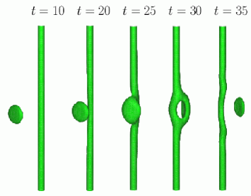
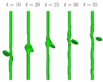
In our first example we consider a collision between a rarefaction pulse and the straight-line vortex of unit winding number. The rarefaction pulse is moving with a constant self-induced velocity and belongs to the lower branch of the JR dispersion curve. The sequence of density isosurface plots illustrating the collision for two impact angles ( and ) is shown in Fig. 3. Initially the center of the rarefaction pulse is 20 (Fig. 3(a)) or 10 (Fig. 3(b)) healing lengths apart from the axis of the vortex. During the collision the rarefaction pulse creates a distortion on the vortex line by exciting two Kelvin wave packets. In the close vicinity of the vortex line, the rarefaction pulse acquired vorticity it previously did not have and became a vortex ring (Fig. 3(a) at and and Fig. 3(b) at ), so we would expect that the result of the collision is similar to what was found in leadbeater2 for collisions of large vortex rings with small rings.
The dispersion relationship for Kelvin wave in the GP model in the limit is roberts02
| (4) |
which gives a group velocity of the Kelvin wave packet as
| (5) |
where is the dominating wavelength. Our calculations show that healing lengths and (), where is the speed of sound) which fits (5) quite well. This result also agrees (when different scaling of the GP equation is taken into account) with the wavelength of the excited Kelvin wave during the vortex reconnections in leadbeater2 .
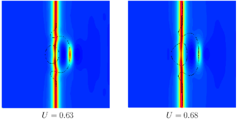
The collision with a rarefaction pulse from the upper branch of the JR dispersion curve excites a Kelvin wave packet of a similar central wavelength. Fig. 4 shows the contour plots of the density cross-sections of two such collisions for two different rarefaction pulses that belong to lower (left panel) and upper (right panel) branches of the JR dispersion curve. The wavelength of the created excitation is best seen by the intersections of zeros of real and imaginary parts of the wavefunction shown by solid and dashed lines correspondingly. Similarly, a collision with an offset generates a Kelvin wave packet of approximately the same dominating wavelength but a smaller amplitude.
We can estimate the amplitude of the Kelvin wave generated by a distant rarefaction wave by reducing the problem to two dimensions. We shall assume that initially the straight line vortex is positioned at and the rarefaction wave is moving in the positive direction along with . Under these assumptions, the wavelength of the perturbation along the vortex line is much larger than its amplitude, , (the maximum displacement of the vortex center from the origin in plane), therefore, we can assume that the and components of the force exerted by a rarefaction wave on the vortex dominate the component (in other words, the vortex may be considered as rigid). Also, if the incident angle of the rarefaction pulse and the direction of the vortex axis is nonzero, the amplitude calculated below would have to be multiplied by the cosine of this angle. In plane the vortex is advected by the rarefaction pulse, so that it instantaneous velocity coincides, to the leading order, with the velocity of the rarefaction pulse at the vortex location. The center of the rarefaction pulse is moving with the self-induced velocity, and is advected by the vortex. The motion of the vortex and of the rarefaction pulse is, therefore, given by the system of the coupled ordinary differential equations
| (6) | |||||
where and are the positions of the centres of the rarefaction pulse and the vortex, correspondingly, at time . and are the velocity components induced by the rarefaction pulse on the vortex given by and , where is the phase of the wavefunction , so that
| (7) |
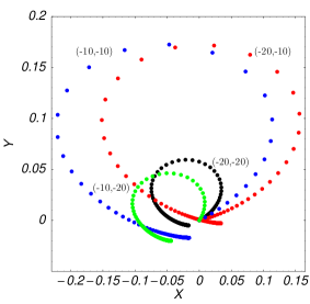
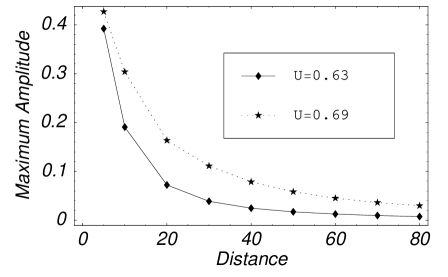
where the real, , and imaginary, , parts of are approximated by (2). The initial conditions are given by and . Fig. 5 shows the trajectories of the vortex for and and . It is clear from the figure, that the maximal amplitude of the displacement, , does not depend strongly on , but on . Fig. 6 plots as a function of for two rarefaction pulses that belong to the lower () and upper () branches of the JR dispersion curve. For large offsets, , () the maximum amplitude, , decays exponentially with , so that for and for .
IV Collisions with a vortex ring
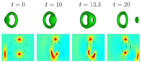
Next we consider the collision of a rarefaction pulse with a vortex ring. As in the previous cases, such a collision excites Kelvin wave with release of sound energy. Fig. 7 illustrates the time snapshots of the collision between the vortex ring of radius moving along the axis and the rarefaction pulse moving along the line . The total vortex line is dramatically increased at time (from the line length to ) due to the rarefaction pulse being transformed into a small vortex ring during a short time interval, . After that the ring loses its energy to Kelvin wave radiation and stabilises to axisymmetric vortex ring of slightly smaller radius at , so that the total loss of the vortex line is about . The length of the vortex line does not change for . We repeated the calculations for the rarefaction pulse from the upper branch of the JR dispersion curve and found that the ring stabilises after losing of its length. These results may seem to contradict the findings of leadbeater2 , where the length of the vortex line continues to decay after the collision. The calculations of leadbeater2 were done in computational box with periodic boundaries, so the sound waves generated during the reconnections of a large ring with a small ring continue to excite Kelvin waves on the vortex line with a continuous loss of the vortex line to sound radiation. The rate of the decay of the vortex line in this case should depend on the size of the computational box. In our calculations the faces of the computational box were open to allow sound waves to escape rk , which allowed us to compute the effect of a single collision with the finite amplitude sound wave.
For very small vortex rings () the collision with a rarefaction pulse causes all the energy and momentum to be converted into sound waves with a complete loss of the vortex line.
V Decay of a vortex tangle
Next, we estimate the effect that the interactions with rarefaction pulses have on a vortex tangle. This time we perform the simulations similar to those of kivotides ; leadbeater2 , in which the vortex tangle was created by four colliding rings in a periodic box. But in our simulations we regulate the initial amount of sound waves in our computational box by introducing them as randomly oriented rarefaction waves in addition to the vortex rings.
For simplicity we shall assume that all sound waves initially consist of three types of rarefaction pulses moving in random directions. The approximations to these solitary waves, that were developed in pade , become very useful in the construction of our initial conditions. If the rarefaction pulse given by (2) is rotated by angle to the axis in the plane and by angle to the axis in the plane, then its wavefunction is given by where , , and . The angles of rotation and as well as the center of the rarefaction pulse are chosen randomly.
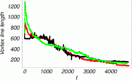
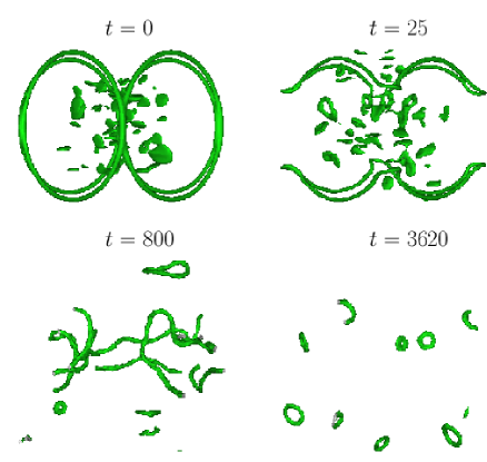
Our calculations were performed in a periodic box with volume, , which is divided by grid points with a spacing . The numerical scheme is 4th order globally accurate with 4th order Runge-Kutta time integration with the time step . A grid spacing of together with the time step was also used to test the accuracy of the numerical method. Initially there are four vortex rings of the radius centered at and that are moving towards the center of the box. rarefaction pulses are distributed randomly in the internal half of the box away from the vortices. The results for the dynamics of the vortex line length for three sets of computations with and are plotted in Fig. 8. The density isosurfaces plots for are given in Fig. 9. In the case of nonzero number of rarefaction pulses there is a rapid initial growth of the length of the vortex line due to the evolution of some of the rarefaction pulses into small vortex rings as the result of the energy transfer among them pade . Consequently, the length of the vortex line shows the balance between vortices being created and vortex line being destroyed due to reconnections and Kelvin wave radiation. Our simulations show that apart from the initial growth of the vortex line in the simulations with initially, the dynamics for and is very similar for in the time interval . On the other hand, the case with is quite different. During the time interval , the decay of the vortex tangle is much faster than for two other runs. Whereas after it is the run with that shows a slower decay. We speculate that this can be best explained by the following. During the moderate times, the vortex line loss due to the excitations of the vortex line created by rarefaction pulses depends on how many rarefaction pulses survived as their energy is gradually being converted to high-frequency waves. The more of rarefaction pulses were present in the initial state, the longer at least some of them are present in the system, therefore, the state with shows a faster decay during the moderate times. At larger times, all of the rarefaction pulses are destroyed by the collisions and vortices live on the background of high-frequency waves that limit their mobility and reduce the number of reconnections which slows down the decay of the vortex line length, with the total energy carried by these high-frequency waves being higher for the simulations with initially.
For even larger times the situation is reversed one more time as reconnections are now infrequent and the main decay mechanism is through Kelvin wave radiation. Therefore, the rate of decay of vortex line is propotional to the amount of high-frequency waves (slowest decay for , fastest decay for .)
For Kelvin-wave cascade, where energy is transfered to a much shorter wavelengths with a cutoff below a critical wavelength, the vortex line density can be described by the Vinen equation vinen
| (8) |
where in our dimensionless units and is a dimensionless coefficient. More accurately is a weak (logarithmic) function of and of other parameters such as the Kelvin cutoff and temperature. The logarithmic dependence on can be easily obtained in the context of the local induction approximation. The presence of a large amount of rarefaction pulses changes this weak dependence on and the decay of the vortex line approaches an exponential decay instead:
| (9) |
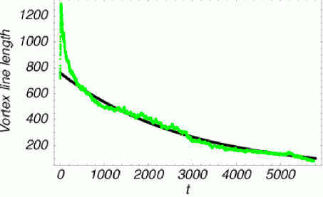
In Fig. 10 we plotted the curve (the solution of (9))
| (10) |
for and to illustrate the exponential decay of the vortex line length.
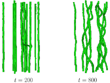
Finally, we note that the presence of rarefaction waves in a condensate with regular vortex lattices has destabilising effect and facilitates reconnections. If vortices are antiparallel, the Kelvin wave created on the filaments as the result of interaction with rarefaction waves facilitates the growth of the Crow instability br9 that leads to vortex reconnections that destroy a significant amount of vortex line (as we estimated in br9 , the minimum fractional line loss of the pair of antiparallel vortices that are initially the distance apart and perturbed by a wave of the wavenumber is about ). The interactions of the rarefaction waves with the lattice of parallel vortices (created, for instance, in rotating condensates) also destabilises the array and creates a tangle as Fig. 11 illustrates.
VI Conclusions
In summary, we established several mechanisms for creation of the rarefaction pulses in condensates. We have studied the effects of their interactions with straight line vortices, vortex rings and tangles of vortices. We showed that there are two competing mechanisms of these interactions. Firstly, the interactions of waves at close distances lead to the increase of the vortex line as the rarefaction pulses in the regions of lower density (in the vicinity of the vortex core or each other) may acquire circulation and become vortex rings. Secondly, rarefaction waves excite Kelvin waves on the vortex filaments causing a loss of the vortex line due to sound emission. At high vortex line densities our simulations suggest that the Kelvin wave radiation is enhanced by the presence of rarefaction pulses and this accounts for a dramatic increase in the rate of the decay of the vortex line length.
Acknowledgements.
The author acknowledges the support from the NSF grant DMS-0104288. The author is very greateful to Professor Paul Roberts for many discussions about the structure of rarefaction pulses and the importance of sound emission during her tenure at UCLA. The author is indebted to Professor Boris Svistunov for many useful comments about this manuscript.References
- (1) W.F. Vinen, Phys. Rev. B 64, 134520 (2001).
- (2) M. Leadbeater, T. Winiecki, D.C. Samuels, C.F. Barenghi and C.S. Adams, Phys. Rev. Letters 86 1410 (2001).
- (3) N.G. Berloff and P.H. Roberts, J. Phys. A: Math. Gen., 34 10057 (2001)
- (4) N.G. Berloff, Phys. Rev. B, 65 174518 (2002)
- (5) W.F. Vinen, M. Tsubota and A. Mitani, Phys. Rev. Letters 91, 135301 (2003).
- (6) M. Leadbeater, D.C. Samuels, C.F. Barenghi and C.S. Adams, Phys. Rev. A 67 015601 (2003).
- (7) G.W. Raymond and H.L. Kuo, Q. J. R. Meteorol. Soc. 110, 525 (1984)
- (8) C. A. Jones and P. H. Roberts, J. Phys. A: Gen. Phys. 15, 2599 (1982).
- (9) N. G. Berloff J. Phys.: Math. Gen. 37, 1617 (2004)
- (10) N.G. Berloff and B. V. Svistunov, Phys. Rev. A, 66, 013603 (2002)
- (11) N.G. Berloff and C.F.Barenghi, submitted to Phys. Rev. Lett, cond-mat/0401021.
- (12) C. Raman, M. Köhl, R. Onofrio et al., Phys. Rev. Lett, 83, 2502 (1999)
- (13) T. Frisch, Y. Pomeau and S. Rica, Phys. Rev. Lett., 69, 1644 (1992)
- (14) N. G. Berloff and P. H. Roberts, J. Phys.: Math. Gen. 33, 4025 (2000)
- (15) N.G. Berloff and P.H. Roberts, J. Phys. A: Math. Gen., 34 81 (2001)
- (16) Sergio Rica, private communications.
- (17) P. H. Roberts, Proc. R. Soc. Lond. A, 459, 597 (2002)
- (18) D. Kivotides, J.C. Vassilicos, D.C. Samuels and C.F. Barenghi, Phys. Rev. Letts., 86, 3080 (2001).
- (19) W.F. Vinen, Proc. R. Soc. London. Ser. A 242, 493 (1957)