Adaptable-radius, time-orbiting magnetic ring trap for Bose-Einstein condensates
Abstract
We theoretically investigate an adjustable-radius magnetic storage ring for laser-cooled and Bose-condensed atoms. Additionally, we discuss a novel time-dependent variant of this and other ring traps. Time-orbiting ring traps provide a high optical access method for spin-flip loss prevention near a storage ring’s circular magnetic field zero. Our scalable storage ring will allow one to probe the fundamental limits of condensate Sagnac interferometry.
type:
Letter to the EditorThe field of atom optics [1] has been transformed by laser cooling [2] and Bose-Einstein condensation (BEC) [3]. Prior to laser cooling, atoms could only be magnetically deflected by small angles, due to the relatively weak nature of the interaction and the large atomic velocities involved [4]. With the advent of laser cooling, atomic beams have been magnetically deflected by much larger angles [5], and cold atomic clouds have been magnetically reflected [4]. Storage rings for cold atoms are atom-optical elements which have only been realised very recently [6, 7, 8].
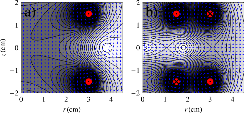
To date, all experimental cold atom storage rings are generated with magnetic fields where the (fixed) radius of the ring is determined by the radii of the ring’s magnetic elements (Fig. 1). Additionally, these storage rings are formed at a zero in the magnetic field, thus atoms - particularly the cold atoms - can spin-flip into non-trapped magnetic quantum states at the centre of the ring [9]. A long current-carrying wire along the symmetry () axis of the storage ring can generate an azimuthal magnetic field around the ring, preventing spin-flip losses [10]. However, optical access to the storage ring is limited by such a wire, and the wire must either be in-vacuo or a ‘hole’ in the vacuum chamber is required. We present a new variable-radius magnetic storage ring. In addition we show how, by adding a time-orbiting term to the magnetic field, it is possible to create a storage ring which is stable with respect to spin flips, without the necessity of an axial current-carrying wire.
We note that a cold molecule storage ring based on electric dipole forces has also been developed [11], however, although cold molecules are interesting in their own right, atoms are more suitable candidates for many interferometry experiments. In contrast to molecules, atoms can easily be prepared in the same quantum state, and they can be cooled to temperatures hundreds of times colder than molecules due to the ease with which they can be laser cooled.
Magnetic atom-optical elements use the Stern-Gerlach potential an atom experiences whilst moving adiabatically in a magnetic field of magnitude where is the Bohr magneton, is the atom’s hyperfine magnetic quantum number, and is the Landé g-factor. We consider weak-field-seeking atoms
We begin by discussing a second-order model for the magnetic field, as it neatly describes the main features of the storage ring. However, this approximation is only used as an illustration and all figures in this paper are calculated using the full Biot-Savart law for circular coils [14]. If a cylindrically symmetric magnetic coil configuration is used, then Maxwell’s equations and the on-axis behaviour of the magnetic field lead to the complete 3D Taylor expansion of the magnetic field. In particular, the second-order on-axis 1D magnetic field, gives the complete 3D second-order magnetic field:
| (1) |
We note that these results are contrary to those of Ref. [12], where the behaviour of the axial magnetic field in the radial plane was used to generate a 3D second-order magnetic field different to that of Eq. 1.
An axially-separated double trap [13] is formed when and a ring trap is formed when By solving Eq. 1 and finding the magnetic field zero, the radial and axial location of the storage ring are found:
| (2) |
The gradient of the magnetic field magnitude near the centre of the storage ring is identical in the axial and radial directions,
| (3) |
and atoms experience a potential which is approximately conical:
| (4) |
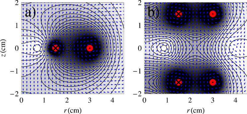
The simplest geometry for creating a ring trap is with two concentric co-planar circular coils of radius and respectively, carrying currents with magnitudes and in opposite directions (Fig. 2 a)). The radius of the storage ring is adjusted by varying the ratio of currents in the coils. Such a storage ring is formed in the plane of the two coils, and therefore requires an in-vacuo coil system. Two axially-displaced concentric coils can also be used to form the storage ring. However, the symmetry and additional confinement provided by two concentric, equally spaced, pairs of opposing ‘Helmholtz’ coils, make them a more apt configuration for an ex-vacuo coil system (Fig. 2 b)). Note that the orientation of the currents in the standard two and four coil storage ring (Fig. 1) is different from the equivalent variable radius storage ring (Fig. 2). The maximum coil current used in all of our figures is Amp-turns, which is identical to some of the coils used in our existing storage ring experiment [7, 10].
In order to generate a time-orbiting ring trap (TORT) we simply need to time-dependently alter the radial and axial position of the ring of zero magnetic field (given approximately in Eq. 2). In particular, adding small sinusoidally varying and terms mainly shift the and positions, respectively, of the storage ring magnetic zero point. Varying and in quadrature leads to the kind of magnetic field zero trajectory shown in Fig. 3 b). This effect can be either be achieved by using separate pairs of anti-Helmholtz and Helmholtz and or ‘true’ Helmholtz coils, or by adding sinusoidal modulations with the appropriate amplitude and relative phase to the two separate coils of one of the Helmholtz coil pairs in Fig. 2 b). For the magnetic zero trajectory shown in Fig. 3 b), we change the currents of the ‘pure’ Helmholtz coils at radius in Fig. 2 b) from to and where and change the and position of the storage ring, respectively.

A TORT trap transforms a storage ring’s conical magnetic potential (Eq. 4) into a time-averaged hyperbolic potential. A useful parameter is the time-averaged magnet field magnitude at trap centre The frequency of the TORT current modulation needs to be at approximately the geometric mean of the harmonic TORT trap frequency and the trap’s Larmor frequency [9]. This frequency is typical for time-orbiting quadrupole traps, and we note that the coils involved in both time-orbiting quadrupole and ring traps have similar dimensions. We have concentrated here on a time-orbiting variant of our adjustable-radius storage ring, however similar techniques exist for making a time-orbiting fixed-radius storage ring.
In order to make a Bose condensate in the storage ring, it is necessary to localise the atoms in a magnetic potential that is three-dimensionally harmonic for efficient evaporative cooling. In Ref. [10] we discuss how we use four magnetic pinch coils to transform a sector of a storage ring into both a magneto-optical trap [15] and a Ioffe-Pritchard magnetic trap [16]. The same technique can be used with our adjustable-radius storage ring. After evaporative cooling and subsequent condensation in the Ioffe-Pritchard trap, the pinch coils can be adiabatically turned off and Bragg scattering [17] can be used to coherently launch condensate wavepackets around the TORT.
An important limitation to the performance of interferometers using Bose-Einstein condensates is that in storage rings (and other traps with elongated geometries), condensates break up into fragments with different phases. Such phase fluctuations [18] can be reduced if the temperature in the trap is very low. The tunable radius of the ring allows one to find ideal conditions for Sagnac interferometry: i.e. by finding the maximum ring area over which phase fluctuations are negligible.
We believe that an adjustable-radius magnetic storage ring trap for Bose-condensed atoms
will be a very useful atom-optical tool. Additionally, our novel time-orbiting ring trap
(TORT), does not require an axial current-carrying wire, providing a high optical access
method for spin-flip loss prevention near a storage ring’s circular magnetic field zero.
Our scalable storage ring will allow one to study persistent currents, and probe the
fundamental limits of Bose-Einstein condensate Sagnac interferometry.
This research was supported by the UK EPSRC, the University of Strathclyde and INTAS.
References
References
- [1] Adams C S and Riis E 1997 Prog. Quant. Electr. 21 1
- [2] Chu S 1998 Rev. Mod. Phys. 70 685; Cohen-Tannoudji C N 1998 Rev. Mod. Phys. 70 707; Phillips W D 1998 Rev. Mod. Phys. 70 721
- [3] Cornell E A and Wieman C E 2002 Rev. Mod. Phys 74 875; Ketterle W 2002 Rev. Mod. Phys 74 1131
- [4] Hinds E A and Hughes I G 1999 J. Phys. D 32 R119
- [5] Goepfert A et al. 1999 Appl. Phys. B 69 217
- [6] Sauer J A, Barrett M D and Chapman M S 2001 Phys. Rev. Lett. 87 270401
- [7] Arnold A S, Garvie C S and Riis E 2002, http://www.photonics.phys.strath.ac.uk/Research/BEC/Ring.html;
- [8] Rooijakkers W et al. 2003, http://www.eps.org/aps/meet/DAMOP03/baps/abs/S390008.html
- [9] Petrich W et al. 1995 Phys. Rev. Lett. 74 3352
- [10] Arnold A S and Riis E 2002 J. Mod. Optics 49 95
- [11] Crompvoets F M H et al. 2001 Nature 411 174
- [12] Ketterle W and Pritchard D E 1992 Appl. Phys. B 54 403
- [13] Thomas N R, Wilson A C and Foot C J 2002 Phys. Rev. A 65 063406
- [14] Jackson J D 1999 Classical Electrodynamics 3rd edn (New York: Wiley) p 182; Good R H 2001 Eur. J. Phys. 22 119
- [15] Raab E L et al. 1987 Phys. Rev. Lett. 59 2631
- [16] Pritchard D E 1983 Phys. Rev. Lett. 51 1336
- [17] Stenger J et al. 1999 Phys. Rev. Lett. 82 4569; Kozuma M et al 1999 Phys. Rev. Lett. 82 871
- [18] Petrov D S, Shlyapnikov G V and Walraven J T M 2001 Phys. Rev. Lett. 87 050404; Dettmer S et al. 2001 Phys. Rev. Lett. 87 160406; Hellweg D et al. 2003 Phys. Rev. Lett. 91 010406; Richard S et al. 2003 Phys. Rev. Lett. 91 010405