Dynamics of semifluxons in Nb long Josephson 0- junctions
Abstract
We propose, implement and test experimentally long Josephson 0- junctions fabricated using conventional Nb-AlOx-Nb technology. We show that using a pair of current injectors, one can create an arbitrary discontinuity of the Josephson phase and in particular a -discontinuity, just like in -wave/-wave or in -wave/-wave junctions, and study fractional Josephson vortices which spontaneously appear. Moreover, using such junctions, we can investigate the dynamics of the fractional vortices — a domain which is not yet available for natural 0--junctions due to their inherently high damping. We observe half-integer zero-field steps which appear on the current-voltage characteristics due to hopping of semifluxons.
pacs:
74.50.+r, 85.25.Cp, 74.20.RpI Introduction
Theoretical and experimental investigation of Josephson junctions (JJs) made of unconventional superconductors showed that one can get so-called Josephson junctionsBulaevskiĭ et al. (1977), for which the first Josephson relation has the form , instead of . There can be different reasons for this. For example, in JJs formed using anisotropic superconductors with -wave order parameter symmetry the additional phase shift of happens when charge carries enter the negative lobe of the order parameter and exit from the positive lobe. Experimental realizations of -junctions include junctions formed at the boundary between two crystalline films of cuprate superconductors with different orientationsTsuei and Kirtley (2000), ramp junctions between -wave and -wave superconductorsSmilde et al. (2002); Hilgenkamp et al. (2003) or JJs with ferromagnetic barrier Kontos et al. (2002); Ryazanov et al. (2001).
If one considers a 1D long Josephson junction (LJJ) made of alternating 0 and parts, half-integer flux quanta (so-called semifluxonsGoldobin et al. (2002); Xu et al. (1995)) may spontaneously form at the joints between 0 and parts. Semifluxons were observed using SQUID microscopy in different types of 0--LJJsHilgenkamp et al. (2003); Kirtley et al. (1999, 1996).
Semifluxons are very interesting objects which have not been studied in detail, especially experimentally. They are very different from integer fluxons. Fluxons are solitons, but semifluxons are not — they are spontaneously formed and pinned at the 0--boundary. Consequently a semifluxon of either polarity represents the ground state of the system, while a fluxon moving in the LJJ always represents an excited state. This makes semifluxons attractive e.g. for information storage and processing in classical and quantum regimes. In spite of pinning, semifluxons are able to hop from one 0--boundary to the other provided that they are not very far from each other. A chain of semifluxons usually exists in the antiferromagnetic ground state but can be “polarized” by means of an applied dc bias currentGoldobin et al. (2003). A semifluxon has an eigen-mode oscillation frequency, so a 1D array of semifluxons has an energy band similar to the one in real crystals. By controlling the spacing between semifluxons (length of 0 and -pieces) one can control the properties of such an artificial 1D crystal.
In this letter we propose and implement LJJs based on conventional superconductors which allow one to study arbitrary fractional vortices111Arbitrary fractional vortices may also appear in a LJJ with a strong second harmonic in the current-phase relation, which can be present either intrinsically or due to a faceted grain-boundary (frequently alternating regions of size of negative and positive critical current). In contrast to such “splintered” vortices which were also observed experimentallyMints et al. (2002), the fractional vortices discussed here are pinned at a single 0--boundary. and, in particular, their dynamics. Up to now this is not possible using natural 0--junctions which typically have a Stewart-McCumber parameter or even smaller. Having much lower damping, we succeeded to observe half-integer zero-field steps in the current-voltage characteristics which appears due to a non-trivial effect — hopping of semifluxons between neighboring 0--boundaries. Low damping is also important in terms of future observations of macroscopic quantum effects involving fractional quantaKato and Imada (1997).
II The Model
The dynamics of the Josephson phase in LJJs consisting of alternating 0 and parts can be described by the 1D perturbed sine-Gordon equationGoldobin et al. (2002)
| (1) |
where is the Josephson phase and subscripts and denote the derivatives with respect to coordinate and time . In Eq. (1) the spatial coordinate is normalized to the Josephson penetration depth and the time is normalized to the inverse plasma frequency ; is the dimensionless damping; is the external bias current density normalized to the critical current density of the junction. The function is a step function which is -discontinuous at all points where 0 and parts join. According to Eq. (1), is also -discontinuous at the same points as . We call these points phase discontinuity points.
To describe 0--LJJs one can use directly the equation with alternating critical current densityXu et al. (1995); Smilde et al. (2002); Kirtley et al. (1997); Buzdin and Koshelev (2003)
| (2) |
written for the continuous phase . Equations (1) and (2) are equivalentGoldobin et al. (2002)222For a single semifluxon the difference between and is demonstrated in Fig. 2 of Ref. Goldobin et al., 2002.
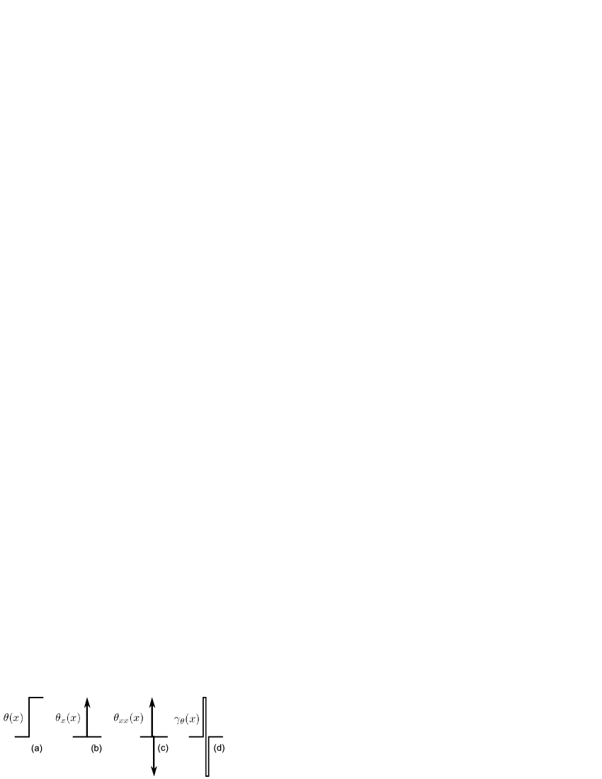
Is it possible to create a 0--LJJ (LJJ with -discontinuity) using a conventional LJJ? The fact that a junction is 0- is contained in the term. If is a set of steps, then is a set of singularities as shown in Fig. 1(a)–(c). If we do not have initially the term in Eq. (1), we can substitute its effect by introducing a properly shaped bias current in addition to the main bias current . To mimic one -discontinuity the profile should be the one shown in Fig. 1(c). For the sake of practical treatment, one can approximate it by two rectangular pulses, as shown in Fig. 1(d). Such a bias profile can be created by two current injectors of width situated as close as possible to each other. The current of the amplitude flowing from one injector to another should create a -discontinuity of the Josephson phase. Thus one can create an artificial 0--LJJ provided that the width of the whole injector construction is well below . Note that, passing different currents, one can create arbitrary -discontinuities instead of a -discontinuity, and study arbitrary fractional vortices, if they appearGoldobin et al. (2003). This concept is a generalization of the idea to use a pair of injectors to insert a fluxon (-discontinuity) in an annular LJJUstinov (2002).
In conventional LJJs the phase is continuous while . When we increase the phase develops a jump at . In practice, instead of a jump we have a rapid increase of the phase from to over a small but finite distance. Physically this means that by passing a rather large current through the piece of the top electrode between two injectors we “twist” the phase by over this small distance, i.e., we insert a magnetic flux equal to in a small distance between injectors. This flux has a characteristic size of the order of the distance between injectors or of their width. The junction may react on the appearance of such a discontinuity by forming a solution [or ] which changes on the characteristic length outside the injector area, and corresponds, e.g., to the formation of a fractional Josephson vortex, as discussed below.
In the experiment the injectors are never ideal due to technological constraints and one has to calibrate them to know the value of current needed to get, e.g., a -discontinuity. We do this by measuring the dependence of the critical current of the LJJ on the current through the injectors , and comparing the obtained dependence with the dependence calculated theoretically. As a result we get .

The curve ( is the maximum normalized supercurrent) numerically calculated for (like in our samples) is shown in Fig. 2. Details on the calculation of for different will be given elsewhereGoldobin et al. . It is important to note that has maxima at and cusp-like minima (possibly with hysteresis) at . The value of at the minimum depends on the junction length and varies from 0 for a short junction to for an infinitely long oneGoldobin et al. .
III Experiment
III.1 Implementation
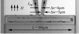
The samples were fabricated333Hypres, Elmsford (NY), USA. http://www.hypres.com using standard Nb-AlOx-Nb technology with low critical current density to have as large as possible in comparison with the injector size. Data reported here were obtained from the sample shown in Fig. 3 at .
The measured - characteristics (IVCs) and dependences (presented below) ensure good sample quality and the absence of trapped magnetic flux.
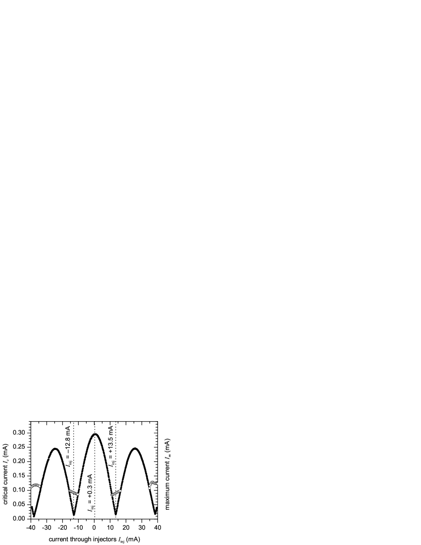
To calibrate the injectors, we measured the dependence at shown in Fig. 4. Obviously, the dependence is similar to Fig. 2, and the minimum is about of the maximum , in agreement with numerical calculations for . From Fig. 4 we find that corresponds to and corresponds to . The pattern is slightly shifted along the axis probably due to self-field effects. Thus, the maximum is reached at .
The value of at the maxima slowly decreases with increasing . This effect can be reproduced in numerical simulations using the model (1) for injectors with finite and like in our samples.
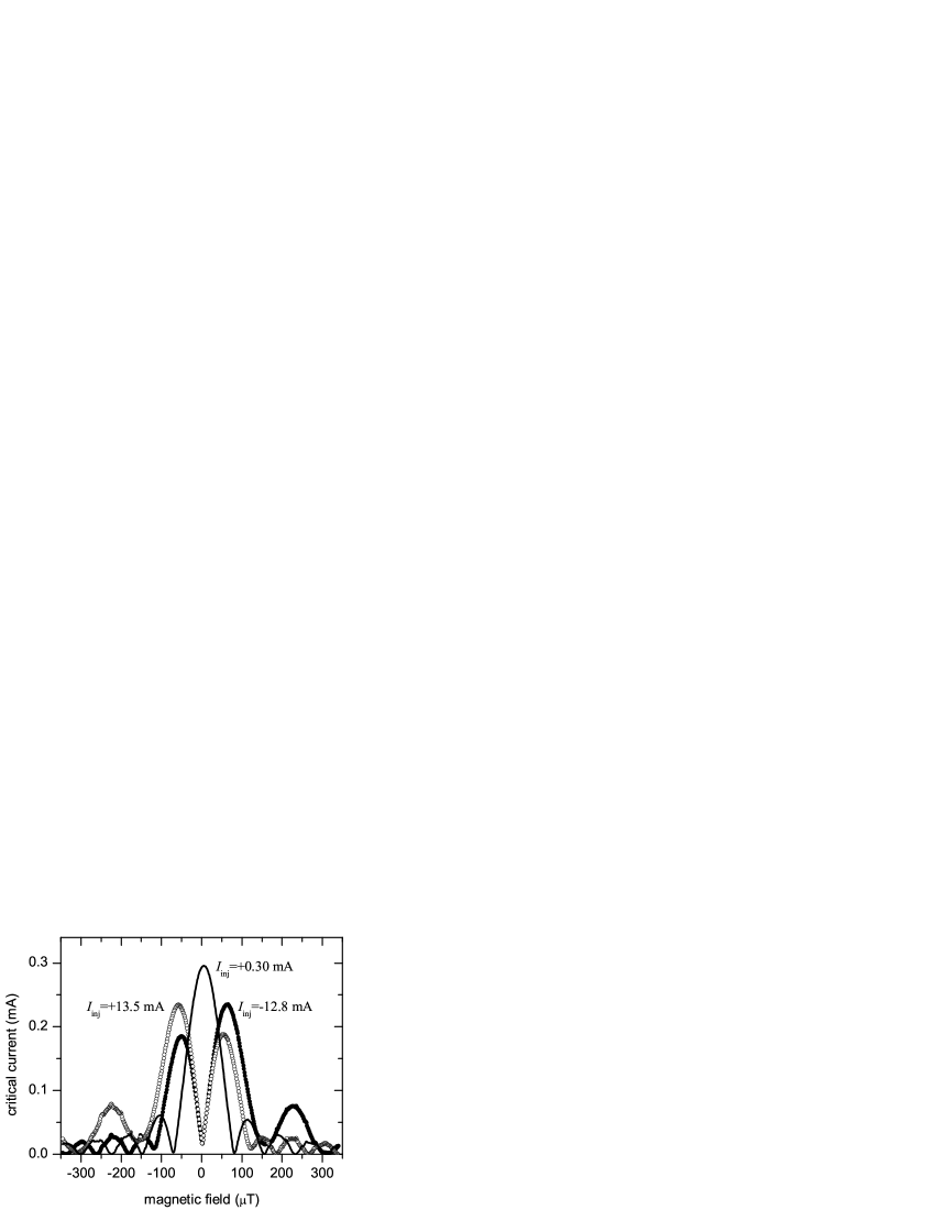
One of the specific features of natural 0--junctions is the minimum in the dependence at Smilde et al. (2002). It was calculatedKirtley et al. (1997) that when the 0--junction is short () the minimum is very deep and reaches zero at . As increases, the minimum gets more shallow and at almost disappears. In our artificial 0--LJJ with the minimum should be strongly developed. We have measured and compared at (no discontinuity) and at at ( and ). The results are presented in Fig. 5 and are in good agreement with the predictionKirtley et al. (1997). One can notice that at each value of corresponding to a 0--LJJ, the left and right lobes of the curve look somewhat asymmetric with the period of oscillations being different for and . Again, this is related to the finite distance and width of the injectors and can be reproduced in simulations. A similar asymmetry has been calculated in Ref. Harlingen, 1995 (Fig. 12, the last -wave plot) where the “inserted” flux is due to a trapped vortex, coupling to the center of a conventional junction. If the size of the trapped vortex (in our case and ) approaches zero, approaches a perfectly symmetric shape with equal oscillation periods at and (see Fig. 12 of Ref. Harlingen, 1995, the first -wave plot).
III.2 Semi-integer zero-field steps
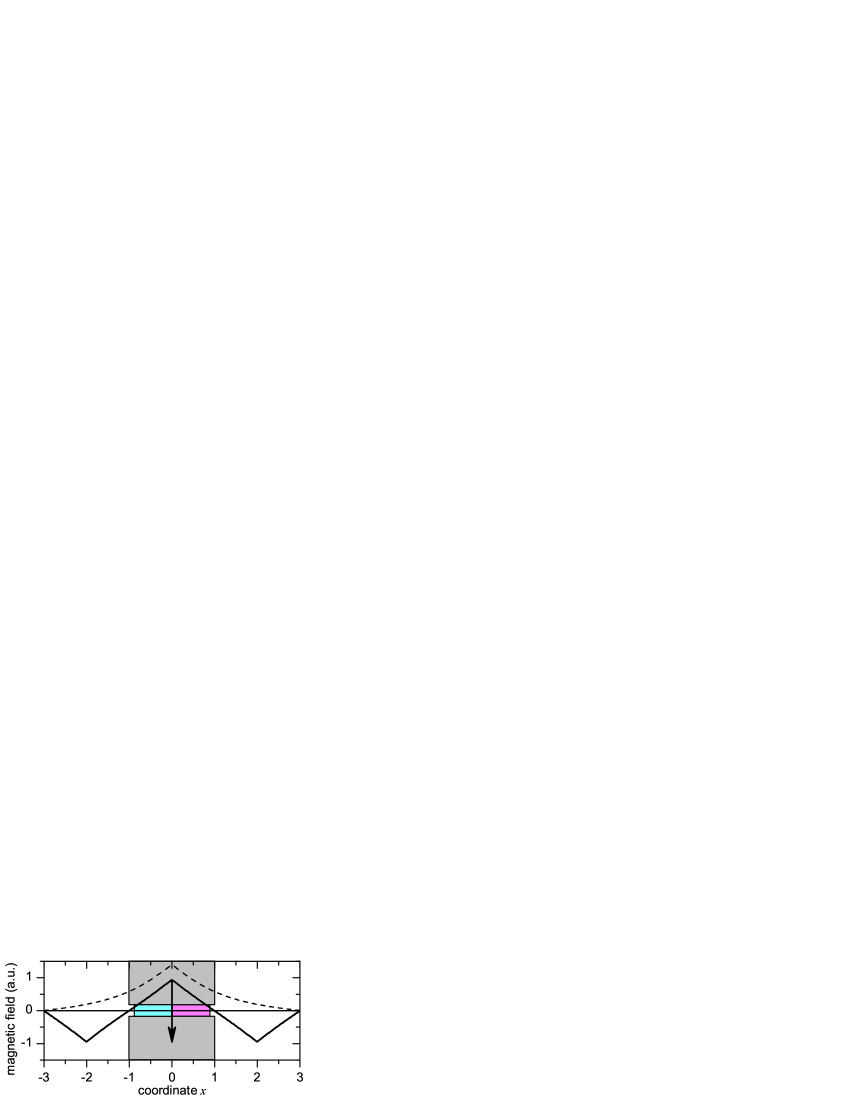
When a LJJ has a -discontinuity in its center, the ground state consists of a semifluxon spontaneously formed and pinned at the -discontinuityKirtley et al. (1997); Goldobin et al. (2002, 2003), as shown in Fig. 6. When the semifluxon solutionXu et al. (1995); Goldobin et al. (2002), shown in Fig. 6 by a dashed line, is not valid anymore as it does not satisfy the boundary conditions . The semifluxon solution derived in Refs. Xu et al., 1995; Goldobin et al., 2002 is valid in an infinite LJJ only. To construct the solution for a LJJ of finite length, we introduce images (anti-semifluxons) situated outside the left and the right edge of the junction at a distance of from each edge444To balance the problem completely, one needs to introduce an infinite chain of images: positive semifluxons at and negative semifluxons at .. The final magnetic field profile is shown in Fig. 6 by the thick solid line.
If one applies a bias current to a chain of antiferromagnetically ordered semifluxons, the semifluxons can rearrangeGoldobin et al. (2003): the positive semifluxon at hops to the -discontinuity at and the image hops from to . This process is accompanied by a transfer of flux equal to across the right edge of the junction. Subsequently the same mutual hopping happens at the left edge of the junction and the flux equal to is transferred across the left edge too. This is repeated periodically in time, and the net transferred flux results in a finite voltage across the junction. This process is very similar to the dynamics which takes place in a LJJ biased at the zero-field step (ZFS)555 Since our LJJ has intermediate length, we speak here about ZFS which are better described by a multi-mode approachEnpuku et al. (1981) rather than by perturbation theoryPedersen and Welner (1984); Levring et al. (1982, 1983) .
Presuming that the flux in our 0--LJJ is transferred with the same maximum velocity, but only rather per hopping/reflection, we should observe half-integer ZFS on the IVC of the 0--LJJ, as was recently predicted by StefanakisStefanakis (2002). Note that to observe semi-integer ZFS the 0--LJJ should be not very long () so that the semifluxons can still hop over this distance.
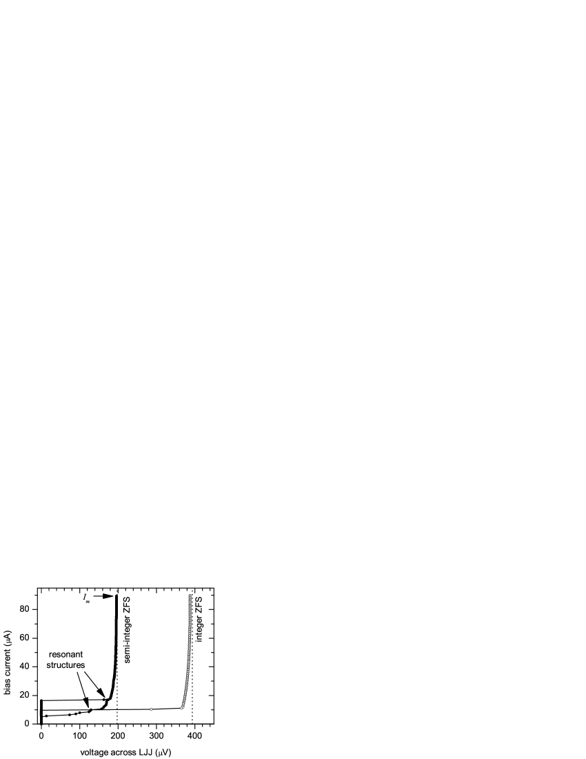
In Fig. 7 we show two IVCs taken at : one with a classical ZFS recorded at and another with a semi-integer ZFS registered at . The asymptotic voltage of the ZFS is , while for the semi-integer ZFS it is . Thus, with accuracy of . This is the experimental confirmation of the existence of semi-integer ZFSStefanakis (2002) and semifluxon hoppingGoldobin et al. (2003). We also observe resonant structures at the half-integer ZFS, which is similar to structures we see in simulations. This kind of resonances typically appear when magnetic flux moves in a LJJ with inhomogeneitiesUstinov (1996).
We also measured the behavior of the semi-integer ZFS as a function of and found that the asymptotic voltage of the semi-integer ZFS does not depend on . When , one has two types of fractional vortices in the system: a vortex at and two images (antivortices) at . When the vortex and antivortex hop and exchange positions, the total flux transferred is still (they exchange a virtual fluxonGoldobin et al. (2003)). Although the voltage of the semi-integer ZFS is not affected by , the amplitude of the step changes with until the step gets completely hidden by the critical current. The dependence of the maximum current of the semi-integer ZFS on is shown in Fig. 4. No high order ZFSs were observed since our LJJ is rather short ().
IV Conclusions
In conclusion, we have proposed, implemented and tested experimentally long Josephson junctions based on Nb-AlOx-Nb technology with an arbitrary -discontinuity of the Josephson phase created by passing a current through a pair of injectors. Formally this system is equivalent to a 0- long Josephson junction made of unconventional superconductors and allows one to study the dynamics of fractional vortices. We confirmed the hopping of semifluxons under the action of applied bias current which manifests itself as the appearance of semi-integer zero field steps in the current-voltage characteristics of the junctions.
Among the many interesting physical questions concerning the physics of fractional vortices we just mention two examples for which arbitrary quantization and/or low damping are essential: (1) How does the eigen-frequency of a fractional vortex depend on the flux carried by it? How does the coupling between neighboring fractional vortices affect their eigen-modes (eigen-mode splitting) and can one construct an artificial 1D crystal with controllable energy bands? (2) Does a semifluxon behave as a spin- particle? Can it make quantum transitions or be in a superposition of both states or does flux conservation prevent this? Can one create superpositions of states such as for two coupled semifluxons? Finally, we note that an annular system with e.g. three semifluxons may serve as an interesting system to study frustration effects.
Acknowledgements.
We acknowledge discussions with B. Chesca and support by the Deutsche Forschungsgemeinschaft, and by the ESF programs ”Vortex” and ”Pi-shift”.References
- Bulaevskiĭ et al. (1977) L. N. Bulaevskiĭ, V. V. Kuziĭ, and A. A. Sobyanin, JETP Lett. 25, 290 (1977), [Pis’ma Zh. Eksp. Teor. Fiz. 25, 314 (1977)].
- Tsuei and Kirtley (2000) C. C. Tsuei and J. R. Kirtley, Rev. Mod. Phys. 72, 969 (2000).
- Smilde et al. (2002) H. J. H. Smilde, Ariando, D. H. A. Blank, G. J. Gerritsma, H. Hilgenkamp, and H. Rogalla, Phys. Rev. Lett. 88, 057004 (2002).
- Hilgenkamp et al. (2003) H. Hilgenkamp, Ariando, H.-J. H. Smilde, D. H. A. Blank, G. Rijnders, H. Rogalla, J. R. Kirtley, and C. C. Tsuei, Nature 422, 50 (2003).
- Kontos et al. (2002) T. Kontos, M. Aprili, J. Lesueur, F. Genêt, B. Stephanidis, and R. Boursier, Phys. Rev. Lett. 89, 137007 (2002).
- Ryazanov et al. (2001) V. V. Ryazanov, V. A. Oboznov, A. Y. Rusanov, A. V. Veretennikov, A. A. Golubov, and J. Aarts, Phys. Rev. Lett. 86, 2427 (2001).
- Goldobin et al. (2002) E. Goldobin, D. Koelle, and R. Kleiner, Phys. Rev. B 66, 100508 (2002).
- Xu et al. (1995) J. H. Xu, J. H. Miller, and C. S. Ting, Phys. Rev. B 51, 11958 (1995).
- Kirtley et al. (1999) J. R. Kirtley, C. C. Tsuei, and K. A. Moler, Science 285, 1373 (1999).
- Kirtley et al. (1996) J. R. Kirtley, C. C. Tsuei, M. Rupp, L. S. Y.-J. J. Z. Sun, A. Gupta, M. B. Ketchen, K. A. Moler, and M. Bhushan, Phys. Rev. Lett. 76, 1336 (1996).
- Goldobin et al. (2003) E. Goldobin, D. Koelle, and R. Kleiner, Phys. Rev. B 67, 224515 (2003), cond-mat/0209214.
- Kato and Imada (1997) T. Kato and M. Imada, J. Phys. Soc. Jpn. 66, 1445 (1997), cond-mat/9701147.
- Kirtley et al. (1997) J. R. Kirtley, K. A. Moler, and D. J. Scalapino, Phys. Rev. B 56, 886 (1997).
- Buzdin and Koshelev (2003) A. Buzdin and A. E. Koshelev, Phys. Rev. B 67, 220504 (2003).
- Ustinov (2002) A. V. Ustinov, Appl. Phys. Lett. 80, 3153 (2002).
- (16) E. Goldobin et al., in preparation.
- Harlingen (1995) D. J. V. Harlingen, Rev. Mod. Phys. 67, 515 (1995).
- Stefanakis (2002) N. Stefanakis, Phys. Rev. B 66, 214524 (2002), see also nlin.ps/0205031.
- Ustinov (1996) A. V. Ustinov, JETP Lett. 64, 191 (1996), [Pis’ma Zh. Eksp. Teor. Fiz. 64, 178 (1996)].
- Mints et al. (2002) R. G. Mints, I. Papiashvili, J. R. Kirtley, H. Hilgenkamp, G. Hammerl, and J. Mannhart, Phys. Rev. Lett. 89, 067004 (2002).
- Enpuku et al. (1981) K. Enpuku, K. Yoshida, and F. Irie, J. Appl. Phys. 52, 344 (1981).
- Pedersen and Welner (1984) N. F. Pedersen and D. Welner, Phys. Rev. B 29, 2551 (1984).
- Levring et al. (1982) O. A. Levring, N. F. Pedersen, and M. R. Samuelsen, Appl. Phys. Lett. 40, 846 (1982).
- Levring et al. (1983) O. A. Levring, N. F. Pedersen, and M. R. Samuelsen, J. Appl. Phys. 54, 987 (1983).