Current-driven domain wall motion in thin ferromagnetic wires
S. E. Barnes and S. Maekawa
Institute for Materials Research, Tohoku University,
Sendai 980-8577, Japan
Abstract
The coupling between a current and a Bloch wall is examined in the half-metal limit of the double exchange model. The conduction electrons transfer angular momentum to the Bloch wall with 100% efficiency in the absence of pinning. The wall is displaced without distortion with velocity proportional to the current. In the presence of a pinning potential either the angular momentum is destroyed by the perpendicular component of the anisotropy field or is converted to coherent magnons.
A moving wall has its velocity reduced by pinning. The expression for the velocity agrees surprisingly well with experiment.
pacs:
75.60.-d, 73.40.Cg, 73.50.Bk, 75.70. i
††preprint: LL8931
Spintronic devices have great technological promise but represent a challenging problem at both an applied and fundamental level. It has been shown theoretically100 ; 5 that the direction of a magnetic domain might be switched using currents alone. Devices designed to use this principle often consist of multilayers of magnetic and non-magnetic materials. The advantages of similar devices based upon the current induced displacement of Bloch wall are simplicity and the fact that the switching current is smaller1 ; 2 ; 3 . Experimentally the current induced displacement of a Bloch wall has been clearly demonstrated and in a recent experiment the velocity of the displaced wall was measured3 .
In this Letter is developed a first principles theory for the coupling between a current and a Bloch wall based upon a standard model for ferromagnets, i.e., within the double exchange model. Great care is taken in order to ensure that angular momentum is conserved. Using the -exchange model, Berger5 shows the polarization of the -electrons rotates as it passes through a wall. The reaction force might then be assumed to cause wall movement. However, as will be shown, the situation is complicated. Angular momentum given to the wall can be taken up either by (i) the displacement of the wall, (ii) the production of coherent spin waves or (iii) a rotation of the wall so that the angular momentum is absorbed by the anisotropy energy. These issues are most easily addressed in the half-metal limit. This is technologically pertinent since it corresponds to the most efficient devices. Most work has been performed on Permalloy (Ni81Fe19). For this material, the current has a polarization 3 and so the present description based upon is not hopelessly unrealistic. When making comparison with experiment, the difference will be accounted for by adding factors of as appropriate.
The standard double exchange model is
(1)
where is the localized spin operator and
creates an electron with spin at site . The wire is assumed to extend along the -direction. That this an easy axis implies .
Corresponding to highly correlated electrons, the limit is taken. This permits a spinless majority electron operator to be defined, and in terms of this the minority
where is the conduction electron spin operator. A large Hund’s rule coupling is also assumed. With this only the largest total angular momentum manifold is relevant. At a site occupied by a conduction electron only states with need to be accounted for and it follows that . This is not an assumption about local equilibrium of the conduction electron but rather is an immediate and rigorous consequence of the Wigner-Eckart theorem.
The Holstein-Primakoff transformation6 , is used to quantize the spin degrees of freedom. In principle, the axes of quantization are arbitrary, however, as the standard theory of ferromagnetic magnons illustrates, in fact the local axis of quantization must be taken along the classical equilibrium direction, i.e., the spin direction in the limit . When this is the case the approach generates and expansion in . This local equilibrium direction is specified by the Euler angles and . In this Letter the solution will most often be time dependent. Rather than setting up the complicated equations of motion, here extensive use will be made of rotating frames. The aim is to reduce the problem to that of static equilibrium but within the time dependent frame. The time dependent solution is then obtained upon reverting to the laboratory frame.
In the absence of a wall, for large , the kinetic energy term is The Bloch wall is generated through via the static rotations by , and . For this large regime, the usual SU(2) rotation of the conduction electron operators simplifies to and the rotated Charge motion arises principally via where . The reduction of in the Bloch wall implies a barrier, however this has a height which is taken to be negligible compared to . The solutions of are, to a good approximation, plain -states independent of the wall position or its motion.
Using the Wigner-Eckart theorem, the part of linear in reduces to:
(2)
which is the key spin-charge current interaction. The, bi-linear in , part of is also of importance. When acting on eigenstates of these lead to a renormalization, , of the total exchange coupling . The effective concentration , assuming isotopic hopping.
A small wall translation by amounts to a small rotation generated by which defines .
That the translation leaves the energy unchanged implies that
creates a zero energy excitation localized in the wall. This special -mode is key to a understanding of not only the dynamics but also pinned static solutions of a Bloch wall. It is of the nature of a discrete Goldstone boson associated with the translational invariance of the wall.
The effective, , where is the classical energy functional, is given above and is the magnon Hamiltonian. The Bloch wall structure can be determined by minimizing . The standard result is with for . The wall width . The local axes change from to with increasing and the wall lies in the -plane.
The conservation of the spin angular momentum is a central issue. If the coupling to the contacts is ignored and , it follows that . A wall with speed implies and, in fact this must be equal to the surface integral where is the spin current. The conduction electrons have their spin reversed in the wall implying a contribution , the charge current. Such a finite surface term gives rise to a local term , the charge current density, in the equation for and will lead to wall motion even when .
Whatever the value of , the translational invariance of the Hamiltonian implies that the wall will move with a constant velocity in the presence of a charge current. In order to prove this, use is made of a rotating frame. Consider again the current carrying states which are eigenstates of . The spin-charge coupling reduces to
(3)
Here defined to be strictly perpendicular to the instantaneous axis of quantization. The only derivative which is finite during this short period is the similar instantaneous . This derivative can also be made to be zero by a suitable rotating frame, i.e., via so that and . The wall is therefore stationary, when the local axes of quantization rotate according to
(4)
The solution of this is where is the static solution. In the laboratory frame, the wall is translated without distortion. The velocity 3 ; 7 is such that the net conduction electron spin current which enters the wall is exactly compensated by the similar current implied by its uniform displacement.
The simplest model for the pinning of the Bloch wall is to reduce by a small amount the anisotropy energy at the origin. The added term generates a pinning gap . The problem of such a pinned wall is surprisingly complicated. Our results developed below show, for finite , the wall tilts by an angle and the critical charge current is determined by the condition that . However, when is negligible, the wall generates magnons which take away the conduction electron angular momentum given to the wall. In this case, is found to reflect the equality of the rate of creation of linear magnon momentum to the maximum force generated by the pinning.
The largest pinning gap arises when the wall is centered at the origin, i.e., with . Explicitly then, and the diagonal part of . The value of is determined by evaluating the commutator , which is equivalent to taking the expectation value with respect to the -magnon wave function, and, with , gives,
(5)
The wall can now tilt so that is finite. The anisotropy contains which gives the -mode an energy shift of . The maximum allowed value of therefore corresponds to . This is related to the current through the terms in which are linear in and . These are imaginary and can be written as . This cancels if
whence eliminating , assuming this is small, gives a critical current
(6)
If is small there is an intrinsic maximum current,
for , which will be reached before . It follows for
large that and is negligible. In order to conserve angular momentum, the wall must now produce magnons, i.e., be time dependent. Sought again are current carrying eigenstates. To the wall is added a twist characterized by and the solution is rendered stationary by a rotation of angular frequency about the new axes and . The final axes of quantization then correspond to and . The effect of such a rotation is to add an effective magnetic field which has an component perpendicular to the , axis. The twist of the bond by is introduced by . Equilibrium, in the rotating frame, implies zero coefficients of bothand . The easiest fashion by which to establish these equilibrium conditions is to observe the local while . Given that, e.g., rotates the th spin by a small it is easy to show by evaluating that the coefficient of in must be where is the already defined classical energy. The exchange part of this is . A small rotation by is generated rather by where . However contains no -numbers and so this rotation determines the coefficient of , i.e., this is . That the coefficient of be zero implies
. This can be re-integrated by to give back the energy to within a constant, i.e., it is implied that:
(7)
Using for the coefficient of is obtained
Integrating this with respect to results in an equation relating currents:
(8)
and gives
(9)
which, with Eqn. (7), gives an equation for . However, except to the extreme right of the wall, and Eqn. (7) gives directly while Eqn. (9) determines the twist . For the extreme right Eqn. (9) reduces to which equates spin currents and ultimately determines amplitude of the magnons leaving the system to the right, while Eqn. (7) reduces to which, correctly, equates the frequency of the rotating frame to the magnon energy. The whole solution is then parameterized by the value of . This, in turn, is determined by requiring that the absolute value of the ground state energy be a minimum. Given that the system is large compared to the width of the wall, the energy to be minimized it that of the coherent magnons to the right of the wall. The result is which corresponds a magnon energy per unit site of .
A relationship between and the force on the wall is obtained by considering a wall displacement generated by . For the displaced wall , not accounting for pinning. It follows that
and that there is force . Using shows contains . A similar term arises from the linear part of the pinning term, i.e., . Corresponding to , the maximum pinning force, is . Finally, the magnon de-pinning current is obtained:
(10)
This key result is equivalent to equating the rate of creation of linear magnon momentum to the maximum force produced by the pinning potential.
The voltage across the wall is easily deduced. For large , a non-polarized contact will inject majority electrons on the left and this defines as the chemical potential of the left contact. For an eigenstate, the energy to add the last electron cannot depend on position and thus is the chemical potential for these electrons. One could imagine measuring on the right with a spin polarized contact. The destruction of such an electron involves destroying a magnon and hence must be exactly higher in energy than , i.e., the majority and contact chemical potential to the right, i.e, for small currents. There is evidently a branch imbalance.
By design, Permalloy has a small intrinsic anisotropy and both and might be expected typically T. This is several orders of magnitude smaller than and it must be expected that, e.g., variations in the wire width lead to variations and pinning. The largest effect occurs for the components of with a length scale which are comparable to the wall width. In this case the pinning gap can be as large as . With this it would be the case that and the time dependent solution with will apply.
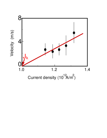
Figure 1: The experimental points are taken from [3]. The solid line is estimated to correspond to the value of from Eqn. (11) and to a A/m2. (This has been corrected for the fact that the experimental material has a polarization .)
Evidently to within the errors the conduction electron angular momentum, not destroyed by the pinning center is, transmitted to wall motion with efficiency equal to .
Having considered free motion and pinning it is easy to solve the problem of slow motion with a pinning potential. If a wall is moving slowly and there are many pinning centers, the wall will adiabatically adjust to remain in the ground state. The wall width is and therefore the characteristic time the wall, with velocity , interacts with the pinning center is and corresponds to an energy . Adiabacity requires that this be less that the energy of the magnons which are involved in the pinning deformations. At the worst these have a and the energy involved is the gap in spin wave spectrum. Adiabatically then implies which is times the maximum spin wave velocity. Given the experimental values3 correspond to m/s this criterion is surely satisfied.
The principle of the calculation is to
divide into two parts the rotating frames used to render the Bloch wall stationary, one of which corresponds to the translational motion and a second which reflects the pinning. The displacement corresponds to the rotation operator where . Given the adiabatic approximation is well satisfied the rotations can be absorbed into slowly time dependent conduction electron operators . In this moving frame, the effective current density is reduced to . Then following the calculation for pinning, the remaining rotations are those required for the pinned ground state. The resulting is given by Eqn. (10) and is determined by the pinning strength. The difference between the actual current and that which can be pinned is , and this in turn, determines and its relationship with the current . The velocity is given by:
(11)
where, as stated, is the given by Eqn. (10) except that average rather than maximum pinning strength is involved. The important result here is that is independent of , i.e., that part of the angular momentum current which is in excess of that converted to magnons by the pinning potential is 100% converted into motion of the wall. In Fig. (1) this prediction, corrected for , is compared with the experiments of Yamaguchi et al. Experimentally it is observed that there is a minimum velocity of m/s for which uniform motion is observed. It is reported that no motion of the wall is seen for currents smaller that A/m2 and taking this to be implies the solid line shown in the figure with a gradient which would correspond to .
What is strange is that the same velocity is reported for a currents in the range A/m2 to A/m2. It is unfortunate that it is not possible to follow the system to higher velocities in order to see if the initial points have to do with threshold effects, e.g., reflecting the first order nature of the transition to the magnon producing pinned state. The wall will be displaced during the time that the magnon amplitude is developed and, in a pulse experiment, this might be interpreted as depinning.
This work was supported by a Grant-in-Ad for Scientific Research on
Priority Areas from the Ministry of Education, Science, Culture and
Technology of Japan, CREST and NAREGI. The SEB is on a temporary leave from the
Physics Department, University of Miami, FL, U.S.A. and wishes to
thank the members of IMR for their kind hospitality.
References
(1) J. C. Sloncewski, J. Mag. Mag. Matr. 159, L1 (1996).
(2) L. Berger. Phys. Rev. B54, 9353 (1996).
(3) J. J. Versluijs, M. A. Bari, and J. M. D. Coey Phys. Rev. Lett. 87, 026601 (2001).
(4) D. A. Allwood, et al. Science 296, 2003-2006 (2002).
(5) A. Yamaguchi et al., Phys. Rev. Lett. 92, 077205 (2004).
(6) See e.g., C. Kittel, Quantum theory of solids, Wiley, New York (1963)
(7) G. Tatara, and H. Kohno, Phys. Rev. Lett. 92, 086601 (2004).