Spin and orbital structure of uranium compounds
on the basis of a - coupling scheme
Abstract
Key role of orbital degree of freedom to understand the magnetic structure of uranium compounds is discussed from a microscopic viewpoint by focusing on typical examples such as UMGa5 (M=Ni and Pt) and the mother compound UGa3. By analyzing an orbital degenerate Hubbard model constructed from the - coupling scheme in the cubic system, we obtain the phase diagram including several kinds of magnetic states. Especially, in the parameter region corresponding to actual uranium compounds, the phase diagram suggests successive transitions among paramagnetic, magnetic metallic, and insulating Néel states, consistent with the experimental results for AuCu3-type uranium compounds. Furthermore, taking account of tetragonal effects such as level splitting and reduction of hopping amplitude along the -axis, an orbital-based scenario is proposed to understand the change in the magnetic structure from G- to A-type antiferromagnetic phases, experimentally observed in UNiGa5 and UPtGa5.
pacs:
71.27.+a, 75.30.Kz, 75.50.Ee, 71.10.-wI Introduction
Recently, -electron compounds with the HoCoGa5-type “115” tetragonal crystal structure have been intensively investigated in both the experimental and theoretical research fields of condensed matter physics. Among such compounds, interesting magnetic properties have been reported for UMGa5, where M is a transition metal ion. U115-1 ; U115-2 ; U115-3 ; U115-4 ; Tokiwa ; U115-5 ; U115-6 ; U115-7 ; U115-8 In particular, neutron scattering experiments have revealed that UNiGa5 exhibits the G-type antiferromagnetic (AF) phase, while UPdGa5 and UPtGa5 have the A-type AF state. Tokiwa ; U115-8 Note that G-type indicates a three-dimensional Néel state, while A-type denotes a layered AF structure in which spins align ferromagnetically (FM) in the plane and AF along the axis.Wollan It is quite interesting that the magnetic structure is different for U-115 compounds which differ only by the substitution of transition metal ions.
U-115 materials have also been found to differ in their magnetic anisotropy. For M=Ni, Pd, and Pt, both and exhibit Curie-Weiss behavior, but is somewhat larger than ,U115-8 where and are magnetic susceptibilities for magnetic field parallel to the and axes, respectively. This anisotropy increases in the sequence UNiGa5, UPdGa5, and UPtGa5. On the other hand, for M=Co, Rh, Ir, Fe, Ru, and Os, both and are almost independent of temperature, since these are Pauli paramagnets, but in these cases is somewhat larger than . Nonetheless, we again observe a tendency for the anisotropy to become larger for the progression from to and then to M ions. Thus, it is characteristic of U-115 compounds that the magnetic properties are sensitive to the choice of transition metal ions.
Furthermore, UGa3, which is the mother compound of UMGa5, has also provided intriguing experimental results. It has been reported that UGa3 exhibits a G-type AF metallic phase in the low-temperature region,UGa3 but a “hidden” ordering different from the magnetic one has been suggested by resonant X-ray scattering measurements.Mannix Unfortunately, orbital ordering in UGa3 is not yet confirmed experimentally, but it may be an interesting possibility to understand the result of resonant X-ray scattering experiment on UGa3 based on the orbital-ordering scenario.
Here we note that one must pay close attention to the meanings of “spin” and “orbital” in -electron systems. Since they are tightly coupled with each other through a strong spin-orbit interaction, distinguishing them is not straightforward in comparison with -electron systems. This point can create serious problems when we attempt to understand microscopic aspects of magnetism and superconductivity in -electron compounds. Thus, it is necessary to carefully define the terms “orbital” and “spin” for electrons in a microscopic discussion of magnetism and superconductivity in uranium compounds. In order to overcome this difficulty, we have proposed to employ a - coupling scheme to discuss -electron systems.Hotta
Let us note the advantages of the - coupling scheme at the outset. First, it is quite convenient for the inclusion of many-body effects using standard quantum-field theoretical techniques, since individual -electron states are clearly defined. In contrast, in the coupling scheme we cannot use such standard techniques, since Wick’s theorem does not hold. Second we can, in principle, include the effects of valence fluctuations. In some uranium compounds, the valence of the uranium ion is neither definitely U3+ nor U4+, indicating that the -electron number takes a value between 2 and 3. In the - coupling scheme this is simply regarded as the average number of electron per uranium ion.
In this paper, then, we propose a new scenario based on the - coupling scheme in order to understand the magnetic properties of uranium compounds, of which UGa3 and UMGa5 are considered to be typical examples. A microscopic model constructed from the - coupling scheme is analyzed using an unbiased method, such as the Lanczos technique. For UGa3 we obtain a phase diagram, including the paramagnetic (PM) state and several types of AF phases. In particular, we note that the PM state is adjacent to an AF metallic phase, consistent with the experimental results for uranium compounds having the AuCu3-type crystal structure. We also discuss the orbital structure of the AF metallic phase. By taking account of the effects of two-dimensionality, we find that the change in magnetic structure from G- to A-type AF phases is reproduced, consistent with experimental results for UMGa5. Moreover, it is shown that the observed trends of the magnetic anisotropy within the UMGa5 series can be understood from the present results.
The organization of this paper is as follows. In Sec. II, we will introduce a microscopic model Hamiltonian formulated on the basis of the - coupling scheme. In Sec. III, numerical results for UGa3 and UMGa5 are discussed in detail and compared with experimental results. In Sec. IV, future developments are discussed and the paper is summarized. In the Appendix, we analyze the local -electron configuration in order to examine the validity of the - coupling picture -- experimental results on the level scheme in certain -electron materials. Throughout the paper, we use units such that ==1.
II Model Hamiltonian
In this section we derive a microscopic Hamiltonian for UGa3 and UMGa5 based on the - coupling scheme. Although it is difficult to determine the valence of the uranium ion, here we assume that the formal valence is U3+, including three electrons per ion. By considering the crystalline electric field (CEF) potential and Coulomb interactions, we then assign three electrons to states in the =5/2 sextet.
II.1 Local -electron states
First, we define the one -electron states in the AuCu3-type cubic crystal structure. The effects of tetragonality will be discussed later. From the work of Hutchings for the case of cubic symmetry, Hutchings we identify two eigen energies as for the doublet and for the quartet, where is a cubic CEF parameter.
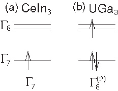
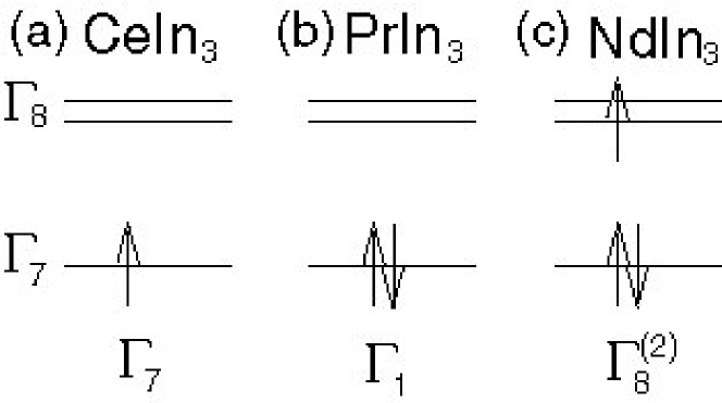
In order to proceed with the discussion, it is necessary to know which is lower, or , in the one -electron picture. For some crystal structures it is possible to determine the level scheme from intuitive discussions of -electron wavefunctions and the positions of ligand ions. However, this is not the case for the AuCu3-type crystal structure. For this case we invoke certain experimental results on CeIn3, a typical AuCu3-type Ce-based compound, where and have been reported as ground and excited states, respectively, with an energy difference of 12meV.Knafo Thus, we take to be lower for the present considerations, as shown in Fig. 1(a).
In the - coupling scheme for UGa3, we accommodate three electrons in the one-electron energy states and . There are two possibilities, i.e., low- and high-spin states, depending on the Hund’s rule interaction and the splitting between the and levels. Noting that the effective Hund’s rule interaction is small in the - coupling scheme,Hotta the low-spin state should be realized, as shown in Fig. 1(b). In fact, this low-spin state is also consistent with the coupling scheme. Details regarding electron configurations in the - coupling scheme are discussed in the Appendix.
In the electron configuration shown in Fig. 1(b), the level is fully occupied to form a singlet. If this level is located well below the , the occupying electrons will not contribute to the magnetic properties. Thus, we may be allowed to ignore the electrons for our present purposes, but this simplification will be examined more carefully in the following subsection.
II.2 Suppression of
First, we discuss the -electron kinetic term given by
| (1) |
where is the annihilation operator for an -electron with pseudospin in the -orbital at site , and is the -electron hopping matrix element between -and -orbitals along the direction. Indices and denote the and orbitals, respectively, while indicates the . Here, the pseudospin has been introduced to distinguish the two states of the Kramers doublet.
When we evaluate for nearest-neighbor hopping via the bond, it is given by
| (2) |
for the -direction,
| (3) |
for the -direction, and
| (4) |
for the -direction. Note that = in the cubic system. In this paper, is taken as the unit of energy. Later, will be treated as an extra parameter in order to take account of the tetragonality. We immediately notice that non-zero hoppings occur only among orbitals. Since the orbital has nodes along the cubic axes, it is localized in the present tight-binding approximation. This further justifies the suppression of .
One may question the foregoing approach on the grounds that it is based entirely on nearest-neighbor hopping processes. In order to address this concern, it is useful to examine the results of band-structure calculations, e.g., for CeIn3 (Ref. Betsuyaku, ) and UGa3 (Ref. Harima, ). Note that both results have been obtained assuming the system is in the paramagnetic state. In order to focus on the electron components of the energy band, we concentrate on the bands around the point near the Fermi level. For CeIn3, the energy band dominated by character is found to be lower than the -dominated band, consistent with the local level scheme in Fig. 1(a). An important point is that the Fermi level intersects the -dominant band, indicating that the Fermi surface is mainly composed of electrons hybridized with Ga-ion electrons.
On the other hand, for UGa3, the band is also lower than the band, but here the Fermi level crosses the band. Thus, the band appears to be fully occupied, consistent with the - coupling level scheme, as shown in Fig. 1(b). Since the main contribution to the Fermi surface comes from electrons, it is natural to dwell on the bands and ignore the occupied bands in giving further consideration to many-body effects.
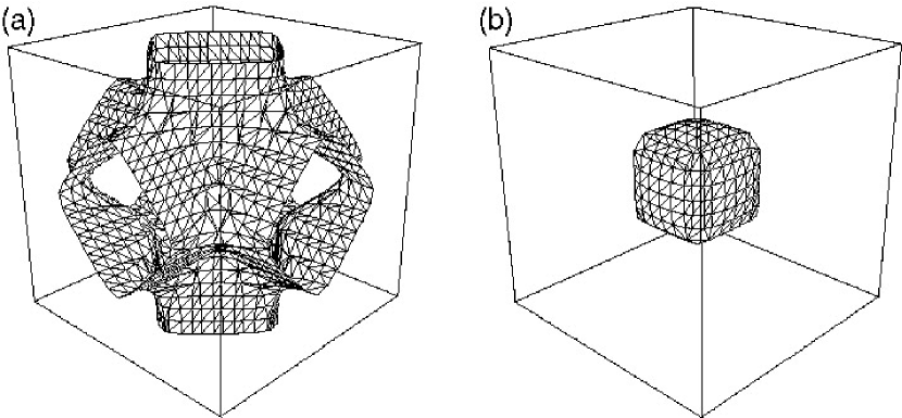
It is useful to consider the Fermi-surface structure of in comparison with that of the band calculations. In Fig. 2, we show Fermi-surface sheets derived from for the case of =1, where indicates the average number of electrons per site. Owing to the multi-orbital nature of the problem, we observe two Fermi-surface sheets. A cube-like Fermi surface is centered on the point and a second sheet is composed of three connected tubes along the three cubic axes.
In the band-structure calculation results, two Fermi surface sheets are also observed.Harima One sheet surrounds the point with a small hole at the center. Another is a large sphere-like Fermi surface centered at the R point. Since the carrier number is simply fixed at unity per site in the tight-binding model, it is difficult to obtain perfect agreement. Except for details, however, can reproduce the Fermi-surface structure of the band calculation in spite of its simplification.
II.3 model
Following the above discussion, the effective Hamiltonian for uranium compounds will be expressed by a -orbital degenerate Hubbard model, given as
| (5) |
where denotes the part of Eq. (1) and is written as
| (6) |
Here = and = . The level splitting between orbitals is introduced in order to consider certain tetragonal CEF effects for the case of UMGa5. When we analyze the magnetic properties of UGa3, this term is not needed. For the time being, is then set to be zero.
The Coulomb interaction term is given by
| (7) | |||||
where , , , and denote intra-orbital, inter-orbital, exchange, and pair-hopping interactions, respectively. These are expressed in terms of Racah parameters, and the relation =++ holds due to the rotational invariance in orbital space.Hotta For -electron systems, one also has the relation =. When the electronic wavefunction is real, this relation is easily demonstrated from the definition of the Coulomb integral. However, in the - coupling scheme the wavefunction is complex, and is not equal to in general. For simplicity, we shall assume here that =, noting that essential results are not affected. Since double occupancy of the same orbital is suppressed owing to the large value of , pair-hopping processes are irrelevant in the present case.
III Results
Among several possible methods to analyze the present microscopic model, in this paper we have employed the exact diagonalization technique. Although this has the drawback that it is difficult to enlarge the system size, this method offers the clear advantage that it is possible to deduce the magnetic structure in an unbiased manner. In order to discuss the ground-state properties, it is useful to calculate both the spin and orbital correlations, which are defined, respectively, by
| (8) |
with = and
| (9) |
with =. Here is the number of sites.
III.1 Cubic system
First let us consider the cubic system. Due to severe limitations of computer memory, our calculations are restricted to a 222 cube. Nonetheless, essential points on the spin structure can be captured. In Fig. 3(a), as a typical result for spin correlation, we show as a function of for =6. From the changes in the dominant component, we can define three regions as (I) 0.45, (II) 0.452.05, and (III) 2.05. In region I, the dominant component of appears at =, indicating a G-type AF structure. Definitions of spin structure are shown in Fig. 3(b). Note that for C-type [=, , ] and A-type [=, , ] structure, has the same value for each due to the cubic symmetry. In region II, 0.452.05, the cubic symmetry seems to be broken. Of course, this is spurious because of the smallness of the system, but for reasons given below, this phase is considered to be “metallic”, and it is conventionally called the PM phase. Note that the AF correlation with is still dominant for 0.450.8, indicating that the system is in a metallic magnetic phase. For 0.82.05, A-type AF correlations turn out to be dominant.
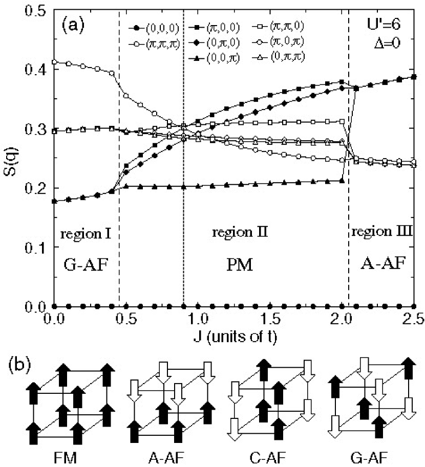
Here we discuss the evidence for a crossover between insulating and metallic behavior given by the spin correlation function. In an insulating phase, the spin structure is essentially determined by a round trip for an electron just between neighboring sites, leading to orbital-dependent superexchange interactions. Thus, cubic symmetry is maintained in the spin correlation function even for a small-sized cluster such as a 222 cube. However, in the PM metallic phase, electrons tend to gain kinetic energy by moving around the whole system. Such a motion depends sensitively on the anisotropy of the shape of the orbital. Specifically, in a small-sized cluster, the spin correlation function in the PM phase depends on the choice of the basis set for orbitals, and the cubic symmetry of the spin correlations appear to be broken owing to the smallness of the system. Thus, the spurious violation of cubic symmetry in the spin correlations is considered to be a signal for a metallic phase. Note that the metal-insulator boundary itself depends on the system size. In the thermodynamic limit, cubic symmetry should exist in the metallic phase, since the effect of orbital anisotropy is smeared by averaging over the whole system. In fact, the band dispersion relation has cubic symmetry, as is easily checked by diagonalizing in momentum space.
When we further increase the value of , the spin correlations recover cubic symmetry in region III, 2.05. Again we find an insulating phase, but the spin structure is now considered to be A-type AF. The change from G- to A-type AF phase with increasing can be understood in terms of the competition between kinetic and magnetic energies, in analogy with manganites.Hotta2 Namely, for large there is an energy gain for an FM spin pair on neighboring sites, but not for an AF spin pair. Thus, there is a tendency for the occurrence of ferromagnetism in the large- region. When we compare the magnetic energy of nearest-neighbor pairs, we notice that the number of FM pairs in the A-type AF phase is larger than for the G-type phase. Thus, for large values of the A-type phase appears.
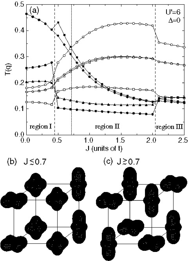
In Fig. 4(a) we show typical results for orbital correlations as a function of for =6. Corresponding to the changes in the dominant component of the spin correlation, we again see three regions. In region I (0.45), has two degenerate dominant components of = and . The orbital pattern is given by a mixture of two A-type orbital correlations, as schematically shown in Fig. 4(b). Since the Hamiltonian is not invariant under orbital exchange, should not have the same magnitude for =, , and . On the other hand, in region III (2.05) the component is dominant, suggesting a G-type orbital pattern as shown in Fig. 4(c).
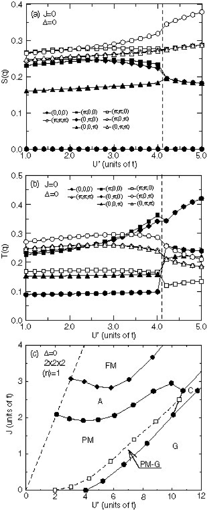
Now we focus our attention to the region II, in which we can see the crossover in the orbital pattern between Figs. 4(b) and (c). Note that the crossover point is different from that between G- and A-type AF phases observed in . This may be related to the appearance of two distinct transition temperatures of UGa3 around at .Mannix Namely, one is related to ordering of spin and another is originating from orbital degree of freedom. An interesting point is that both orbital patterns, Figs. 4(b) and (c), are antiferro-like in the basal plane. This may be detected in future by careful experiments.
In order to consider the spin and orbital structure of uranium compounds, let us focus on the small- region. For =0, we show as a function of in Fig. 5(a). In the PM region for small such as for 2, there is no dominant component in , but for 2, correlation gradually grows. The PM phase with dominant spin correlation is defined as “PM-G” in this paper. With further increasing , eventually the ground state becomes G-type AF insulating for 4.
In the experimental results for UX3, when the lattice constant becomes large in the order of X=Si, Ge, Sn, and Pb, the system is changed from Pauli paramagnetic to AF metallic.Onuki For X=Al, Ga, In, and Tl, a similar change has been reported. Aoki ; Haga If we simply consider that the increase of the lattice constant leads to the decrease in the effective hopping, becomes large with the increase of the lattice constant. Then, the present phase diagram in the small- region is consistent with the experimental results for UX3.
In Fig. 5(b), the orbital correlation as a function of is shown For =0. In the region corresponding to PM-G, both orbital patterns, Figs. 4(b) and (c), are possible in principle, but we note that the pattern (b) appears for larger value of in the PM-G region near the G-AF insulating phase. Since UGa3 is an AF metal, it may be natural to consider that the orbital correlation corresponding to Fig. 4(b) can be detected in actual compounds. Note also that two types of orbital arrangement, Figs. 4(b) and (c), should be distinguished by the structure along the -axis. This point may be clarified in future experiments.
After we have performed calculations for several parameter sets, the ground-state phase diagram is completed on the plane, as shown in Fig. 5(c). The PM phase exists for large parameter space and in the boundary region between PM and G-type AF states, we can see the PM phase with dominant spin correlation. Note that such a PM-G region is not specific to the case of =0, since it appears even when we increase the Hund’s rule interaction.
Here we briefly discuss the phases in the large- region. We observe an interesting similarity with the phase diagram for undoped manganites RMnO3,Hotta3 in which mobile -electrons are tightly coupled with the Jahn-Teller distortions and the background spins. Note that the present Hamiltonian is just equal to the electron part of the model for manganites.Hotta2 In the so-called double-exchange system with large Hund’s rule coupling between and electrons, the Jahn-Teller distortion suppresses the probability of double occupancy and it plays a similar role as the interorbital Coulomb interaction . The AF coupling among spins, , controls the FM tendency in the -electron phases. Roughly speaking, large (small) denotes small (large) . Then, we see an interesting similarity between Fig. 5(c) and the phase diagram for manganites, except for the PM region. Especially, a chain of the transition, FMA-AFC-AFG-AF, occurs with decreasing (increasing ). Again we stress that the present model for -electron systems is essentially the same as the orbital model in the -electron systems. It is interesting to observe common phenomena concerning orbital degree of freedom in -electron systems.
III.2 Tetragonal system
In the previous subsection, we have analyzed our model for the case of a cubic system in an effort to understand UGa3. Our analysis has yielded a magnetic, metallic phase with antiferro-like orbital correlations, consistent with the experimental results. In order to extend this discussion to tetragonal systems such as UMGa5, it is necessary to introduce two new ingredients into the model Hamiltonian.
One is a non-zero value for , which is a level splitting between two of the orbitals. Under a tetragonal CEF, there are two levels and one . Of these the state is the same as for the cubic system. The two states are given by linear combinations of the = and states, which can also be expressed as an admixture of and . For simplicity, we introduce as a splitting energy between the orbitals.
Secondly, it is necessary to change the hopping amplitude along the -axis. In UMGa5, the MGa2 layer is sandwiched between two UGa3 sheets, suggesting that the hopping amplitude of -electrons along the -axis should be reduced from that in UGa3. It is difficult to estimate this reduction quantitatively, since one must include correctly the hybridization with -electrons in the transition metal ions and with -electrons in the Ga ions. Thus, we manage the anticipated reduction by simply treating as a parameter.
In Figs. 6(a) and (b), typical results for spin and orbital correlations are shown for =0.8, =0, and =3.5. For 1, a G-AF phase is observed, since the Hamiltonian is effectively reduced to a single-band model at half-filling, and the superexchange interaction stabilizes the G-AF state. However, the A-AF phase appears for near the orbitally degenerate region. The mechanism of the appearance of the A-AF phase in the negative region will be discussed later, in terms of an orbital-based scenario. Regarding the orbital structure, for 1, simple ferro-orbital (FO) ordered phases are obtained. In the narrow region where , we have identified an antiferro orbital (AFO) pattern, as shown in Fig. 4(c). Although the crossover point from an FO to an AFO pattern deviates slightly from the A-AF and G-AF phase boundary, it is basically considered that the A-AF phase appears in the region with an FO pattern.
In Fig. 6(c), we show the phase diagram in the plane for =0 and =3.5, in which the ground state for =0 and =1 is magnetic metallic, as seen in Fig. 5(c). It is found that an A-type AF phase appears in the negative region for 0.68. Note that the appearance of the A-AF phase is not sensitive to as long as 0.68. Rather, seems to play a key role in controlling the change of the magnetic phase. Here we recall the experimental fact that UNiGa5 exhibits a G-type AF phase, while UPtGa5 shows an A-type.Tokiwa Thus, it is necessary to relate the effect of to the difference in magnetic structure found between UNiGa5 and UPtGa5. Although may differ among U-115 compounds, we focus here on the effect of .
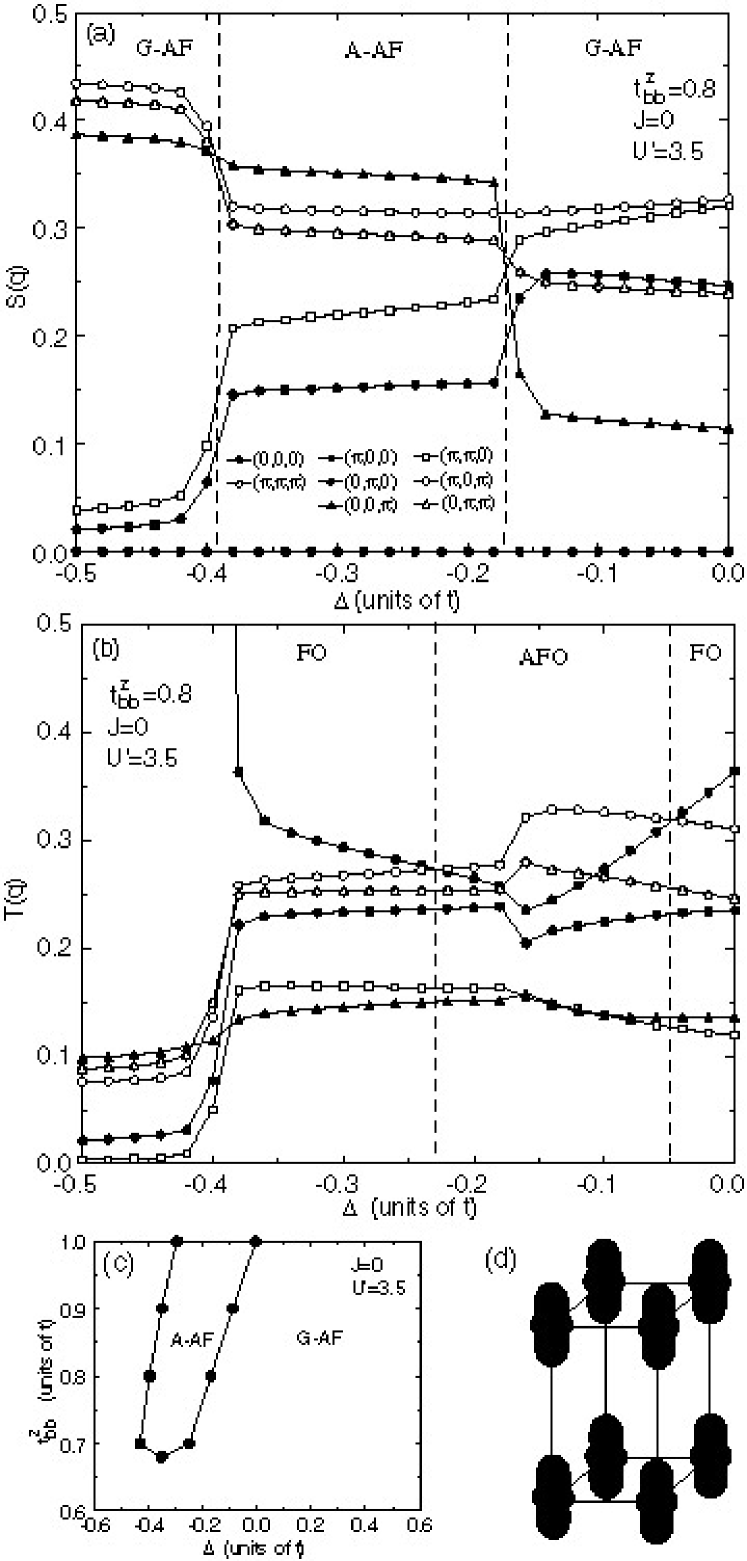
Let us now discuss the reasons for the appearance of an A-AF phase. For negative values of , we easily obtain FO ordering composed of orbitals, as illustrated in Fig. 6(d). For electrons to gain kinetic energy of motion along the -axis, it is necessary to place the AF spin arrangement along this same axis. In the FM spin configuration, electrons cannot move along the -axis due to the Pauli principle, since hopping occurs between orbitals along the -axis. On the other hand, in the plane -orbital electrons can hop to neighboring -orbitals with a significant amplitude, which is larger than that between neighboring -orbitals. Thus, in order to gain kinetic energy, electrons tend to occupy -orbitals even in the FO state composed of -orbitals, as long as is not so large. When we explicitly include the effects of the Hund’s rule interaction , electron spins should have FM alignment between neighboring sites in order to gain energy in hopping processes from - to -orbitals. Consequently, a FM spin configuration is favored in the plane. In fact, in spite of the FO state for 0, we can see a significant component of . In cases with antiferro orbital correlations, spin correlation tends in general to be FM, as has been widely recognized in orbitally degenerate systems.
Here we mention a relation of to the magnetic anisotropy in U-115 materials. For UPtGa5 with the A-AF phase, is larger than , whereas this anisotropy is not pronounced in UNiGa5 with the G-AF phase.U115-8 An analysis for the high-temperature region based on coupling yields the =1/2 Kramers doublet as the ground state among the dectet of =9/2 (=6 and =3/2).Walstedt The states with =1/2 in the coupling scheme have significant overlap with and in the - coupling scheme. Accordingly, by the present definition should be negative to place below . If the absolute value of (0) becomes large, is well separated from and the magnetic anisotropy will consequently become large. Thus, a change from G- to A-type AF phase is consistent with the trends of magnetic anisotropy in UNiGa5 and UPtGa5.
Finally, we make a brief comment about the effect of . Following the above discussion, the A-AF phase should appear even for small . However, in the persent calculation it disappears for 0.68, a critical value which seems to be rather large. Such a quantitative point depends on the system size, and we note that it is necessary to perform the calculation in the thermodynamic limit. This is a problem for future consideration.
IV Discussion and Summary
In this paper, we have proposed a calculational model with active orbital degrees of freedom in an effort to understand the magnetic structure of uranium compounds from a microscopic point of view. In order to construct such a model, we have incorporated the - coupling scheme, in which one-electron states are defined first, and Coulomb interactions are included subsequently. This approach is consistent with the itinerant picture for electrons. By using an exact diagonalization technique, we have found a magnetic metallic phase with antiferro-like orbital correlations for UGa3 and a change in the magnetic structure from G- to A-type AF phases for UMGa5.
In an effort to understand the magnetism and superconductivity of -electron systems from a microscopic standpoint, we have carried out a study of an orbitally degenerate model. While such investigations are just beginning, we already see a number of opportunities for future work along this path. Concerning issues directly related to the present paper, it is highly recommended that calculations be carried out in the thermodynamic limit, in order to confirm the present exact diagonalization results. For instance, the magnetic susceptibility should be evaluated in the random phase approximation or fluctuation-exchange method. With such an approach, the magnetic structure can be discussed by detecting the divergence in the magnetic susceptibility. This is one of our future tasks. Another problem is how to establish the effective reduction of in considering the case of UMGa5. In such systems, MGa2 sheets are interspersed between UGa3 layers, but the main process may occur through the Ga ions.Harima To analyse this, it is necessary to treat a three-dimensional - model with explicit consideration of U and Ga ions. This is another problem for future investigation.
We comment briefly on the CEF levels of 115 compounds. In this paper, we have considered the UMGa5 systems by introducing a splitting energy between orbitals. This procedure did not include changes in the basis wavefunctions. Nonetheless, in following the present strategy, a better way to consider U-115 might be to accommodate three electrons in the CEF levels of Ce-115. Regarding the latter systems, there are some interesting results in the literature. In analyses of the susceptibility and specific heat, Takeuchi ; Shishido for example, the ground level has been considered to be , consistent with in Ce-115, and the first excited level has been suggested to be , not . Regarding CeRhIn5, neutron scattering experiments have been performed in spite of the inclusion of indium, Christiansen identifying energy levels in the sequence , , and , in agreement with previous analyses.Shishido If we simply put three electrons into the CEF levels of CeRhIn5, assuming Hund’s rule coupling to be small, it may be difficult to understand the appearance of A-type AF phases, since becomes positive within the level scheme of Ce-115.
A simple way to understand such a discrepancy is to remark that Ce-115 contains In and M = Co, Ir, and Rh, while the U-115 considered here contains Ga and M = Ni, Pd, and Pt. Different ions lead to different effects on the level scheme. In fact, the magnetic anisotropy of UCoGa5 (Pauli paramagnet) is small compared with that of UNiGa5, and is slightly larger than . In UFeGa5, which is also a Pauli paramagnet, we have found that , opposite to what is observed in UNiGa5 and UPtGa5. We envisage that in UMGa5, is positive for M=Fe, slightly positive for M=Co, and negative for M=Ni. Moreover, increases in the sequence , , and transition metal ions, consistent with the magnetic anisotropy.
In summary, we have analyzed an orbitally degenerate model appropriate for UGa3 and UMGa5 using an exact diagonalization technique. What we have found is a magnetic metallic phase with antiferro-like orbital correlations. By introducing tetragonal effects such as level splitting and a reduced hopping amplitude along -axis, we have reproduced the change in the spin structure from G- to A-type AF phases, corresponding to UNiGa5 and UPtGa5.
Acknowledgement
The author thanks H. Harima for fruitful discussions on the band-structure calculation results for CeIn3 and UGa3. He is also grateful to R. E. Walstedt for valuable comments and critical reading of the manuscript. Stimulating discussions with Y. Haga, S. Ikeda, S. Kambe, K. Kaneko, H. Kato, T. Maehira, T. D. Matsuda, N. Metoki, H. Onishi, Y. Ōnuki, T. Takimoto, and K. Ueda have benefited the present paper. This work has been supported by the Grant-in-Aid for Scientific Research from Japan Society for the Promotion of Science. The computation in this work has been partly done using the facilities of the Supercomputer Center, Institute for Solid State Physics, University of Tokyo
Appendix A Level scheme
In this Appendix, we examine a local -electron state based on the - coupling scheme, comparing it with that obtained from the coupling scheme and from experimental results. Concerning the level scheme for the electron state, we consider two cases.
First, we consider the AuCu3-type cubic crystal structure with one electron per site. As already mentioned in the main text, a typical material is CeIn3, in which and are the ground and first excited states, respectively,Knafo as shown in Fig. 7(a). If we accommodate one more electron to consider the configuration, immediately there appear two possibilities, “low” and “high”-spin states. When the CEF splitting energy between and levels is smaller than the Hund’s rule coupling, the second electron should be accommodated in the levels. In the situation in which one is in the and the other in the , a or triplet appears for the state in general, but under special conditions, a doublet can occur. On the other hand, if the CEF splitting is larger than the Hund’s rule interaction, then the ground state is formed from two electrons, leading to a state. When we compare this state with that in the coupling scheme, we notice that it is given by a mixture of =0 and =4 states, but the =4 component is found to be dominant. Note also that is the antisymmetric representation of .
Since we do not know the exact value of the Hund’s rule interaction in -electron compounds, it is difficult to determine the state by purely theoretical arguments. In this case, we have to refer to data on actual materials. Fortunately, we have the example of PrIn3, a typical material with AuCu3-type crystal structure. From several experimental results, has been confirmed to be the ground level in PrIn3.PrIn3 Thus, the low-spin state should be taken for the AuCu3-type structure in the - coupling scheme.
Here the reader may pose a naive question: Is the Hund’s rule interaction really that small in -electron systems? We have already had to answer this question in a previous paper.Hotta In a word, we are considering the effective Hund’s rule interaction in the - coupling scheme, not in the coupling scheme. The original form for the Hund’s rule interaction is written as , where denotes the operator for the “real” -electron spin at site and is the Hund’s rule interaction among electrons in =3 orbitals. In order to transfer this to the - coupling scheme, it is convenient to use the well-known relation =, where is the Landé’s -factor and is the operator for the total angular momentum of =5/2 at site . From standard textbooks, we easily obtain =6/7, indicating that =. Thus, the Hund’s rule term in the - coupling scheme is rewritten as with =. Note then that the magnitude of the Hund’s rule interaction is effectively reduced by the factor 1/49 in the - coupling scheme. Even if =1eV, is reduced to be about 200K, which is comparable with the CEF splitting energy. Thus, it is possible to have the low-spin state in the - couping scheme.
Next, we take a further step to the state by adding one more electron. Since is fully occupied to form , the next electron should be placed in the state as shown in Fig. 7(c), clearly indicating that there exists an active orbital degree of freedom. The state composed of two and one electron is expressed as in the terminology of group theory. When we again consider actual materials, NdIn3 is found to be a typical material with the AuCu3-type crystal structure. In experiments, it has been established that is the ground level,NdIn3 as we have found with the present - coupling scheme.
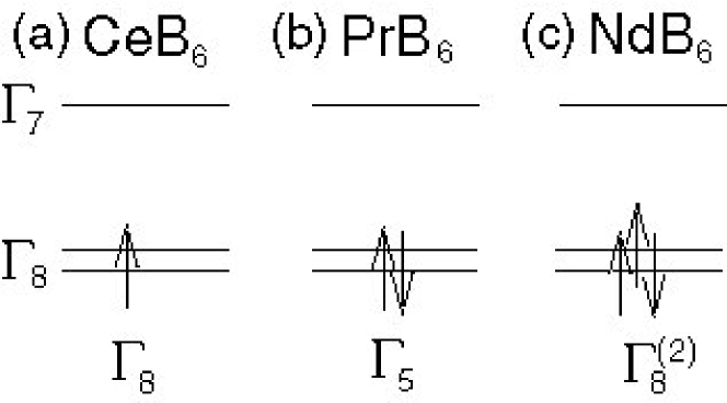
Let us turn our attention to another crystal structure in which is lower than in the configuration. Typical materials are the rare-earth hexaborides RB6 with R=Ce, Pr, and Nd. As is well known, the ground level of CeB6 is , indicating that the quadrupolar degree of freedom plays an active role in this material.CeB6 In fact, anomalous behavior related to quadrupolar ordering has been suggested by several exeprimental results.
First, we note that the level splitting between and is assumed to be larger than the Hund’s rule interaction. When we accommodate two electrons in orbitals, the triplet (), doublet (), and singlet () states are allowed. Among these, owing to the effect of the Hund’s rule interaction, even if it is small, the triplet should be the ground state. This has actually been observed in PrB6.Loewenhaupt ; PrB6 Further, in order to consider NdB6, yet another electron is put into the orbital, making a total of three. Alternatively, we may say that there is one hole in the orbital. Such a state is found, again, to be characterized by . Experimental results on NdB6 have actually been reported which lead to the ground state of .Loewenhaupt ; NdB6 Thus, when is the ground state for the one -electron case, we obtain for the and for the configurations.
We have shown that the ground states deduced from the - couping scheme are consistent with experimental results. However, in order to explain the experimental results quantitatively, it is unavoidable to analyze the CEF levels using the coupling scheme. What we would like to stress is that even in a localized system, the symmetry of the ground level can be understood via the - coupling scheme. We need to recognize the limitations of the - coupling scheme when we treat a local electronic state. For instance, to consider the state, we simply put three electrons into the CEF level scheme which is determined with the configuration. Thus, the wavefunction of the state is uniquely determined. However, in an actual situation, the dectet labelled by =9/2 (=6 and =3/2) is split into two and one orbital. The ground-state wavefunctions will then depend on the two CEF parameters and .LLW As mentioned above, in order to explain experimental results on localized -electron materials, ones should analyze the CEF effects in the system using the coupling scheme. In this paper, however, the electronic states are considered with an itinerant picture based on the - coupling scheme. Thus, it is important to check that the local electronic state formed by electrons in this way is consistent with the symmetry of the state obtained with the coupling scheme.
In summary, it has been shown that the ground states of the and configurations can be qualitatively reproduced by accommodating electrons in the CEF levels of a corresponding material, provided that the CEF level splitting is larger than the Hund’s rule interaction. Thus, the - coupling scheme works even in the localized case. Accordingly, we believe that a microscopic theory can be developed in which we discuss the magnetism and superconductivity of -electron compounds in terms of the - coupling scheme.
References
- (1) Y. N. Grin, P. Rogl, and K. Hiebl, J. Less-Common Met. 121, 497 (1986).
- (2) Y. Ōnuki, D. Aoki, P. Wiśnieski, H. Shishido, S. Ikeda, Y. Inada, R. Settai, Y. Tokiwa, E. Yamamoto, Y. Haga, T. Maehira, H. Harima, M. Higuchi, A. Hasegwa, and H. Yamagami, Acta Phys. Pol. B32, 3273 (2001).
- (3) Y. Tokiwa, Y. Haga, E. Yamamoto, D. Aoki, N. Watanabe, R. Settai, T. Inoue, K. Kindo, H. Harima, and Y. Ōnuki, J. Phys. Soc. Jpn. 70, 1744 (2001).
- (4) Y. Tokiwa, T. Maehira, S. Ikeda, Y. Haga, E. Yamamoto, A. Nakamura, Y. Ōnuki, M. Higuchi, and A. Hasegawa, J. Phys. Soc. Jpn. 70, 2982 (2001).
- (5) Y. Tokiwa, Y. Haga, N. Metoki, Y. Ishii, and Y. Ōnuki, J. Phys. Soc. Jpn. 71, 725 (2002).
- (6) Y. Tokiwa, S. Ikeda, Y. Haga, T. Ōkubo, T. Iizuka, K. Sugiyama, A. Nakamura, Y. Ōnuki, J. Phys. Soc. Jpn. 71, 845 (2002).
- (7) H. Kato, H. Sakai, Y. Tokiwa, S. Kambe, R. E. Walstedt, and Y. Ōnuki, J. Phys. Chem. Solids 63, 1197 (2002).
- (8) S. Ikeda, Y. Tokiwa, Y. Haga, E. Yamamoto, T. Ōkubo, M. Yamada, N. Nakamura, K. Sugiyama, K. Kindo, Y. Inada, H. Yamagami, and Y. Ōnuki, J. Phys. Soc. Jpn. 72, 576 (2003).
- (9) K. Kaneko, N. Metoki, N. Bernhoeft, G. H. Lander, Y. Ishii, S. Ikeda, Y. Tokiwa, Y. Haga, and Y. Ōnuki, Phys. Rev. B 68, 214419 (2003).
- (10) Here we follow the definitions of spin structure in E. O. Wollan and W. C. Koehler, Phys. Rev. 100, 545 (1955).
- (11) See, for instance, P. Dervenagas, D. Kaczorowski, F. Bourdarot, P. Burlet, A. Czopnik, and G. H. Lander, Physica B 269, 368 (1999).
- (12) D. Mannix, A. Stunault, N. Bernhoeft, L. Paolasini, G. H. Lander, C. Vettier, F. de Bergevin, D. Kaczorowski, and A. Czopnik, Phys. Rev. Lett. 86, 4128 (2001).
- (13) T. Hotta and K. Ueda, Phys. Rev. B67, 104518 (2003).
- (14) M. T. Hutchings, Solid State Phys. 16, 227 (1965).
- (15) W. Knafo, S. Raymond, B. Fak, G. Lapertot, P. C. Canfield, and J. Flouquet, J. Phys.: Condens. Matter 15, 3741 (2003).
- (16) K. Betsuyaku and H. Harima, to appear in J. Magn. Magn. Mater.
- (17) H. Harima, private communications.
- (18) T. Hotta, A. L. Malvezzi, and E. Dagotto, Phys. Rev. B62, 9532 (2000). See also E. Dagotto, T. Hotta, and A. Moreo, Phys. Rep. 344, 1 (2001).
- (19) Y. Ōnuki, Y. Haga, E, Yamamoto, Y. Inada, R. Settai, H. Yamagami, and H. Harima, J. Phys.: Condens. Matter 15, S1903 (2003).
- (20) D. Aoki, N. Suzuki, K. Miyake, Y. Inada, R. Settai, K. Sugiyama, E. Yamamoto, Y. Haga, Y. Ōnuki, T. Inoue, K. Kindo, H. Sugawara, H. Sato, and H. Yamagami, J. Phys. Soc. Jpn. 70, 538 (2001).
- (21) Y. Haga, F. Honda, T. Eto, G. Oomi, T. Kagayama, N, Takeshita, N. Mri, T. Nakanishi, Y. Tokiwa, D. Aoki, and Y. Ōnuki, J. Phys. Soc. Jpn. 71, 2019 (2002).
- (22) T. Hotta, M. Moraghebi, A. Feiguin, A. Moreo, S. Yunoki, and E. Dagotto, Phys. Rev. Lett. 90, 247203 (2003); T. Hotta, Phys. Rev. B67, 104428 (2003).
- (23) R. E. Walstedt, private communications.
- (24) T. Takeuchi, T. Inoue, K. Sugiyama, D. Aoki, Y. Tokiwa, Y. Haga, K. Kindo, and Y. Ōnuki, J. Phys. Soc. Jpn. 70, 877 (2001).
- (25) H. Shishido, R. Settai, D. Aoki, S. Ikeda, H. Nakawaki, N. Nakamura, T. Iizuka, Y. Inada, K. Sugiyama, T. Takeuchi, K. Kindo, T. C. Kobayashi, Y. Haga, H. Harima, Y. Aoki, T. Namiki, H. Sato, and Y. Ōnuki, J. Phys. Soc. Jpn. 71, 162 (2002).
- (26) A. D. Christianson, J. M. Lawrence, P. G. Pagliuso, N. O. Moreno, J. L. Sarrao, J. D. Thompson, P. S. Riseborough, S. Kern, E. A. Coremychkin, and A. H. Lacerda, Phys. Rev. B 66, 193102 (2002).
- (27) K. H. J. Buschow, H. W. de Wijn, and A. M. van Diepen, J. Chem. Phys. 50, 137 (1969); W. Gro, K. Knorr, A. P. Murani, and K. H. J. Buschow, in Crystal Field Effects in Metals and Alloys, ed. A. Furrer (Plenum, New York, 1977) p. 37.
- (28) A. Czopnik, J. Kowalewski, and M. Hackemer, Phys. Status Solidi A 127, 243 (1991); M. Amara, P. Morin, and J. Rouchy, J. Magn. Magn. Mater. 130, 115 (1994); M. Amara, R. M. Galéra, P. Morin, T. Veres, and P. Burlet, ibid. 130, 127 (1994).
- (29) M. Sera and S. Kobayashi, J. Phys. Soc. Jpn. 68, 664 (1999) and references therein.
- (30) M. Loewenhaupt and M. Prager, Z. Phys. B 62, 195 (1986).
- (31) S. Kobayashi, M. Sera, M. Hiroi, T. Nishizaki, N. Kobayashi, and S. Kunii, J. Phys. Soc. Jpn. 70, 1721 (2001).
- (32) G. Pofahl, E. Zirngiebl, S. Blumenröder, H. Brenten, G. Güntherodt, and K. Winzer, Z. Phys. B 66, 339 (1987); G. Uimin and W. Brenig, Phys. Rev. B 61, 60 (2000); K. Kubo and Y. Kuramoto, J. Phys.: Condens. Matter 15, S2251 (2003).
- (33) K. R. Lea, M. J. M. Leask, and W. P. Wolf, J. Phys. Chem. Solids 23, 1381 (1962).