In-situ diagnostics of the crystalline nature of single organic nanocrystals by nonlinear microscopy
Abstract
We elucidate the crystalline nature and the three-dimensional orientation of isolated organic nanocrystals embedded in a sol-gel matrix, using a polarized nonlinear microscopy technique that combines two-photon fluorescence and second harmonic generation. This technique allows the distinction between mono-crystalline structures and nano-scale poly-crystalline aggregates responsible for incoherent second harmonic signals.
pacs:
78.67.Bf, 42.65.-k, 61.82.RxThe optical properties of nanoparticles have recently attracted much attention. In addition to metallic and semiconductor nanoparticles which are now used as bio-markers and as the building blocks of nanostructured materials NanopartBio , their organic counterparts constitute an interesting alternative. Advances in molecular engineering have enabled the design of molecular structures of various resonances and symmetries with optimized one- and two-photon absorption cross sections 2PhotonDyes , or combining different optical properties such as luminescence and second harmonic generation (SHG) Blanchard . In addition, macroscopic molecular arrangements have been optimized using the tensorial oriented gas model NLOcrystals , which predicts that an enhancement of the SHG efficiency is expected from the non-centrosymmetric crystalline arrangement of efficient nonlinear molecules. Molecular nanocrystals can be therefore envisioned as a new class of multi-functional nano-scale materials. In the case of organic nanocrystals however, the traditional crystalline characterization techniques have raised many practical barriers due to their low concentration and fragility. Consequently, the elucidation of their crystalline nature has been so far indirect or averaged over a large number of nanocrystals Vallee .
In this letter, we show that two-photon nonlinear microscopy permits in-situ characterization of isolated organic nanocrystals grown in an amorphous sol-gel matrix. The diagnostic is based on polarization resolved two-photon excited fluorescence (TPF) and SHG. TPF is an incoherent process allowed in centrosymmetric media, which exhibits a specific anisotropy depending on the medium symmetry. On the other hand, SHG is the signature of a crystalline non-centrosymmetric phase in the sample, with a sensitivity down to the nanometric scale NLO-LB ; PrasadNanoCrystals . We show that the polarization analysis of both TPF and SHG from nanocrystals allows the unambiguous discrimination between isolated mono-crystalline and poly-crystalline systems. Moreover, once a nanocrystal has been identified as mono-crystalline, a detailed model for both TPF and SHG polarization responses accounting for the unit-cell symmetry allows the determination of its three-dimensional orientation within the host matrix.
The organic nanocrystals that we investigate are based upon the -((4’-methoxyphenyl)methylene)-4-nitro-benzene-acetonitrile) molecule (CMONS), which exhibits efficient luminescence and quadratic nonlinearity under two-photon excitation Wang ; Treussart ; Sanz . The bulk crystalline phases of such crystals have three possible polymorphic forms, two being non-centrosymmetric with a very similar unit-cell crystal geometry (forms and )Sanz ; CMONScristallo ; Oliver . The preparation of the organic nanocrystals in sol-gel glasses relies on the control of the nucleation and growth kinetics of the dye confined in the pores of the gel Sanz . CMONS nanocrystals were grown in 1:1 tetramethoxysilane(TMOS):methyltrimethoxysilane(MTMOS) matrices with a controlled CMONS:alkoxydes molar fraction. The sols containing the alkoxyde solvent, water and organic phases are directly spin-coated on a glass substrate. The presence of nanocrystals in the sol-gel film after spin-coating was ascertained by measurement of the material melting point using differential scanning calorimetry. Previous works on such materials have shown through bulk spectroscopy characterizations that the nanocrystals are in the predominant thermodynamically stable form, with a luminescence maximum peaking around 500-580 nm Sanz . The particle mean size, which depends on the preparation parameters such as temperature and matrix porosity, ranges from 20 to 100 nm. In this work, we focus on the smallest particles, which are obtained using a CMONS:alkoxydes molar fraction of .
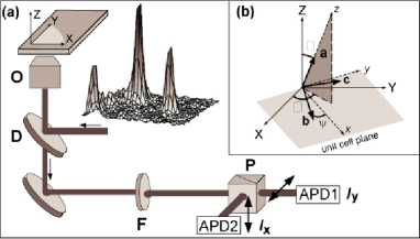
CMONS nanocrystals immobilized in the sol-gel film (0.5 - 1 m thickness) are imaged using an inverted two-photon microscopy set-up with an excitation wavelength of 987 nm from a Ti:Sa laser (150 fs pulses duration, 82 MHz repetition rate) LeFloch . The reflection geometry, which uses a dichroic mirror to provide the incident IR light onto the sample, is well suited for the observation of SHG from structures of sub-wavelength size, this optical process being in this case insensitive to nonlinear phase-mismatch effects. The SHG signal, at half of the incident wavelength (493.5 nm), is spectrally shifted from the TPF emission maximum (at around 570 nm in the studied films), and can therefore be detected separately using appropriate spectral filters 111Note that for all quantitative analysis, we account for residual TPF emission in the SHG detection channel.. TPF and SHG scanning microscopy images exhibit isolated spots (about per 10 m2) with diffraction limited resolution (Fig. 1(a)). The polarized two-photon microscopy technique consists of rotating the incident IR linear polarization while recording the SHG or TPF signals along two perpendicular ( and ) polarization directions for each isolated nanocrystal. We will show that this simple scheme allows the distinction between mono-crystalline and poly-crystalline forms.
In order to model the polarization responses of both optical processes, we first assume a mono-crystalline CMONS nanocrystal whose unit-cell orientation is defined by the Euler set of angles , as illustrated in Fig. 1(b).
The CMONS crystalline unit-cell in its non-centrosymmetric form is represented in Fig. 2. The unit-cell is composed of four CMONS molecules arranged according to the monoclinic crystalline space group CMONScristallo . The macroscopic polarization responses from mono-crystalline nanocrystals are dependent on their unit-cell orientation . The TPF optical response involves the molecular fourth order and second order susceptibility tensors, which participate respectively to the two-photon absorption and the one-photon emission processes. The TPF intensity analyzed in the polarization direction is proportional to LeFloch :
| (1) |
where the indexes span the macroscopic frame (), and denotes photodetection temporal averaging. The components are the incident field polarization projections on each macroscopic axis. The SHG optical response stems from the molecular third order susceptibility tensor. The resulting intensity analyzed in the polarization direction for a mono-crystalline structure originates from the coherent addition of induced nonlinear polarizations from each molecule in the crystal, and is therefore proportional to:
| (2) |
Using Eqs. (1), (2) and in-plane rotation of the incident polarization, each of the macroscopic coefficients , and can be deduced. These coefficients depend on the orientation angle and on the unit-cell susceptibility components , and with (a,b,c). For any tensor with components expressed in the macroscopic frame, the dependence of these coefficients can be readily calculated from a projection law , where the functions of () express the unit-cell frame projection in the macroscopic frame. Consequently, the exploration of polarization responses finally relies on the knowledge of the microscopic and tensor coefficients for TPF detection, and of the tensor coefficients for SHG. At the molecular scale, we modelled a single CMONS molecule by a rod-like system of susceptibility components denoted , and , defining the CMONS fundamental dipole direction in the molecular frame Wang . The unit-cell tensor coefficients are constructed from the addition of each molecular contribution accounting for their respective orientation in the unit cell, according to the oriented gas model. This model neglects possible contributions from intermolecular interactions in the susceptibility calculations NLOcrystals . Numerical values of the resulting , and tensor coefficients in the unit-cell (a,b,c) frame are given in the table of Fig. 2, the few non-vanishing remaining coefficients being consistent with the unit-cell symmetry. The off-diagonal tensor coefficients are the signature of the multipolar symmetry of the CMONS nanocrystals, which strongly influences the polarization dependence of the macroscopic optical responses.
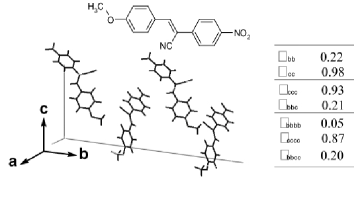
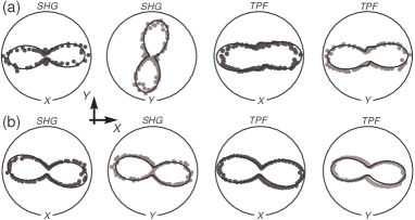
Fig. 3 shows a typical example of signals from two isolated nanocrystals, exhibiting various TPF and SHG polarization responses analyzed in the and directions. These signals can be simultaneously fitted with the previous model, which is a clear evidence of mono-crystalline structures. Moreover, the fit of both TPF and SHG features permits the retrieval of the orientation parameters of such nanocrystals, using Eqs (1) and (2) 222The fits account for the large aperture of the microscope objective, as well as the slight ellipticity and dichroism resulting from reflection of the incident IR beam on the dichroic mirror, characterized separately by ellipsometry.. This example shows a typical situation where two nanocrystals of different orientations exhibit similar TPF polarization responses, with on the contrary very different SHG responses. This originates from the distinct tensorial nature of these two optical processes: TPF involves even order tensors and is sensitive to the axial order terms of the molecular distribution (symmetric contributions), whereas SHG is sensitive to odd order parameters (non-centrosymmetric contributions). This complementarity is therefore the key point in the determination of the 3D orientation of isolated nanocrystals 333The 3D orientation determination would however not be possible in the rare case of rod-like symmetry () crystals, for which the projection of the unit-cell in the sample plane is of the same symmetry as the system itself.. In comparison, traditional fluorescence microscopy only measures the in-plane orientation of the emitters, while the access to out-of plane contributions requires the use of complex optical field geometries or variable incident angle measurements SingleMolecule ; Wild .
In the present measurements, the determination of the three () angles is furthermore unambiguous. Indeed, a slight change of one of the three Euler angles (by typically ) would clearly modify differently the TPF and SHG polarization responses. Moreover another type of analysis, which consists of using the experimental TPF and SHG anisotropy ratios in order to determine the unit-cell orientation, gives similar results by ruling-out any solution that does not correspond to polar plots such as those shown in Fig. 3.
It is visible from the measurements on mono-crystalline structures of Fig. 3 that the TPF polarization responses in the and analysis directions have the same shape, although they are of different amplitudes. This effect is also predicted mathematically by the model. A departure from this main characteristic is therefore evidence of a non mono-crystalline phase which contains at least two or more nanocrystals. Such behavior, as represented in Fig. 4, is typically observed for about 30% of the measured nanocrystals. The TPF and SHG features of Fig. 4(a) are identical and have a () axial symmetry for crossed polarization excitations. Such symmetry, fixed by the detection polarization directions, is a signature of incoherent emission from an isotropic orientational distribution of emitters. This effect, which has been observed in Rayleigh scattering experiments in solutions HLS , has been only moderately investigated so far in the study of nanoparticles NLOgold . In the case of the CMONS nanoparticles, an incoherent SHG emission is made possible by their sub-wavelength size, contrary to micrometer-scale particles for which the SHG efficiency is expected to depend strongly on the particle size when it approaches the coherence length. Such an effect can occur from the nano-scale assembly of randomly oriented SHG-active nanocrystals formed during the crystallization process. An incoherent summation of the responses from nanocrystals of different orientations contained in a sub-wavelength size aggregate can be modelled by the following SHG or TPF intensities:
| (3) |
with being the SHG or TPF intensities from a nanocrystal of given orientation in the aggregate.

Computing the SHG and TPF responses with an increasing amount of randomly generated orientations, the completely symmetric features of Fig. 4(a) start appearing from an incoherent summation over nanocrystals. Less-symmetric features are the signature of an intermediate situation between mono-crystalline and isotropic assemblies of nanocrystals originating from a sum over 2 to 10 nanocrystals. In Fig. 4(b), a reasonable fit is obtained for = nanocrystals in the aggregate, having different relative orientations. Our observations therefore allow the distinction between mono-crystalline and more complex poly-crystalline structures formed by either a nearly-isotropic aggregate of nanocrystals, or by a small number ( for the current analysis) of nanocrystals with sub-wavelength sizes.
In conclusion, the combination of TPF and SHG in two-photon nonlinear polarized microscopy has allowed the examination of organic nanoparticles, with the possibility to clearly distinguish mono-crystalline structures from poly-crystalline arrangements. We have also shown that a quantitative model of the TPF and SHG polarization responses enables the 3D orientation of mono-crystalline nanocrystals imbedded in an amorphous host matrix. This method can be extended to a broad variety of complex structures. The study of both polarized SHG and TPF at the nanoscale level can be applied to investigate local field effects and local orientation of molecules under electrical or optical fields perturbation. It can furthermore be extended to orientational tracking of optical markers in complex environments.
The authors thank Pr. J.-F. Nicoud (IPCMS Strasbourg) for his assistance in the selection and preparation of the chromophore, V. De Beaucoudrey for experimental contributions, and R. Pansu for fruitful discussions. This work is partially supported by an ACI ”Jeune Chercheur” grant from Ministère de la Recherche, France.
References
- (1) C.M. Niemeyer, Angew.Chem. Int. Ed. 40, 4128 (2001).
- (2) M. Albota, D. Beljonne, J.-L. Brédas, J.E. Ehrlich, J.-Y. Fu, A. A. Heikal, S.E. Hess, T. Kogej, M. D. Levin, S.R. Marder, D. McCord-Maughon, J.W. Perry, H. Röckel, M. Rumi, G. Subramaniam, W.W. Webb, X.-L. Wu and C. Xu, Science 281, 1653 (1998).
- (3) L. Ventelon, L. Moreaux, J. Mertz and M. Blanchard-Desce, Synth. Met. 127, 17 (2002).
- (4) J. Zyss and J.L. Oudar, Phys. Rev. A 26, 2028 (1982).
- (5) R. Vallée, P. Damman, M. Dosière, E. Toussaere and J. Zyss, Jour. Am. Chem. Soc. 122, 6701 (2000).
- (6) C.K. Chen, T.F. Heinz, D. Ricard and Y.R. Shen, Phys. Rev. lett. 46, 1010 (1981).
- (7) Y. Shen, J. Swiatkiewicz, J. Winiarz, P. Markowicz and P.N. Prasad, Appl. Phys. Lett. 77, 2946 (2000).
- (8) Y. Wang, W. Tam, S.M. Stevenson, R.A. Clement and J. Calabrese, Chem. Phys. Lett. 148, 136 (1998).
- (9) F. Treussart, E. Botzung-Appert, N.T. Ha-Duong, A. Ibanez, J.-F. Roch and R. Pansu, Chem. Phys. Chem. 4,757 (2003).
- (10) N. Sanz, P.L. Baldeck, J.F. Nicoud, Y. LeFur and A. Ibanez, Solid State Sciences 3, 867 (2001).
- (11) R.M. Vrcelj, E.E.A. Shepderd, C.Y. Yoon, J. Sherwood and A.R. Kennedy, Crystal Growth and Design 2, 609 (2002).
- (12) S.N. Oliver, P. Pantelis and P.L. Dunn, Appl. Phys. Lett. 56, 307 (1990).
- (13) V. Le Floc’h, S. Brasselet, J.-F. Roch and J. Zyss, to be published in J. Phys. Chem. B., arXiv cond-mat/030778 (2003).
- (14) M. Vacha and M. Kotaki, J. Chem. Phys. 118, 5279 (2003).
- (15) M. Prummer, B. Sick, B. Hecht and U. Wild, J. Chem. Phys. 118, 9824 (2003).
- (16) R.W. Terhune, P.D. Maker and S.M. Savage, Phys. Rev. Lett. 14, 681 (1965).
- (17) M.L. Sandrock, C.D. Pibel, F.M. Geiger and C.A. Foss, J. Chem. Phys. 103, 2668 (1999).