Quantum Hall Effect in a Two-Dimensional Electron System Bent by 90∘
Abstract
Using a new MBE growth technique, we fabricate a two-dimensional electron system which is bent around an atomically sharp 90∘ corner. In the quantum Hall regime under tilted magnetic fields, we can measure equilibration between both co- and counter-propagating edge channels of arbitrary filling factor ratio. We present here 4-point magnetotransport characterization of the corner junction with filling factor combinations which can all be explained using the standard Landauer-Büttiker edge channel picture. The success of this description confirms the realization of the first non-planar quantum Hall edge geometry.
keywords:
Quantum Hall effect , edge states , co-propagating , counter-propagating , corner quantum wellPACS:
72.20.My , 72.15.Gd , 73.40.Lq , 73.40.Hm, , , , , , and
1 Introduction
In the quantized Hall regime, a clean two-dimensional electron system (2DES) with electron density in the presence of a magnetic field exhibits quantized steps in the Hall resistance near values of magnetic field where the filling factor, is an integer or odd-denominator fraction, describing the integer [1] or fractional [2] quantum Hall effect, respectively. These steps result from a mobility gap in the bulk region, leaving gapless edge modes responsible for describing current conduction in the system [3]. Early [4, 5, 6, 7] and recent [8, 9] experiments on the quantum Hall effect tested the equilibration properties of edge channels in gated structures that populate different channels at different chemical potentials. However, the reduced mobility of low-density gated regions restricts the filling factor combinations that can be tested, and in planar structures co- and counterpropagating equilibration studies require fundamentally different gate designs [8, 9]. We present in this paper a new type of device for studying edge state equilibration which permits abrupt junctions between arbitrary filling factors of both co- and counter-propagating edges, simply by tilting the sample in a magnetic field.
2 Sample
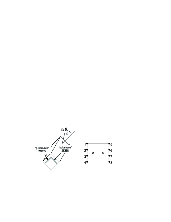
We call our device the corner-quantum well heterojunction (CQW), fabricated by overgrowing a standard GaAs/AlGaAs heterojunction structure on a precleaved corner [10] as depicted schematically in Fig. 1, left. The length of the corner junction in the data presented here is 3.2 mm, and indium contacts are alloyed to each facet away from the corner junction, and indexed as shown in the top perspective of Fig. 1, right. We identify one side of the device as the ’substrate’ (s), and the other side as the ’precleave’ (p) as in Fig. 1 [10], and measure slightly different electron densities for the two facets under different cool-downs as listed in the captions of Fig. 2 and Fig. 3. We designate the contact configuration of all 4-point resistance measurements with the notation for current leads and voltage measured between .
3 Results
In the presence of a tilted magnetic field at an angle relative to the substrate normal (Fig. 1, left) the relative filling factor between the two systems can be tuned according to:
| (1) |
The high quality of the growth is demonstrated by fractional quantum Hall effect (FQHE) minima appearing on both facets below 1 K. For angles the edge channels counter-propagate at the corner reminiscent of the coupling chirality between gated QHE regions in standard planar structures. But for , the normal component of the magnetic field changes sign across the junction, resulting in a junction of co-propagating edge states of arbitrary filling factor simply by tilting the junction in a B-field.
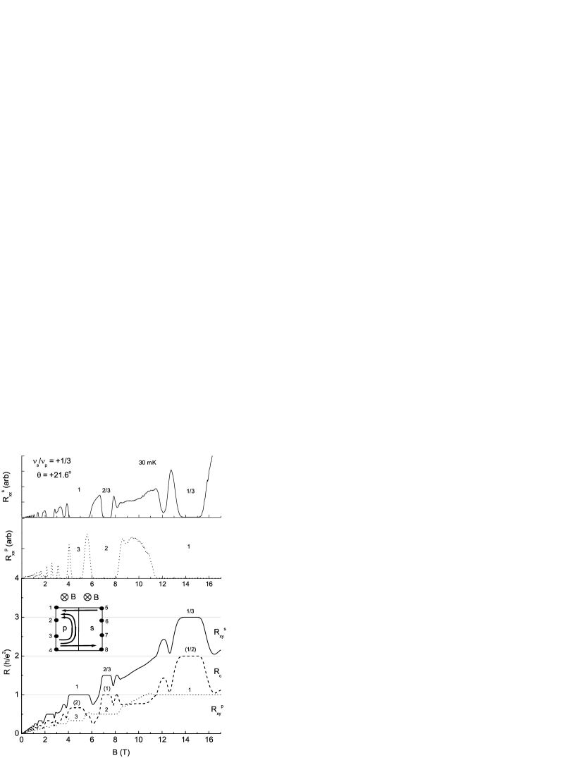
We begin our Hall measurements in the regime. Fig. 2, top, shows and for , corresponding to a magnetic field tilt angle of . The minimae of the series (1:3), , go to zero for both traces, validating the use of the edge channel picture at these fields. The inset of Fig. 2 shows a cartoon of the (1:3) case, showing the sign of the normal -field component in each region. In Fig. 2, bottom, and are plotted along with the 4-point corner resistance . Because current contact number 2 feeds both voltage contacts 4 and 8, the 4-point resistance is trivially zero. By inspection then, is just the difference between the two Hall resistances, confirming the Landauer-Büttiker picture [11] with full equilibration of edge channels on reaching contact 1.
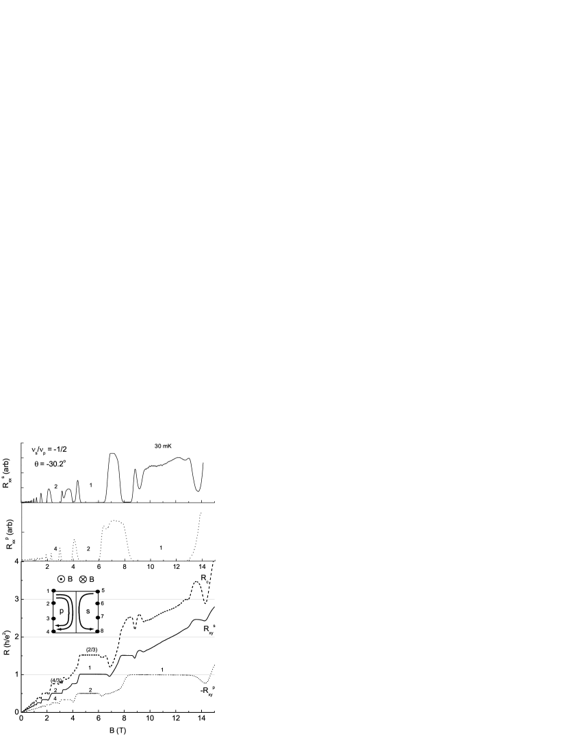
Next we examine , the condition novel to this paper where the normal magnetic field changes sign across the junction, and the edge channel in the precleave system correspondingly switches chirality (Fig. 3, inset). Fig. 3, top, shows and for , corresponding to a -field tilt angle of . There we see well-developed minimae at (2:4) and (1:2). In this novel geometry, the co-propagating edge channels at the mm long corner fully equilibrate, meaning the downstream potential at contacts 4 and 8 are equal and . Correspondingly, the only non-trivial 4-point resistance is again . With the opposite chirality in the two systems, we note that since has changed polarity is now the sum of the individual ’s: . It is worth noting that in planar gate defined geometries, no 4-point resistance can be larger than the largest individual , so we have successfully demonstrated a new regime of validity for the Landauer-Büttiker formalism.
It remains to be seen what physics will be observed at junction lengths of order the interchannel equilibration length, where outgoing channels from the corner are not fully equilibrated, but rather partially reflected/transmitted. In such a case, dependences on co- versus counter-propagation as well as on the specific value are anticipated, and at a lossless junction, novel effects like a dc step-up transformer are predicted, due to Andreev-like quasiparticle reflection [12, 13, 14]. Future experiments with small junctions can also measure interchannel equilibration lengths for both co- and counterpropagating edges in the same device.
4 Conclusion
In conclusion, we observe quantum Hall effect in a new corner quantum well structure. The relative filling factor between 2DEGs on the two facets of the corner is tunable by tilting the magnetic field angle, and two different regimes are studied where the edge channels at the corner junction are co- and counter-propagating. This paper determines that the device functions as expected, and is well behaved in the quantum Hall regime.
References
- [1] K. von Klitzing, G. Dorda, and M. Pepper Phys. Rev. Lett. 45, 494 (1980).
- [2] D. C. Tsui, H. L. Stormer, and A. C. Gossard Phys. Rev. Lett. 48, 1559 (1982).
- [3] B. I. Halperin, Phys. Rev. B 25, 2185 (1982).
- [4] R. J. Haug, A. H. MacDonald, P. Streda, and K. von Klitzing, Phys. Rev. Lett. 61, 2797 (1988).
- [5] B. J. van Wees, E. M. M. Willems, C. J. P. M. Harmans, C. W. J. Beenaker, H. van Houten, J. G. Williamson, C. T. Foxon, and J. J. Harris, Phys. Rev. Lett. 62, 1181 (1989).
- [6] A. M. Chang, and J. E. Cunningham, Sol. State Comm. 72, 651 (1989).
- [7] L.P. Kouwenhoven, B. J. van Wees, N. C. van der Vaart, C. J. P. M. Harmans, C. E. Timmering, and C. T. Foxon, Phys. Rev. Lett. 64, 685, (1990).
- [8] A. Würtz, R. Wildfeuer, A. Lorke, E. V. Deviatov, and V. T. Dolgopolov, Phys. Rev. B 65, 075303 (2002);
- [9] E. V. Deviatov, A. Würtz, A. Lorke, M. Yu. Melnikov, V. T. Dolgopolov, D. Reuter, and A. D. Wieck, cond-mat/0303498 (2003).
- [10] M. Grayson, D. Schuh, M. Huber, M. Bichler, and G. Abstreiter, submitted to Appl. Phys. Lett.
- [11] M. Büttiker, Phys. Rev. Lett. 57, 1761 (1986).
- [12] I. Safi, and H. J. Schulz, Phys. Rev. B R17040 (1995).
- [13] D. B. Chklovskii, and B. I. Halperin, Phys. Rev. B 57, 3681 (1998).
- [14] N. P. Sandler, C. de C. Chamon, and E. Fradkin, Phys. Rev. B 57, 12324 (1998).