Expansion of a Bose-Einstein condensate formed on a joint harmonic and one-dimensional optical-lattice potentials
Abstract
We study the expansion of a Bose-Einstein condensate trapped in a combined optical-lattice and axially-symmetric harmonic potentials using the numerical solution of the mean-field Gross-Pitaevskii equation. First, we consider the expansion of such a condensate under the action of the optical-lattice potential alone. In this case the result of numerical simulation for the axial and radial sizes during expansion is in agreement with two experiments by Morsch et al. [2002 Phys. Rev. A 66 021601(R) and 2003 Laser Phys. 13 594]. Finally, we consider the expansion under the action of the harmonic potential alone. In this case the oscillation and the disappearance and revival of the resultant interference pattern is in agreement with the experiment by Müller et al. [2003 J. Opt. B: Quantum Semiclass. Opt. 5 538].
1 Introduction
The experimental loading of a cigar-shaped Bose-Einstein condensate (BEC) in both one- [1, 2] and three-dimensional [3] optical lattice potentials generated by standing-wave laser fields has initiated a new class of investigations. The optical-lattice potential has been used in the study of matter-wave interference [1], of oscillating atomic current in a one dimensional array of Josephson junctions [4, 5], of Bloch oscillation and Landau Zenner tunneling [6], of superfluid-insulator classical [7] and quantum [3] phase transitions, and in the generation of matter-wave bright soliton [8].
As the size of the condensates in above experiments is much too small, one may resort to an expansion in order to photograph, observe or study it. Actually, expansion of the condensate formed on an optical lattice was crucial in the confirmation of Josephson oscillation across an array of one-dimensional junctions [4], of Bloch oscillation and Landau-Zenner tunneling [6], of superfluid to Mott insulator quantum phase transition [3], and of transition from superfluid to a classical insulator [7, 9]. Hence it is of interest to perform a theoretical study of the expansion of the BEC formed on a joint one-dimensional optical-lattice and axially-symmetric harmonic traps upon the removal of either trap and compare with available experiments [10, 11, 12]. Here we undertake this study using the mean-field axially-symmetric Gross-Pitaevskii (GP) equation [13]. There have been similar studies of free expansion of an axially-symmetric BEC in the absence of an optical-lattice potential [14].
For the present study we consider the expansion of a BEC on a joint one-dimensional optical-lattice and axially-symmetric harmonic potentials with the optical-lattice aligned along the axial direction of the harmonic potential. First we consider switching off the harmonic trap alone. In this case the condensate expands along the radial direction maintaining an almost constant transverse size. We also reconsider the free expansion of such a BEC formed in the absence of an optical-lattice potential. In both cases the time evolution of the half-width of a Gaussian fit to the density profile in the axial and radial directions are obtained and found to be in good agreement with experiments by Morsch et al. [10, 11]. Next we consider switching off the optical-lattice trap alone. The periodic one-dimensional optical-lattice potential divides the whole BEC in parallel slices. Upon the removal of the optical-lattice trap these slices expand and interfere with each other. The result is the formation of an interference pattern of three peaks. However, in the presence of the harmonic trap the side peaks execute simple-harmonic oscillation with a definite frequency and amplitude. If the interference pattern is allowed to evolve in the harmonic trap for some hold time and the harmonic trap is then switched off, prominent interference pattern continues for small hold time. With the increase of hold time the interference pattern disappears and revives periodically. In this case the results of the simulation is in agreement with experiment of Müller et al. [12].
In section 2 we present our mean-field model based on the GP equation. In section 3 we present the numerical results and a comparison with available experiments. Finally, the conclusions are given in section 4.
2 Mean-Field Model
We base the present study on the numerical solution of the time-dependent GP equation [13] in the presence of a combined axially-symmetric harmonic and optical-potential traps. The time-dependent BEC wave function at position and time is described by the following mean-field nonlinear GP equation [13]
| (1) |
where is the mass and the number of atoms in the condensate, with the Planck’s constant, the strength of atomic interaction, the scattering length. In the presence of the combined harmonic and optical traps where is the angular frequency of the harmonic trap in the radial direction , that in the axial direction , and is the optical-lattice trap introduced later. The normalization condition is
In the axially-symmetric configuration, the wave function can be written as . Now transforming to dimensionless variables , , , and (1) becomes [15]
| (2) | |||||
where nonlinearity . In terms of the one-dimensional probability
| (3) |
the normalization of the wave function is given by The probability is useful in the study of the present problem under the action of the optical-lattice potential, specially in the investigation of the formation and evolution of the interference pattern after the removal of the trapping potential(s).
The mean-field GP equation (1) can be derived for a dilute and weakly-interacting system. This is based on the condition that the scattering length be much smaller than the average distance between atoms and . Hence, the dilute gas approximation can be written as [13], where is the average density of the gas. However, for a simple and practical estimate of the weakly interacting condition one should compare the interaction energy with the kinetic energy of the system . From theoretical consideration it follows that [13]
| (4) |
The GP equation is valid for small . Systematic previous studies have shown this equation to be valid for as large as several hundreds [13] and the domain of the experiments of [10, 11, 12] is well within this limit.
In the experiments of [10, 11, 12] a completely asymmetric trap is employed with trapping frequencies in three perpendicular directions , and taken in the ratio 2:1:. An analysis of the experiments using such a fully asymmetric trap is beyond present numerical possibilities. However, in the experiment only a section of the condensate is observed in one of the -, -, or - planes, e.g., the - plane. The optical-lattice potential is set in one of the in-plane directions, e.g., the direction. To make the problem numerically tractable, the trapping frequency in the perpendicular direction will be set equal to that in the direction. This seems to be reasonable as the anisotropy in the experiment is not too large.
We shall consider several aspects of free expansion of a BEC formed on a horizontal optical-lattice plus harmonic potentials in the experiments by Morsch et al.. [10, 11] and Müller et al. [12]. In these experiments with repulsive 87Rb atoms the imaging is done in a certain direction and the observed trapping frequencies are Hz in the radial direction () and Hz in the axial optical-lattice () direction. The frequency in the unobserved perpendicular direction is approximated by that in the direction. The actual experimental frequency in the direction is Hz. The optical potential created with the standing-wave laser field is given by , with , the strength, and the lattice spacing. For the mass kg of 87Rb the harmonic oscillator length m and the present dimensionless time unit s ms. In terms of the dimensionless spacing and the dimensionless standing-wave energy parameter , of (2) is
| (5) |
Although we employ the dimensionless space units and and time unit in numerical calculation, the results are reported in actual units m, m and ms and compared with the experiments of Morsch et al. [10, 11] and Müller et al. [12].
3 Numerical Results
We solve (2) numerically using a split-step time-iteration method with the Crank-Nicholson discretization scheme described recently [16]. The time iteration is started with the harmonic oscillator solution of (2) with : [15]. First the nonlinearity is slowly increased by equal amounts in steps of time iteration until the desired value of is attained. Then the optical-lattice strength is increased in 10 000 small steps and the time iteration continued until the final value of is attained. Then, without changing any parameter, the solution so obtained is iterated 50 000 times so that a stable solution is obtained independent of the initial input and time and space steps.
The BEC on the optical lattice for a specific nonlinearity and the interference pattern upon the free expansion of such a BEC have been recently studied using the numerical solution of the GP equation while both the optical-lattice and harmonic potentials are switched off in one, two and three dimensions [5, 17]. Here we study the expansion of the BEC when either the harmonic potential or the optical-lattice potential is switched off. The periodic optical-lattice potential cuts the condensate into several pieces in different sites. As the present calculation is performed with the full wave function without approximation, phase coherence among different optical-lattice sites is automatically guaranteed in the initial state. As a result when the condensate is released from the periodic optical-lattice trap, a matter-wave interference pattern is formed in a few milliseconds. The atom cloud released from one lattice site expand, and overlap and interfere with atom clouds from neighboring sites to form the robust interference pattern. consisting of a central peak and two smaller symmetrically spaced peaks moving in opposite directions. If the harmonic potential is kept on while switching off the optical-lattice potential the two side peaks execute simple harmonic oscillation with the axial frequency . This simple harmonic motion can be explained considering the dynamical evolution of the interference peaks in the harmonic potential [12, 18]. Since the lattice transfers momentum to the condensate in units of , the recoil velocity is given by and the two side peaks move with velocities at time immediately after release. If the harmonic trap is maintained the two peaks will oscillate with an amplitude . Consequently, the motion of the side peaks is given by [12]
| (6) |
The experiments of Morsch et al. [10, 11] and Müller et al. [12] were performed with about Rb atoms with the optical lattice spacing m. In our simulation we use atoms, Hz and Hz. With the scattering length nm, this corresponds to a nonlinearity of . First we consider the results of free expansion reported in figures 1 and 2 of [10] and figure 1 of [11]. These results are related to the expansion of the condensate when only the harmonic potential is switched off. Later we consider the results reported in [12] about the simple harmonic oscillation of the interference peaks of the condensate when only the optical-lattice potential is switched off as well as the disappearance and revival of interference pattern after a time evolution in the harmonic trap.
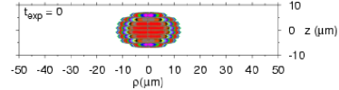
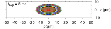
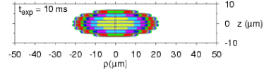
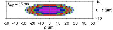
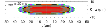
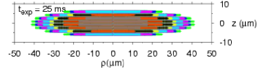
To investigate the expansion of the condensate when the harmonic trap alone is switched off we use optical-lattice strength . Once the condensate is prepared on the joint optical-lattice and harmonic potentials the harmonic potential is switched off and the expansion studied under the influence of the optical trap alone. The view of the condensate at different expansion times , 5 ms, 10 ms, 15 ms, 20 ms and 25 ms are shown in figure 1. The view at ms is similar to figure 1 (b) of [10] after 23 ms. The strong optical lattice divides the condensate into smaller pieces trapped in different lattice sites. With time one piece of BEC in a particular site expand perpendicular to the lattice without ever moving to a neighboring lattice. Consequently, the BEC expands only in the radial direction and maintains a constant size in the axial direction.
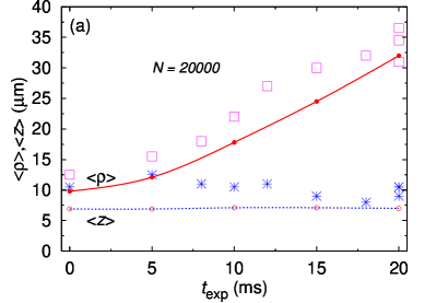
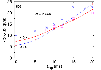
Next we calculate and which are the half-widths of Gaussian fits to the density profile in the lattice (axial) and radial directions, respectively, for different expansion times. The results are plotted in figure 2 (a) for and compared with the experiment of [10]. In figure 2 (b) we plot the same results of expansion as in figure 2 (a) for and compare with the experiment [10]. Considering the 5 m resolution of the imaging system [11] the agreement between the present numerical simulation and experiment is good.
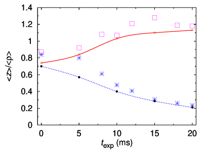
Next we perform the same expansions of figure 2 with optical lattices of strength and 0 and plot the ratio in these cases for different expansion times and compare with the experimental results of [11]. The agreement is good. In both figures 2 and 3 the agreement is better for large expansion times. At large expansion times the size is larger and hence possibly has less experimental error thus leading to a better agreement with experiment.
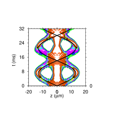
Müller et al. [12] performed a different type of expansion experiment on a BEC formed on a joint optical-lattice and harmonic traps upon switching off only the optical-lattice trap. The condensate pieces from different sites expand, overlap and interfere to form a pattern with three peaks which oscillate according to (6). In figure 4 we show the contour density plot of of (3) as functions of and . This clearly shows the simple harmonic motion of the two side peaks which is compared with the simple theoretical prediction (6). The agreement between the two is good.
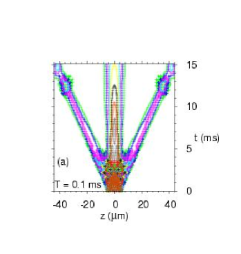
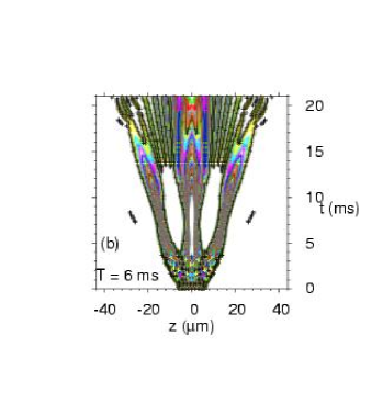
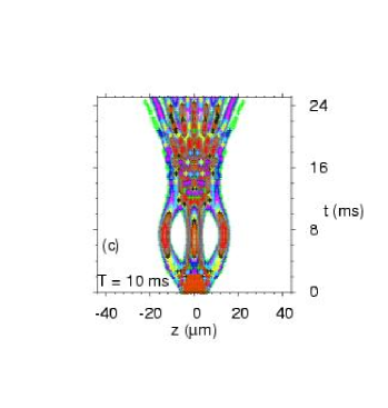
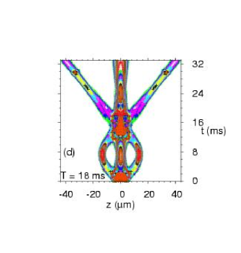
Finally, Müller et al. [12] observed in a remarkable experiment the evolution of the interference patterns (formed upon switching off the optical-lattice trap) in the harmonic trap alone for different times. Then they removed the harmonic trap and observed the free expansion of the BEC. For small hold times in the magnetic trap the interference pattern is clearly visible. They found that with the increase of hold time the prominent interference pattern first becomes blurred and then disappears completely. Then it reappears prominently after a complete half cycle of oscillation according to (6). In this case the period of oscillation is 28.2 ms. The numerical simulation at ms in figure 5 (a) shows the clear trails corresponding to the interference pattern in agreement with [12]. The complete free expansion for a hold time leads to a plot indistinguishable from figure 5 (a). In this case the velocity of the side peaks is m/ms. After 15 ms of free expansion each side peak moves 44.4 m consistent with the simulation of figure 5 (a). In figure 5(b) it is blurred at ms in agreement with [12]. The interference pattern is completely destroyed at ms and again revived after a half cycle of oscillation at ms in figures 5 (c) and (d), respectively, in agreement with experiment.
The explanation for the phenomenon observed in figures 5 is as follows. As the system oscillates in the harmonic potential upon the removal of the optical-lattice potential, after every half cycle of oscillation the system passes through the same initial state when the optical-lattice potential is removed [17]. This initial state is a coherent state on the optical lattice and after a free expansion leads to the interference pattern. However, if the system is allowed to evolve in the harmonic potential for some time after removing the optical-lattice potential and then subject to a free expansion a completely different scenario emerges. In general, the three expanding bright spots would now be moving freely in “wrong” directions so that they may interact and collide with each other upon removal of the harmonic trap and lose their identity resulting in a loss of the observed interference pattern in figures 5. This defocussing effect in the interference pattern would be absent for hold times equal to a multiple of half period of oscillation and would be minimal for hold times near these values consistent with figures 5. There has been a recent attempt to study a similar phenomenon in a different context using a one-dimensional mean-field model [19].
4 Conclusion
In conclusion, using the explicit numerical solution of the axially-symmetric GP equation we have studied the expansion of a BEC formed in a joint harmonic and optical-lattice traps when either trap is removed. When the harmonic trap is removed the piece of condensate in a particular site expands radially without moving to the next site. As a result the whole condensate expands radially maintaining a fixed axial size. The shape of the condensate and its radial and axial sizes during expansion are found to evolve in agreement with the experiments of [10, 11]. When the optical trap is removed the pieces of the BEC at different sites expand and interfere to form a distinct pattern with three peaks which keep on oscillating according to (6) in agreement with present simulation and experiment of [12]. If the interference pattern is allowed to evolve in the harmonic trap for some hold time and the harmonic trap removed, prominent interference pattern appears for small hold time, which become blurred and finally, disappear with the increase of hold time in agreement with the experiment of [12]. Finally, for hold times larger than half period of oscillation the interference pattern reappears as in experiment.
Reference
References
- [1] Anderson B P and Kasevich M A 1998 Science 282 1686
- [2] Orzel C, Tuchman A K, Fenselau M L, Yasuda M and Kasevich M 2001 Science 291 2386
- [3] Greiner M, Mandel O, Esslinger T, Hänsch T W and Bloch I 2002 Nature (London) 415 39 Greiner M, Mandel O, Hänsch T W and Bloch I 2002 Nature (London) 419 51
- [4] Cataliotti F S, Burger S, Fort C, Maddaloni P, Minardi F, Trombettoni A, Smerzi A and Inguscio M 2001 Science 293 843
- [5] Adhikari S K 2003 Eur. Phys. J. D 25 161
- [6] Morsch O, Müller J H, Cristiani M, Ciampini D and Arimondo E 2001 Phys. Rev. Lett. 87 140402
- [7] Cataliotti F S, Fallani L, Ferlaino F, Fort C, Maddaloni P and Inguscio M 2003 New J. Phys.5 71
- [8] Strecker K E, Partridge G B, Truscott A G and Hulet R G 2002 Nature (London) 417 150
- [9] Smerzi A, Trombettoni A, Kevrekidis P G and Bishop A R 2002 Phys. Rev. Lett 89 170402 Adhikari S K 2003 Phys. Lett. A 308 302 Adhikari S K 2003 J. Phys. B: At. Mol. Opt. Phys.36 2725 Adhikari S K 2003 Eur. Phys. J D 25 161
- [10] Morsch O, Cristiani M, Müller J H, Ciampini D and Arimondo E 2002 Phys. Rev. A 66 021601
- [11] Morsch O, Cristiani M, Müller J H, Ciampini D and Arimondo E 2003 Laser Phys. 13 594
- [12] Müller J H, Morsch O, Cristiani M, Ciampini D and Arimondo E 2003 J. Opt. B: Quantum Semiclass. Opt.5 S38
- [13] Dalfovo F, Giorgini S, Pitaevskii L P and Stringari S 1999 Rev. Mod. Phys. 71 463
- [14] Adhikari S K 2002 Phys. Rev.A 65 033616 Dalfovo F and Modugno M 2000 Phys. Rev.A 61 023605 Holland M and Cooper J 1996 Phys. Rev.A 53 R1954 Hosten O, Vignolo P, Minguzzi A, Tanatar B and Tosi M P 2003 J. Phys. B: At. Mol. Opt. Phys.36 2455
- [15] Adhikari S K 2002 Phys. Rev. E 65 016703
- [16] Adhikari S K and Muruganandam P 2002 J. Phys. B: At. Mol. Opt. 35 2831 Muruganandam P and Adhikari S K 2003 J. Phys. B: At. Mol. Opt. Phys.36 2501
- [17] Adhikari S K and Muruganandam P 2003 Phys. Lett. A 310 229
- [18] Xiong H, Liu S, Huang G and Xu Z 2002 J. Phys. B: At. Mol. Opt. Phys.35 4863
- [19] Morsch O, Müller J H, Ciampini D, Cristiani M, Blakie P B, Williams C J, Julienne P S and Arimondo E 2003 Phys. Rev.A 67 031603