Quasi-Langmuir-Blodgett Thin Film Deposition of Carbon Nanotubes
Abstract
The handling and manipulation of carbon nanotubes continues to be a challenge to those interested in the application potential of these promising materials. To this end, we have developed a method to deposit pure nanotube films over large flat areas on substrates of arbitrary composition. The method bears some resemblance to the Langmuir-Blodgett deposition method used to lay down thin organic layers. We show that this redeposition technique causes no major changes in the films’ microstructure and that they retain the electronic properties of as-deposited film laid down on an alumina membrane.
Carbon nanotubes have emerged as materials of fundamental importance and great application potential due to their exceptional electrical, mechanical, and thermal properties [1, 2]. Various proposals exist for their incorporation into devices [3, 4] in single tube or thin film architectures. It has recently been found that networks of nanotubes can act as conducting channels in field effect transistors (FETs) [5, 6]. In addition, such films could be used in fault tolerant chemical or biological sensors [7, 8, 9, 10, 11], thermal heat shunts, as well as in measurements of fundamental nanotube properties in cavity and optical experiments [12]. For such applications the preparation of uniform flat films is of paramount importance.
Although a number of methods do exist it is still far from a trivial task to prepare thin relatively uniform films. The deposition of such films from solution is difficult as nanotubes have very poor solubility in typical solvents without the use of surfactants. Strong intertube attractions, violent hydrophobicity, and low solubility at moderate concentrations all fight against typical wet chemistry techniques in making uniform films. Even if nanotubes can be suspended at a low concentrations under certain conditions [13], simple air drying of well suspended nanotubes on substrates results in flocculation when the local concentration approaches the solubility limit. Surfactants that make the nanotubes compatible with aqueous dispersions may be inappropriate for applications that require pure nanotubes. It is possible to deposit from dilute suspensions onto filtering membranes, but unless other steps are taken then one is constrained to use the filter as a substrate. This may be inappropriate for applications where one wants to apply gate voltages to the film (in FETs) or use optically transparent substrates. Under some situations, nanotubes can be deposited with spin coating, but for thin films (1 m), it is difficult to get adequate uniformity with such a method. A method has been found to create aligned thin films from evaporation of Triton X suspensions at the air-substrate-suspension triple line, but this technique seems to be limited to collodial dispersions and short nanotubes [14].
Very thin nanotube films can be grown using new chemical vapor deposition (CVD) based methods [15, 16]. However, this latter process requires innovative catalyst deposition and high temperatures - not compatible with CMOS technology - for the nanotube growth. These are barriers for a nanotube-CMOS integration process, in particular in the case of substrates that are not heat tolerant.
In this work we describe a method of laying down thin uniform films of carbon nanotubes on substrates of arbitrary composition that has a number of advantages over the above described techniques. A dilute nanotube solution is deposited onto an alumina membrane. The volume below the membrane is then back-filled with a fluid (typically deionized water) immiscible with the suspending liquid; the nanotube film can then be floated on an aqueous layer as a ’raft’. Upon drawing a substrate through the free liquid surface a thin uniform coating of nanotubes can be transferred.
Our method bears some resemblance to the Langmuir-Blodgett thin film deposition used to create uniform layers of organic molecules. In the Langmuir-Blodgett technique a hydrophobic group enables a thin film to lay on a free surface of a subphase compound (typically water). Although true Langmuir-Blodgett thin films have been made with nanotubes embedded in a surfactant matrix suspended on top of an aqueous subphase and then pulling the substrate through the surface [17], such deposition methods are not useful if the final nanotube product need be pure.
This technique has a number of important advantages over simple air drying of a liquid suspension of nanotubes. As detailed above, the liquid phase interaction between nanotubes in solution results in large flocculation effects as a nanotube suspension dries. Air drying gives totally unsuitable results, where nanotubes clump themselves in concentrated 0.1-mm ’piles’. These kind of effects even come into play when spin-coating nanotubes and prevent very thin films from being deposited uniformly.
High pressure carbon monoxide (HiPCO) process single wall nanotubes were obtained from Carbon Nanotechnologies Inc and additionally purified based on a procedure derived from Chiang et al. [18]. Nanotubes, held in an alumina crucible, were allowed to react in moist air (obtained by bubbling ambient air through an immersed frit in room temperature water) at 225 degree Celsius for 18h (using a tubular oven; flow = 0.1 L/min). The remaining solid was suspended in concentrated HCl (37%, ACS grade Aldrich) and immersed in an ultrasound bath for 30 min. The nanotubes were then filtered, rinsed, and washed with water until a neutral pH was reached and then dried in a vacuum oven.
The purified nanotubes were ultrasonically dispersed for 30 minutes in 10:1 ratio of 1,2-dimethylbenzene (ortho-xylene) and 1,2-dichlorobenzene. The nanotube concentration in solution was 3 mg/L. It is a matter of some debate whether a true solution of nanotubes versus a suspension can be obtained. As we don’t make a distinction, we estimate the saturation concentration of nanotubes in our solvent to be approximately 15 mg/L as defined in Ref. [13] which is significantly greater than our working concentration.
A specified amount of solution (for the below images - an amount sufficient to give 8.3g/cm2 which gives an m thick film) is deposited onto an alumina membrane (Whatman 0.02 m pore size). A vacuum can then be engaged which allows one to remove the liquid smoothly and uniformly on a time scale short enough that flocculation and large-scale structures do not have time to form. We henceforth refer to the film formed on the alumina membrane that employs it as a substrate as ’as-deposited’. As-deposited films were also measured for comparison purpose. After the liquid has been removed, pumping continues and the film is allowed to dry for some additional time. Exact numbers are difficult to give; at our vacuum pumping rate, we dried the films for 1 minute after the excess liquid had been removed. This leaves a nanotube network with no excess fluid but which is still somewhat damp with the suspension fluid.
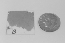
After deposition on the alumina membrane the chamber underneath the film is backfilled with deionized water. Our apparatus is constructed such that this water can be allowed to wash up and over the deposited nanotube film. We have found that the wetting of the alumina membrane and intended deposition substrate is aided by the addition of 2% isopropanol to the deionized water, although under some circumstances this caused the nanotube layer to ’shrivel’. As the fluid washes over the filter, parts of the film, still wet with the suspending fluid, will lift off the substrate and float on top of the water in the form of a single or possibly multiple large ’rafts’. The intended final deposition substrate (glass cover slides in the below images) can be slipped through the free surface and under the floating rafts, whereby the vacuum can be reengaged and the water removed, redepositing the nanotube film directly on top of the new substrate. If the as-deposited film did not immediately lift up, subsequent water washes typically dislodged it. Using the above method, we have succeeded in laying down large scale relatively uniform films with areas of up to 3.3cm2 as seen in Fig. 1.
The nanotube suspending solution must be chosen carefully. We chose to use a hybrid mixture to optimize the necessary features of high nanotube solubility, a specific gravity of less than 1, and immiscibility in water. Two of the best solvents for nanotubes 1,2-dichlorobenzene (solubility up to 95 mg/L) and chloroform ( 30 mg/L) [13] have relatively high specific gravities (1.3 and 1.48 respectively). Such solvents are inappropriate as it is essential to our technique that the solvent have a density less than that of water, otherwise the ’raft’ will not float. A number of other candidate solvents (for instance tetrahydrofuran and dimethylformamide) are miscible in water and hence inappropriate. For this reason we chose to use a 10:1 ratio of 1,2-dimethylbenzene (ortho-xylene) and 1,2-dichlorobenzene. The solution combines the features of reasonably high nanotubes solubility (estimated to be 15mg/L), low specific gravity (0.92g/ml), and immiscibility in water.
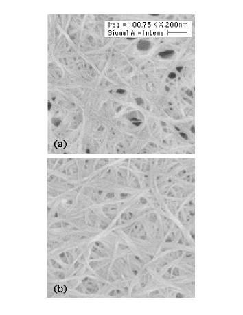
One may have concerns regarding adverse effects the films may suffer during their immersion and redeposition. For instance the extreme hydrophobicity of the nanotubes might cause them to clump into thicker ropes upon exposure to water despite being reasonably well dispersed prior to alumina membrane deposition. That this is not a concern can be seen in Figs. 2a and 2b. Here scanning electron microscope (SEM) micrographs of films, both ones as-deposited and with the water immersion and redeposition steps, show that the films appear to consist of well separated 6 nanotube wide ’ropes’. There is essentially no difference in their microstructure indicating that the film morphology does not suffer any gross effects due to water immersion.
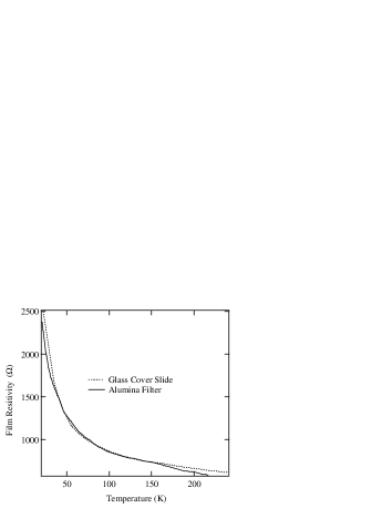
Temperature dependent DC resistivity measurements support the inference that there are no subtle structural changes which may influence the film’s transport properties. Data were taken on a number of nanotube films, both as-deposited and also ones immersed in water and then redeposited on glass slides as described above. The measurements were done the standard 4-probe technique with currents of 1 A under 1 atm. of helium gas. Electrical contact was made via Epotek silver epoxy. In Fig. 3, is shown the resistivities of two representative films. The displayed data have been corrected for geometrical factors and this is given in ohms per square unit. Both the overall magnitude of the resistivity and its temperature dependence are unaffected by the redeposition process. The very small differences observed are within the typical variability of as-deposited films.
In conclusion we have described a method to deposit thin films of carbon nanotubes on substrates of arbitrary composition. We have shown that the structural and electronic properties of the films are essentially unaffected by this redeposition method, opening the way for the incorporation of such films into nanoscale electronic devices. While CVD growth of carbon nanotubes will most probably remain the method of choice for nanotube-silicon integration, the method described above may have promise in fabricating thin films on surfaces that cannot withstand the CVD growth environment. As such, Quasi-Langmuir-Blodgett thin film deposition may become an effective way for integration of networks into transparent or plastic substrates, which would essential for flexible electronics and display applications.
The authors would like to thank N.S. Armitage and R. Crane for various insightful conversations and S. Kwan for help in the SWNT purification.
REFERENCES
- [1] M. Dresselhaus, G. Dresselhaus, P. Eklund, R. Saito, Physics World 11, (1): 33-38 (1998).
- [2] C. Dekker C, Physics Today 52 (5): 22-28 (1999).
- [3] A. Bachtold, P. Hadley, T. Nakanishi, C. Dekker, Science 294, 1317-1320 (2001).
- [4] R. Martel, T. Schmidt, H.R. Shea, T. Hertel, P. Avouris, Appl. Phys. Lett. 73, 2447 (1998).
- [5] J.-C.P. Gabriel et al., Mat. Res. Soc. Symp. Proc. 762, Q.12.17.1-7 (2003).
- [6] E.S. Snow, J.P. Novak, P.M. Campbell, D. Park., App. Phys. Lett. 82, 2145 (2003).
- [7] P.G. Collins, K. Bradley, M. Ishigami, A. Zettl, Science 287, 1801 (2000).
- [8] J. Kong, N.R. Franklin, C. Zhou, M.G. Chapline, S. Peng, K. Cho, H. Dai, Science 287, 622 (2000).
- [9] R.J. Chen, Y. Zhang, D. Wang, H.J. Dai, Am. Chem Soc. 123, 3838-3839 (2001).
- [10] M. Shim, N.W.S. Kam, R.J. Chen, Y. Li, H. Dai, Nano Lett. 2, 285-288 (2002).
- [11] A Modi et al., Nature 424, 171 (2003).
- [12] N.P. Armitage, P. Tran, and George Grüner, manuscript in preparation.
- [13] Jeffrey L. Bahr et al. Chem. Commun. 2, 193-194 (2001).
- [14] H. Shimoda, L. Fleming, K. Horton, and O. Zhou, Physica-B Condensed Matter. 323, 135 (2002).
- [15] Z. Zhang, B.Q. Wei, G. Ramanath, P.M. Ajayan, Appl. Phys. Lett. 77, 3764-3766 (2000).
- [16] B.Q. Wei et al., Nature 416, 495-496 (2002).
- [17] V. Krstic, et al. Chem. Mater. 10, 2338 (1998).
- [18] Chiang et al. J. Phys. Chem. B 105 (35) 8297 (2001).