Differential Photoelectron Holography:
A New Approach for Three-Dimensional Atomic Imaging
Abstract
We propose differential holography as a method to overcome the long-standing forward-scattering problem in photoelectron holography and related techniques for the three-dimensional imaging of atoms. Atomic images reconstructed from experimental and theoretical Cu 3p holograms from Cu(001) demonstrate that this method suppresses strong forward-scattering effects so as to yield more accurate three-dimensional images of side- and back-scattering atoms.
pacs:
61.14.-x, 42.40.-iHolography Gabor:1948 is a method of recording both the amplitudes and phases of waves scattered by an object illuminated with coherent radiation, and using this information to directly construct a three-dimensional image of the object. Szöke Szoke:1986 first suggested that coherent outgoing waves from atomically-localized sources of photoelectrons, fluorescent x-rays, and -rays could be used to achieve atomic-scale holography. This idea was initially demonstrated theoretically for the case of photoelectrons by Barton Barton:1988 , and then extended into a multi-energy format by Barton and Terminello and by Tong and co-workers Barton:1991 . By now several experimental approaches to such atomic-resolution holography have been demonstrated, including photoelectrons Tonner:1991 ; Terminello:1993 ; Tong:1995 ; Len:1999 , Auger electrons Saldin:1993 , Kikuchi electrons Wei:1994 , diffuse-scattered low-energy electrons Saldin:1998 , fluorescent x-rays in either a direct mode Tegze:1994 or a multi-energy inverse mode Gog:1996 , -rays Korecki:1997 , and bremsstrahlung x-rays Bompadre:1999 .
Among these methods, photoelectron holography (PH) has the advantages of being capable of studying the local atomic structure around each type of emitter without requiring long-range order and of distinguishing emitters through core-level binding-energy shifts Len:1999 . Photoelectron holograms also show strong modulations of up to 50%, so such effects are easily measurable. However, PH can suffer from serious image aberrations due to the strength of electron scattering. The atomic scattering factor is a highly anisotropic function of scattering angle, and can depend strongly on electron kinetic energy . In particular, as increases above a few hundred eV, becomes more and more significant in the forward direction, resulting in a strong forward-scattering (FS) peak Fadley:1993 that can induce image aberrations. Beyond this, PH also can suffer from multiple-scattering (MS) effects due to the scattering strength.
Various reconstruction algorithms and measurement methods Barton:1991 ; Tonner:1991 ; Tong:1995 ; Greber:1996 have been proposed to correct for the anisotropic and MS effects, some of which can be summarized via
| (1) |
where is the image intensity at position r, is the normalized 3D hologram, and the function or operator permits describing the difference between algorithms, with =1 in the original multi-energy formulations Barton:1991 . One alternative algorithm Tonner:1991 sets so as to divide out the anisotropic , where is the angle between r and k. In another algorithm Tong:1995 based on the more ideal electron back scattering (BS), a window function for that limits the integral in Eq. (1) to be in a small cone of around is chosen to emphasize the imaging of BS atoms. Although successful in several applications Tong:1995 ; Luh:1998 , it is difficult to apply this small-cone method to many systems where the imaging of FS or even side-scattering (SS) atoms is important, such as epitaxial films and buried interfaces. In fact, imaging of “bulk” atoms surrounded by FS and BS atoms via PH has proven to be especially difficult [cf. Figs. 7-9 in ref. Len:1999 ], with most successful applications being to emitters in the first few layers near a surface.
To overcome such FS effects, we propose in this Letter “differential holography”. By simply replacing in Eq. (1) by its -derivative (i.e. or more conveniently by a numerical difference between two ’s at different energies (, FS effects can be greatly suppressed. We have applied this method to multi-energy holograms for Cu 3p emission from Cu(001), and show that this provides images that are improved over prior work in several respects.
To avoid confusion with other methods in PH, we also note that “derivative” PH has been proposed and used successfully by Chiang and co-workers Luh:1998 . However, the purpose here is to eliminate uncertainties in due to the variation of experimental conditions by first taking logarithmic derivatives that are then reintegrated into “self-normalized” intensities; thus, it is still finally that is used in Eq.(1).
The principle of differential photoelectron holography (DPH) is as follows. We consider the single-scattering expression of for an emitter-scatterer pair spaced by a vector Fadley:1993 :
| (2) |
where is the intensity that would be observed without atomic scattering, and is the scattering phase. If is sufficiently small so that , where is the change in , the difference of two holograms at can be written in a similar form to Eq. (Differential Photoelectron Holography: A New Approach for Three-Dimensional Atomic Imaging) as:
| (3) |
where direction is defined by angles and , the “effective” scattering amplitude is defined as , and is the average of ’s at . In the FS region where , is thus very small, approaching zero in the limit of . If k is also small, is proportional to ; thus, DPH not only suppresses the FS effects, but also enhances the imaging of distant atoms. In Fig. 1, and are plotted as a function of for Cu-Cu nearest neighbors (=2.56 Å). For =4.6 Å-1 and k=0.2 Å-1, is significant only in the region of . Therefore, the imaging of SS and BS atoms is expected, while it will be difficult for this case to image FS atoms. On the other hand, for =8.8 Å-1 and a larger fractional k=1.0 Å-1, is significant not only in the BS region but also in the range of 30o-90o. Since near-neighbor FS diffraction fringes extend out beyond 30o Fadley:1993 ; Omori:1999 , we might expect the latter choice to also permit imaging FS atoms. In this way, the relative sensitivity of DPH to SS and FS atoms can be “tuned” by selecting the range and step width of scans. Finally, we note that the suppression of MS effects by means of a transform over a volume in k space is well known in normal multi-energy PH Barton:1991 and this suppression will be equally present in DPH. If anything, the inherent elimination of strong FS effects in DPH should lead to even better MS suppression.
To demonstrate DPH experimentally, photoelectron holograms from Cu(001) were measured at beamline 7.0 of the Advanced Light Source at the Lawrence Berkeley National Laboratory. Photoelectron spectra for Cu 3p emission were collected at 25 energies over =4.5-9.3 Å-1 (=77-330 eV) with a constant step of k=0.2 Å-1 (Ek =7-14 eV), along 65 different directions over a symmetry-reduced 1/8 of the total solid angle above the specimen, and with a polar angle range from =0o (surface normal) to 70o. The photoelectron intensity ,,) was fitted by low-order polynomials to obtain the smooth background intensity Len:1999 ; Len:1997 :
| (4) |
Three kinds of were obtained from this fitting: by fitting the second factor of Eq. (4) to a scanned-angle pattern at each fixed Terminello:1993 , by fitting the first factor to a scanned-energy curve at each fixed direction Tong:1995 and by fitting both factors to the full data set of at one time, with the last expected to be the most accurate from an a priori point of view Len:1999 . The -differences from were also used for DPH in what we will term Method D (i.e., . Since low-frequency fringes due to FS events in are automatically removed in Method B Wei:1994 , the resulting inherently deviates from the true defined as the intensity without scattering, especially in the FS direction. In addition, since and are independently normalized without considering the continuity of in the whole sampled space in Methods A and B, they could degrade holographic fringes in and , respectively. By contrast, Method C takes into account the continuity of over the whole data set, but the FS peaks remain in ; however, they should be eliminated in . The original transform of Eq. (1) was used for all four data sets; but to avoid the abrupt truncation of the integral in Eq. (1), was taken to be the product of a Gaussian function of and a Hanning function , with an additional multiplication by to make atoms at larger distances more visible.
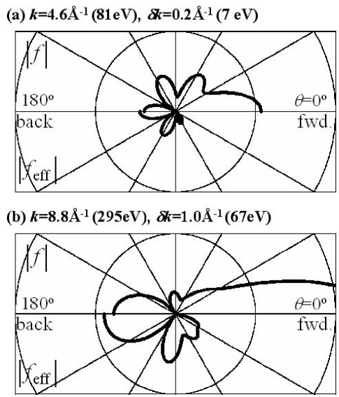
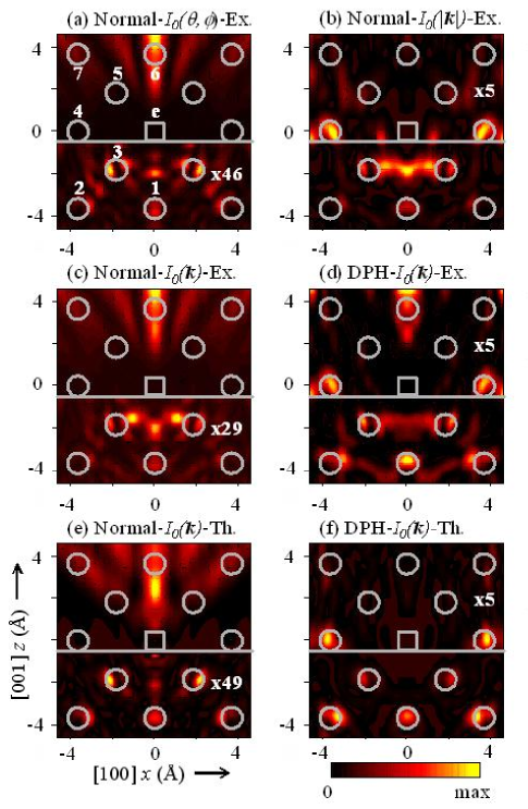
Figure 2 shows atomic images reconstructed from A-D in the vertical (100) plane of Cu(001). In Methods A and C, only elongated features related to FS effects from atoms of types 6 and 7 are observed above Å (the arbitrary location of a change in image multiplication). This is consistent with a previous PH study of W(110) Len:1999 , in which Method C was used. By contrast, it has been reported Terminello:1993 that FS atoms of type 5 have been imaged via Method A from Cu 3p holograms for Cu(001) obtained at 9 energies. Even if possible differences in the two sets of experimental data are taken into account, it is difficult to conclude from our results that the images of these FS atoms can be resolved from strong artifacts via Method A. Below , several peaks near the BS positions 1-3 are observable for A and C among various strong artifacts, but only with the help of higher image amplifications of 46 and 29, respectively.
In Methods B and D, image intensities are stronger in the BS region, with the relative image amplification factors being reversed in sense and smaller at compared to A and C. In Method D, a strong, somewhat elongated peak is observed at the FS position 6, with weaker features that appear to be associated with atoms 7 also present in the corners of the image. In both B and D, two strong peaks are observed at the SS positions 4 above and five peaks are observed at the BS positions 1-3 below . However, the most intense features in Method B are the artifacts between the two nearest BS atoms of type 3. In Method D, by contrast, the five strongest peaks below are of roughly equal intensity and correspond reasonably well to the near-neighbor BS atoms. Therefore, we find Method D to be the most robust for imaging both SS and BS atoms (as well as to some degree also FS atoms 6), even if there are shifts in position of approximately 0.1 Å for type 1, 0.6 Å for 2, and 0.3 Å for 3. Such peak shifts relative to the true atomic positions, as observed in all methods, can be attributed to the present neglect of corrections for both the scattering phase and the inner potential.
For comparison with experiment, we have also performed MS simulations of , using a cluster method fully described elsewhere Chen:1998 . The theoretical was obtained simply as the square of the zeroth-order wave function without scattering. Images reconstructed from the theoretical and via Methods C and D are shown in Figs. 2(e) and (f) and can be compared with Figs. 2(c) and (d), respectively. The main features in Figs. 2(c) and (d) are well reproduced by our simulations, although the artifacts between the atoms 3 are much stronger in experiment for C, and the relative intensity in the region of FS atom 6 is stronger in experiment for D. Even though the ideal was used for image reconstruction, no atomically-resolved SS or FS peaks are observable in Fig. 2(e). Therefore, the corresponding artifacts in Fig. 2(c) are not purely due to the uncertainties in the experimental data and any errors in the subtraction, but must have their origin in the MS effects and basic imaging algorithm. On the other hand, Fig. 2(f) exhibits well-resolved peaks at the SS and BS positions. Since there are no artifacts below in Fig. 2(f), the artifacts in Fig. 2(d) are by contrast considered to be purely due to the experimental noise and other non-idealities in the data analysis.
We have also generated full three-dimensional atomic images from the experimental data via , although length limitations prevent showing these here. In these images, we find in addition to the atoms 1-4 and 6 in Fig. 2, two other types of near-neighbor BS and SS atoms located in the vertical (110) plane (denoted types 2’ and 4’ and situated in the same horizontal layers as 2 and 4, respectively). All of these atoms are reasonably well reconstructed, with only a few, such as 2, being significantly shifted in position, but most within a few tenths of an Å of the correct positions in all directions. The overall positional errors for all of the atoms compared to the known Cu lattice can be summarized as (radial location shift in /(vertical location shift in , and are: 0.0 Å/0.1 Å for atoms 1, 0.6 Å/0.1 Å for 2, 0.3 Å/0.1 Å for 2’, 0.2 Å/0.1 Å for 3, 0.1 Å/0.0 Å for 4, 0.3 Å/0.0 Å for 4’, and 0.0 Å/0.4 Å for 6. As a further indication of the overall image quality obtained by DPH, the reader is referred to an animated comparison of 3D images for the four approaches of Figs. 2(a)-(d), in which DPH is alone in imaging approximately 15 near-neighbor atoms Animated:1 .
Finally, we compare DPH with a very recently introduced approach for PH termed near-node holography Wider:2001 , in which FS effects are suppressed by using a special experimental geometry with electron exit nearly perpendicular to light polarization. Although this technique is promising, DPH has the advantages that it does not require a special experimental geometry or s-subshell-like form for the photoelectric cross section, that it seems to yield images of as good or better quality Animated:1 ; Wider:2001 and that it can be used in other types of holography in which polarization cannot be varied.
In summary, we have demonstrated differential photoelectron holography (DPH) as a powerful method for overcoming the FS problem in PH and enhancing image quality for any kind of system in which FS can arise, as for example, bulk emission and buried interfaces. This method should also be helpful in other types of electron holography in which energy can be stepped in a controlled way (e.g. Kikuchi Wei:1994 or LEED Saldin:1998 holography). The reconstructed images for Cu 3p/Cu(001) demonstrate that DPH is successful in suppressing the FS effects so as to image SS, BS, and to some degree also FS, atoms with accuracies of 0.1-0.6 Å.
This work was supported in part by the Director, Office of Energy Research, Basic Energy Science, Materials Sciences Division of the U. S. Department of Energy under Contract No. DE-AC03-76SF00098. S.O. and Y.N. also acknowledge the support of the Japan Society for the Promotion of Science (Grant No. JSPS-RFTF 98R14101).
References
- (1) D. Gabor, Nature 161, 777 (1948).
- (2) A. Szöke, in Short Wavelength Coherent Radiation: Generation and Applications, AIP Conf. Proc. No. 147, edited by D. T. Attwood and J. Boker (AIP, New York, 1986), p. 361.
- (3) J. J. Barton, Phys. Rev. Lett. 61, 1356 (1988).
- (4) J. J. Barton, Phys. Rev. Lett. 67, 3106 (1991); J. J. Barton and L. J. Terminello, in Structure of Surfaces III, edited by S. Y. Tong, M. A. Van Hove, X. Xide and K. Takayanagi (Springer-Verlag, Berlin, 1991), p. 107; S. Y. Tong, H. Li and H. Huang, Phys. Rev. Lett. 67, 3102 (1991).
- (5) B. P. Tonner et al., Phys. Rev. B 43, 14423 (1991).
- (6) L. J. Terminello, J. J. Barton and D. A. Lapiano-Smith, Phys. Rev. Lett. 70, 599 (1993).
- (7) S. Y. Tong, H. Li and H. Huang, Phys. Rev. B 51, 1850 (1995); H. Wu and G. J. Lapeyre, ibid. 51, 14549 (1995).
- (8) P. M. Len et al., Phys. Rev. B 59, 5857 (1999).
- (9) D. K. Saldin, G. R. Harp and X. Chen, Phys. Rev. B 48, 8234 (1993).
- (10) C. M. Wei, I. H. Hong and Y. C. Chou, Surf. Rev. Lett. 1, 335 (1994).
- (11) D. K. Saldin and P. L. DeAndres, Phys. Rev. Lett. 64, 1270 (1990); K. Reuter et al., Phys. Rev. B 58, 4102 (1998).
- (12) M. Tegze and G. Faigel, Europhys. Lett. 16, 41 (1991); P. M. Len et al., Phys. Rev. B 50, 11275 (1994).
- (13) T. Gog et al., Phys. Rev. Lett. 76, 3132 (1996).
- (14) P. Korecki, J. Korecki and T. lezak, Phys. Rev. Lett. 79, 3518 (1997).
- (15) S. G. Bompadre, T. W. Petersen and L. B. Sorensen, Phys. Rev. Lett. 83, 2741 (1999).
- (16) C. S. Fadley, Surf. Sci. Rep. 19, 231 (1993).
- (17) T. Greber and J. Osterwalder, Chem. Phys. Lett. 256, 653 (1996).
- (18) D. –A. Luh, T. Miller and T. –C. Chiang, Phys. Rev. Lett. 81, 4160 (1998).
- (19) S. Omori, T. Kozakai and Y. Nihei, Surf. Rev. Lett. 6, 1085 (1999).
- (20) P. M. Len, Ph.D. thesis, University of California, Davis (1997).
- (21) Y. Chen et al., Phys. Rev. B 58, 13121 (1998); multiple scattering photoelectron diffraction program athttp://electron.lbl.gov/mscdpack/mscdpack.html.
- (22) Animated images in 3D showing the four experimental cases of Figs. 2(a)-2(d) also appear at http://electron.lbl.gov/marchesini/dph/ and http://ftp.aip.org/epaps/phys_rev_lett/[epaps_code]
- (23) J. Wider et al., Phys. Rev. Lett. 86, 2337 (2001).