URL: ]http://cua.mit.edu/ketterle_group/
Atom interferometry with Bose-Einstein condensates in a double-well potential
Abstract
A trapped-atom interferometer was demonstrated using gaseous Bose-Einstein condensates coherently split by deforming an optical single-well potential into a double-well potential. The relative phase between the two condensates was determined from the spatial phase of the matter wave interference pattern formed upon releasing the condensates from the separated potential wells. Coherent phase evolution was observed for condensates held separated by 13 m for up to 5 ms and was controlled by applying ac Stark shift potentials to either of the two separated condensates.
pacs:
03.75.Dg, 39.20.+q, 03.75.-b, 03.75.LmDemonstrating atom interferometry with particles confined by magnetic Ott et al. (2001); Hänsel et al. (2001a); Leanhardt et al. (2002); Schneider et al. (2003) and optical Dumke et al. (2002) microtraps and waveguides would realize the matter wave analog of optical interferometry using fiber-optic devices. Current proposals for confined-atom interferometers rely on the merger and separation of two potential wells to coherently divide atomic wavepackets Hinds et al. (2001); Hänsel et al. (2001b); Andersson et al. (2002). This type of division differs from previously demonstrated atomic beam splitters. To date, atomic beams and vapors have been coherently diffracted into different momentum states by mechanical Carnal and Mlynek (1991); Keith et al. (1991) and optical Kasevich and Chu (1991) gratings, and Bose-Einstein condensates have been coherently delocalized over multiple sites in optical lattices Anderson and Kasevich (1998); Orzel et al. (2001); Cataliotti et al. (2001); Greiner et al. (2001, 2002); Mandel et al. (2003). Atom interferometers utilizing these beam splitting elements have been used to sense accelerations Peters et al. (1997); Anderson and Kasevich (1998) and rotations Lenef et al. (1997); Gustavson et al. (1997), monitor quantum decoherence Chapman et al. (1995), characterize atomic and molecular properties Ekstrom et al. (1995), and measure fundamental constants Peters et al. (1997); Gupta et al. (2002).
In this Letter, we demonstrate a trapped-atom interferometer with gaseous Bose-Einstein condensates confined in an optical double-well potential. Condensates were coherently split by deforming an initially single-well potential into two wells separated by 13 m. The relative phase between the two condensates was determined from the spatial phase of the matter wave interference pattern formed upon releasing the atoms from the separated potential wells Andrews et al. (1997); Mandel et al. (2003). This recombination method avoids deleterious mean field effects Smerzi et al. (1997); Stickney and Zozulya (2002) and detects applied phase shifts on a single realization of the experiment, unlike in-trap recombination schemes Hinds et al. (2001); Hänsel et al. (2001b); Andersson et al. (2002).
The large separation between the split potential wells allowed the phase of each condensate to evolve independently and either condensate to be addressed individually. An ac Stark phase shift was applied to either condensate by temporarily turning off the optical fields generating its potential well. The spatial phase of the resulting matter wave interference pattern shifted linearly with the applied phase shift and was independent of the time of its application. This verified the phase sensitivity of the interferometer and the independent phase evolution of the separated condensates. The measured coherence time of the separated condensates was 5 ms.
The present work demonstrates a trapped-atom interferometer with two interfering paths. This geometry has the flexibility to measure either highly localized potentials or uniform potential gradients, such as those arising from atom-surface interactions or the earth’s gravitational field, respectively. In contrast, multiple-path interferometers demonstrated in optical lattice systems are restricted to measurements of the latter Anderson and Kasevich (1998); Mandel et al. (2003).
Bose-Einstein condensates containing over 23Na atoms were created in the state in a magnetic trap, captured in the focus of a 1064 nm optical tweezers laser beam, and transferred into an auxiliary “science” chamber as described in Ref. Gustavson et al. (2002). In the science chamber, the condensate was loaded from the optical tweezers into the interferometer’s single-well optical trap formed by a counter-propagating, orthogonally-polarized 1064 nm laser beam shifted in frequency from the tweezers by MHz to avoid interference effects.
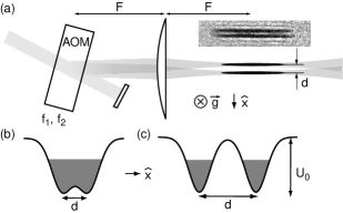
A schematic diagram of the setup for the interferometer’s optical trap is shown in Fig. 1(a). The optical potentials were derived from a collimated laser beam that passed through an acousto-optic modulator (AOM) and was focused onto the condensate with a lens. The AOM was driven by two radio frequency (rf) signals to create the double-well potential. The separation between the potential wells was controlled by the frequency difference between the rf drives. The radius of each focused beam was 5 m. For typical optical powers, this resulted in a single beam trap depth kHz, where is Planck’s constant, and a radial (axial) trap frequency Hz ( Hz).
The condensate was initially loaded into the single-well trap shown in Fig. 1(b). After holding the cloud in this trap for 15 s to damp excitations, the peak atomic mean field energy was kHz. The single-well trap was deformed into the double-well potential shown in Fig. 1(c) by linearly increasing the frequency difference between the rf signals driving the AOM in 5 ms. The amplitude of the rf signals were tailored during the splitting process to guarantee an even division of the condensate atoms and nearly equal trap depths after splitting.
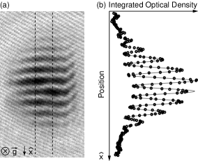
The key achievement of this work was the reproducibility of the spatial phase of the matter wave interference pattern on each realization of the experiment. Figure 2 shows a typical matter wave interference pattern formed by the condensates released from the double-well potential. The reproducibility directly confirmed that deforming the optical potential from a single-well into a double-well coherently split the condensate into two clouds with deterministic relative phase. While past work suffered from an unstable potential barrier separating the two condensates and irreproducible turn off a high current magnetic trap to initiate ballistic expansion Andrews et al. (1997), the current experiment derived its double-well potential from a single laser beam. Thus, vibrations and fluctuations of the laser beam were common-mode to both wells and a clean and rapid trap turn off was achieved.
The condensates were sufficiently separated that their phases evolved independent of each other to the extent that no coupling between the potential wells could be detected. This claim is supported qualitatively by the absorption image in Fig. 1(a) and the observation of high-contrast matter wave interference patterns that penetrated the full atomic density profile with uniform spatial period and no thick central fringe Röhrl et al. (1997), and quantitatively by measurements of the phase evolution (Figs. 3 and 4).
The relative phase between the two separated condensates was determined by the spatial phase of their matter wave interference pattern. For a ballistic expansion time , each condensate had a quadratic phase profile Dalfovo et al. (1999), , where denotes one well or the other, is the condensate density, , is the atomic mass, and is the condensate phase. This resulted in a total density profile for the matter wave interference pattern
| (1) |
where is the relative phase between the two condensates and . To extract , the integrated cross section shown in Fig. 2(b) was fit with a sinusoidally-modulated Gaussian curve, , where is the phase of the interference pattern with respect to a chosen fixed . Ideally, if was set at the center of the two wells, then . However, misalignment of the imaging axis with the direction of gravitational acceleration created a constant offset, . With ms the measured fringe period, m, was within of the point source formula prediction [Eq. (1)], m.
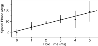
The coherent phase evolution of the split condensates is displayed quantitatively in Figs. 3 and 4. The relative phase, , between the separated condensates was observed to evolve linearly in time and the standard deviation of eight measurements of was degrees up to 5 ms after splitting (Fig. 3). Furthermore, for hold times between 0 and 1 ms, the standard deviation was substantially smaller, degrees. Since distributed randomly between and degrees would have a standard deviation of degrees, the results in Figs. 3 and 4 clearly demonstrate that the separated condensates had a reproducible relative phase after splitting. The linear time evolution of was due to a chemical potential difference between separated condensates and could be controlled by varying the trap depths of the individual potential wells after splitting.
Fundamental limits on the phase coherence between isolated condensates arise due to Poissonian number fluctuations associated with the coherent state description of the condensate Lewenstein and You (1996); Javanainen and Wilkens (1997); Menotti et al. (2001). For our experimental parameters, the time scale for phase diffusion was ms. The uncertainty in determining at longer hold times ms is attributed to axial and breathing-mode excitations created during the splitting process. These excitations lead to interference fringes that were angled and had substantial curvature, rendering a determination of impossible. Splitting the condensate more slowly in an effort to minimize excitations, but still fast compared to the phase diffusion time, did not improve the measured stability of . Since controlling axial excitations appears critical for maintaining phase coherence, splitting condensates that are freely propagating in a waveguide potential may be more promising Leanhardt et al. (2002).
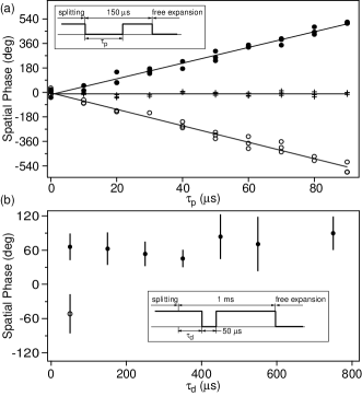
The phase sensitivity of the trapped-atom interferometer was demonstrated by applying ac Stark phase shifts to either (or both) of the two separated condensates. Phase shifts were applied to individual condensates by pulsing off the optical power generating the corresponding potential well for a duration . Figure 4(a) shows that the spatial phase of the matter wave interference pattern shifted linearly with the pulse duration, as expected. Due to the inhomogeneous optical potential, , the applied ac Stark phase shifts varied across the condensate as . Averaging this phase shift over the inhomogeneous condensate density, , approximates the expected spatial phase shift of the matter wave interference pattern as , where is the number of atoms, and and are the trap depth and mean field energy at the center of each potential well, respectively. The measured phase shifts yielded kHz [Fig. 4(b)], which was consistent with calculations based on other measured trap parameters.
The measured phase shifts of the matter wave interference depended only on the time-integral of the applied ac Stark phase shifts [Fig. 4(b)], as expected for uncoupled condensates. The final relative phase, , should be the same on different phase trajectories because the history of phase accumulation does not affect the total amount of accumulated phase. For coupled condensates, Josephson oscillations between the wells would cause the relative phase to vary nonlinearly with time Smerzi et al. (1997); Dalfovo et al. (1999) and produce a time dependent signal in Fig. 4(b). Due to the large well separation and mean field energy kHz below the barrier height, the single-particle tunnelling rate in our system was extremely low ( Hz) Dalfovo et al. (1999), and the condensates were effectively uncoupled.
In conclusion, we have performed atom interferometry with Bose-Einstein condensates confined in an optical double-well potential. A coherent condensate beam splitter was demonstrated by deforming a single-well potential into a double-well potential. The large spatial separation between the potential wells guaranteed that each condensate evolved independently and allowed for addressing each condensate individually. Recombination was performed by releasing the atoms from the double-well potential and allowing them to overlap while expanding ballistically. Implementing a similar readout scheme with magnetic potentials generated by microfabricated current carrying wires should be possible and would eliminate deleterious mean field effects inherent in proposals using in-trap wavepacket recombination. Propagating the separated condensates along a waveguide prior to phase readout would create an atom interferometer with an enclosed area, and hence with rotation sensitivity.
We thank W. Jhe, C. V. Nielsen, and A. Schirotzek for experimental assistance and S. Gupta, Z. Hadzibabic, and M. W. Zwierlein for critical comments on the manuscript. This work was funded by ARO, NSF, ONR, and NASA. M.S. acknowledges additional support from the Swiss National Science Foundation.
References
- Ott et al. (2001) H. Ott, J. Fortagh, G. Schlotterbeck, A. Grossmann, and C. Zimmermann, Phys. Rev. Lett. 87, 230401 (2001).
- Hänsel et al. (2001a) W. Hänsel, P. Hommelhoff, T. W. Hänsch, and J. Reichel, Nature 413, 498 (2001a).
- Leanhardt et al. (2002) A. E. Leanhardt, A. P. Chikkatur, D. Kielpinski, Y. Shin, T. L. Gustavson, W. Ketterle, and D. E. Pritchard, Phys. Rev. Lett. 89, 040401 (2002).
- Schneider et al. (2003) S. Schneider, A. Kasper, C. vom Hagen, M. Bartenstein, B. Engeser, T. Schumm, I. Bar-Joseph, R. Folman, L. Feenstra, and J. Schmiedmayer, Phys. Rev. A 67, 023612 (2003).
- Dumke et al. (2002) R. Dumke, T. Müther, M. Volk, W. Ertmer, and G. Birkl, Phys. Rev. Lett. 89, 220402 (2002).
- Hinds et al. (2001) E. A. Hinds, C. J. Vale, and M. G. Boshier, Phys. Rev. Lett. 86, 1462 (2001).
- Hänsel et al. (2001b) W. Hänsel, J. Reichel, P. Hommelhoff, and T. W. Hänsch, Phys. Rev. A 64, 063607 (2001b).
- Andersson et al. (2002) E. Andersson, T. Calarco, R. Folman, M. Andersson, B. Hessmo, and J. Schmiedmayer, Phys. Rev. Lett. 88, 100401 (2002).
- Carnal and Mlynek (1991) O. Carnal and J. Mlynek, Phys. Rev. Lett. 66, 2689 (1991).
- Keith et al. (1991) D. W. Keith, C. R. Ekstrom, Q. A. Turchette, and D. E. Pritchard, Phys. Rev. Lett. 66, 2693 (1991).
- Kasevich and Chu (1991) M. Kasevich and S. Chu, Phys. Rev. Lett. 67, 181 (1991).
- Anderson and Kasevich (1998) B. P. Anderson and M. A. Kasevich, Science 282, 1686 (1998).
- Orzel et al. (2001) C. Orzel, A. K. Tuchman, M. L. Fenselau, M. Yasuda, and M. A. Kasevich, Science 291, 2386 (2001).
- Cataliotti et al. (2001) F. S. Cataliotti, S. Burger, C. Fort, P. Maddaloni, F. Minardi, A. Trombettoni, A. Smerzi, and M. Inguscio, Science 293, 843 (2001).
- Greiner et al. (2001) M. Greiner, I. Bloch, O. Mandel, T. W. Hänsch, and T. Esslinger, Phys. Rev. Lett. 87, 160405 (2001).
- Greiner et al. (2002) M. Greiner, O. Mandel, T. Esslinger, T. W. Hänsch, and I. Bloch, Nature 415, 39 (2002).
- Mandel et al. (2003) O. Mandel, M. Greiner, A. Widera, T. Rom, T. W. Hänsch, and I. Bloch, Phys. Rev. Lett. 91, 010407 (2003).
- Peters et al. (1997) A. Peters, K. Y. Chung, B. Young, J. Hensley, and S. Chu, Phil. Trans. R. Soc. Lond. A 355, 2223 (1997).
- Lenef et al. (1997) A. Lenef, T. D. Hammond, E. T. Smith, M. S. Chapman, R. A. Rubenstein, and D. E. Pritchard, Phys. Rev. Lett. 78, 760 (1997).
- Gustavson et al. (1997) T. L. Gustavson, P. Bouyer, and M. A. Kasevich, Phys. Rev. Lett. 78, 2046 (1997).
- Chapman et al. (1995) M. S. Chapman, T. D. Hammond, A. Lenef, J. Schmiedmayer, R. A. Rubenstein, E. Smith, and D. E. Pritchard, Phys. Rev. Lett. 75, 3783 (1995).
- Ekstrom et al. (1995) C. R. Ekstrom, J. Schmiedmayer, M. S. Chapman, T. D. Hammond, and D. E. Pritchard, Phys. Rev. A 51, 3883 (1995).
- Gupta et al. (2002) S. Gupta, K. Dieckmann, Z. Hadzibabic, and D. E. Pritchard, Phys. Rev. Lett. 89, 140401 (2002).
- Andrews et al. (1997) M. R. Andrews, C. G. Townsend, H.-J. Miesner, D. S. Durfee, D. M. Kurn, and W. Ketterle, Science 275, 637 (1997).
- Smerzi et al. (1997) A. Smerzi, S. Fantoni, S. Giovanazzi, and S. R. Shenoy, Phys. Rev. Lett. 79, 4950 (1997).
- Stickney and Zozulya (2002) J. A. Stickney and A. A. Zozulya, Phys. Rev. A 66, 053601 (2002).
- Gustavson et al. (2002) T. L. Gustavson, A. P. Chikkatur, A. E. Leanhardt, A. Görlitz, S. Gupta, D. E. Pritchard, and W. Ketterle, Phys. Rev. Lett. 88, 020401 (2002).
- Röhrl et al. (1997) A. Röhrl, M. Naraschewski, A. Schenzle, and H. Wallis, Phys. Rev. Lett. 78, 4143 (1997).
- Dalfovo et al. (1999) F. Dalfovo, S. Giorgini, L. P. Pitaevskii, and S. Stringari, Rev. Mod. Phys. 71, 463 (1999).
- Lewenstein and You (1996) M. Lewenstein and L. You, Phys. Rev. Lett. 77, 3489 (1996).
- Javanainen and Wilkens (1997) J. Javanainen and M. Wilkens, Phys. Rev. Lett. 78, 4675 (1997).
- Menotti et al. (2001) C. Menotti, J. R. Anglin, J. I. Cirac, and P. Zoller, Phys. Rev. A 63, 023601 (2001).