Focusing of electromagnetic waves by periodic arrays of dielectric cylinders
Abstract
By numerical simulations, we show that properly arranged two dimensional periodic arrays, formed by dielectric cylinders embedded in parallel in a uniform medium, can indeed act as an optical lens to focus electromagnetic waves, in accordance with the recent conjecture in the literature. The numerical simulations are based on an exact multiple scattering technique. The results suggest that the E-polarized waves are easier to be focused than the H-polarized waves. The robustness of the focusing against disorders is also studied. Comparison with the corresponding cases for acoustic waves is also discussed.
pacs:
42.70.Qs, 41.20.Jb, 42.25LcPhotonic crystals (PCs) review ; rev2 are made of periodically modulated dielectric materials, and most sonic crystals sigal (SC) are made up of materials with periodic variation of material compositions. Photonic and sonic crystals have been studied both intensively and extensively. When passing through photonic crystals, the propagation of electromagnetic (EM) waves can be significantly affected by the photonic crystals in the same way as that electrons are controlled by the crystals. This interesting phenomenon has stimulated a variety of possible applications of PCs in controlling photons. In particular, considerable efforts have been devoted to finding photonic crystals that can completely block propagation of electromagnetic waves in all directions within a certain range of frequencies, termed as photonic bandgap. It has been suggested that PCs may be useful for various applications such as antennae brown , optical filters chen , lasers evans , prisms lin1 , high-Q resonant cavities lin2 , wave-guides kraus1 , mirrors kraus2 , left-handed materialsNotomi ; LHM1 ; LHM2 , and second harmonic generations mart . These applications mostly rely on the existence of photonic bandgaps, and a majority of them is not concerned with the linear dispersion region well below the first gap. In other words, most of earlier studies were focused on the formation of bandgaps and the inhibited propagation of waves.
Recently, the interest in the low frequency region, where the dispersion relation is linear, has just started. Since the wavelength in this region is very large compared to the lattice constant, the wave sees the medium as if it were homogeneous, in analogy with wave propagation in normal media. Consequently, a possible new application of PCs has been suggested by a number of authorsHalevi1 ; Halevi2 . These authors suggested that PCs could also be employed as custom-made optical components in the linear regime below the first bandgapHalevi2 . However, no physical realization of optical lenses has been made so far. Along the same line of thought, it was suggested that SCs may also be used to build acoustic lenses to converge the acoustic waves. A necessary condition to be satisfied for constructing an acoustic lens is that the acoustic impedance contrast between the SC and the air should not be large; otherwise acoustic waves will be mostly reflected. The recent experimentcervera and the corresponding numerical simulationBikash on acoustic waves propagation through a lenticularly shaped SC have confirmed that acoustic lenses by SCs are indeed possible. Encouraged by these findings, in this paper we would like to further explore the possibility of using PCs as an optical lens to focus electromagnetic waves, following the line of the simulation of acoustic lensesBikash .
In this paper we carry out numerical simulations on the focusing of EM waves by PCs. We wish to theoretically realize the particular predictions made in Halevi1 ; Halevi2 . Since the multiple scattering technique has been successfully applied earlier ye to reproduce some experimental results on acoustic propagation and scattering in SCs and this technique can be fully adopted to EM waves, we will use this technique to study the focusing effect of EM waves by PCs in detail. To the best of our knowledge, there has been no earlier attempt in using the multiple scattering theory to investigate the focusing phenomenon of PCs.
The system considered here is similar to what has been presented in Halevi1 ; Halevi2 . Assume that uniform dielectric cylinders of radius are placed in parallel in a uniform medium, perpendicular to the plane. The arrangement can be either random or regular. The scattering and propagation of EM waves can be solved by using the exact formulation of TwerskyTwersky . While the details can be found in ye , here we only brief the main procedures. A unit pulsating line source transmitting monochromatic waves is placed at a certain position. The scattered wave from each cylinder is a response to the total incident wave, which is composed of the direct contribution from the source and the multiply scattered waves from each of the other cylinders. The response function of a single cylinder is readily obtained in the form of the partial waves by invoking the usual boundary conditions across the cylinder surface. The total wave ( or for the E- or H- polarization respectively) at any space point is the sum of the direct wave ( or ) from the transmitting source and the scattered wave from all the cylinders. The normalized field is defined as ; thus the trivial geometrical spreading effect is eliminated.
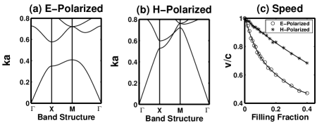
When the cylinders are placed regularly, the phenomenon of band structures prevails, and can be evaluated by the standard plane-wave expansion method. Fig. 1 shows the band structures for both E- and H- polarized EM waves when propagating through an array of square lattice of dielectric cylinders with radius cm, placed in the air. The dielectric constant for the cylinders is 10, which is smaller than that in Halevi1 . The fractional area occupied by the cylinders for a unit area , i. e. the filling factor, is 0.13. In the simulation, the frequency is made non-dimensional by scaling as . Here is shown that a complete bandgap appears for the E-polarized wave. Following Halevi1 ; Halevi2 , we also calculate the phase speed from the band structure for the first band as a function of the filling factor, and the results are shown in Fig. 1 (c). It is the linear region of the first band that we will consider in the following. The results indicate that the phase speed for the E-wave is more significantly reduced by the PC.
A PC made optical lens is illustrated in Fig. 2, which is in line with the prediction in Halevi1 . The source is placed at a distance far enough from the lens so that the incident waves can be regarded nearly as plane waves. In this way, the focusing point of the lens can be inferred from the transmitted field on the other side of the array.
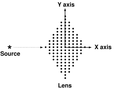
In the rest computation, the following parameters and arrangements are used: (1) Square lattices of cylinders and the propagation along [10] direction are considered; (2) the dielectric constant for the cylinders is 10; (3) the filling fraction is 0.13; (4) the radius of cylinders is 0.38 cm; (5) the frequency of the waves is taken as , well within the linear region; (6) the lens thickness, i. e. the max range along the -axis, is 10, and the height, i. e. the max span along the -axis, is 20; (7) the distance between the source and the center of the lens is 100. All the lengths are scaled non-dimensionally by the lattice constant.
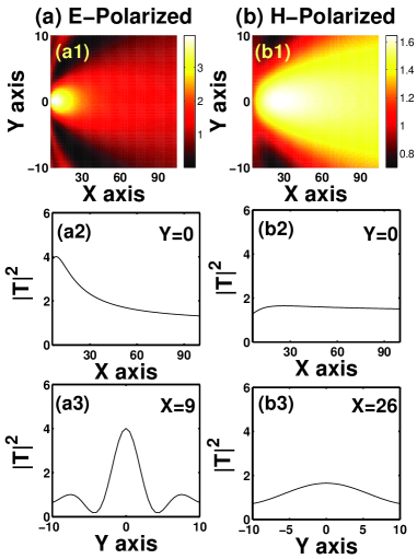
Fig. 3 shows the two-dimensional spatial distributions of the transmitted intensities. Here we see that although there are some focusing effects for both E- and H- polarized waves, the focusing effect is mostly prominent for the E-polarized wave in particular. This agrees with the expectation from the phase speed estimate in Fig. 1 (c): the phase speed for the E- polarized wave is more reduced, rendering a bigger contrast to the outside medium, thereby yielding a bigger refractive index. The focusing point of the E-polarized waves is at about , and the waves are better focused along the -axis. From the results in Fig. 3, we see that both E- and H- polarized waves have certain spreading along the x-axis, i. e. the propagation direction. This is very similar to what has been observed in the acoustic lensescervera ; Bikash . In any event, the fact that the focusing features are in certain qualitative agreement with the earlier predictionHalevi1 ; Halevi2 is encouraging. Another note should be made here. In Halevi2 , Halevi et al. conjectured an elliptically shaped lens using a 2D PC (See Fig. 1 in the paper). According to our earlier simulation on the acoustic lenses, a lens of such a shape is less efficient than the diamond-like lens illustrated by Fig. 2.
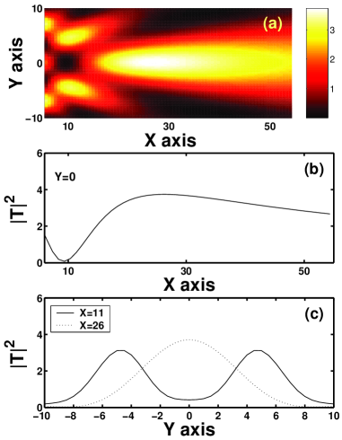
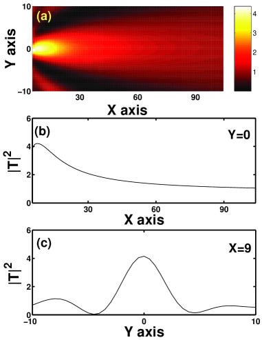
For comparison, we have also considered the E-polarized EM wave transmission in the [10] direction through a slab of rectangular array of dielectric cylinders. The size of the slab is : the length along the -axis is 10 and the height along the -axis is 20. The transmission results are shown in Fig. 4. Interestingly, there are some focusing effects. For example, there is a focused field centered around and there are other two focusing centers at and and respectively. This is quite different from the corresponding case with the acoustic arraysBikash . This seems not in the expectation. The reason follows. As the source is quite far away from the slab, the incident wave on the slab could be thought as a plane wave. Then it is expected that the transmitted wave should not be focused in the space when there is no such focusing effect as shown in LHM2 . The results in Fig. 4 together with that in Fig. 3 imply that although the focusing is quite a general feature of a lattice arrangement of dielectric cylinders, the shape of the lens as shown in Fig. 2 may be essential for a unique focusing.
We have also examined the robustness of the focusing against disorders. Here we consider the positional disorder of the cylinders. Since the wavelength is larger than the lattice constant in the present cases, one might intuitively conclude that the positional disorder has no effects. The results for the E-polarized wave are shown in Fig. 5. Here the shape of the array is the same as that in Fig. 2, except that the cylinders are placed in a complete randomness. Comparing to Fig. 3, it is shown that such a disorder does not destroy the focusing, in accordance with the intuition. That the disorder has little effect on the focusing of EM waves differs from the situation with the acoustic systems. In Bikash , it was shown that the disorders can completely destroy the focusing phenomenon in the acoustic lenses. All these results tend to support the homogenization which has been carried out in Halevi1 .
In summary, here we report the results of EM waves transmission through lenticular structures made of dielectric cylinders. Complying with the previous conjecture, the EM wave focusing effects are indeed observable by such structures.
Acknowledgements.
This work received support from National Science Council of Republic of China and the Department of Physics at the National Central University.References
- (1) E. Yablonovitch, J. Mod. Opt. 41, 173 (1994).
- (2) J. Joannopoulos, R. Meade, and J. Winn, Photonic Crystals (Princeton University Press, Princeton, NJ, 1995).
- (3) M. Sigalas and E. N. Economou, J. Sound Vib. 158, 377 (1992); J. P. Dowling, J. Acoust. Soc. Am. 91, 2539 (1992); M. S. Kushwaha, Recent Res. Devel. Appl. Phys. 2, 743 (1999).
- (4) E. R. Brown, C. D. Parker, and E. Yablonovitch, J. Opt. Soc. Am. B 10, 404 (1993); E. R. Brown, C. D. Parker, and O. B. McMahon, Appl. Phys. Lett. 44, 3345 (1994); E. R. Brown and O. B. McMahon, ibid. 68, 1300 (1996).
- (5) J. C. Chen, H. A. Haus, S. Fan, P. Villeneuve, and J. D. Jonnopoulos, J. Lightwave Technol. 14, 2575 (1996); S. Gupta, G. Tuttle, M. Sigalas and K. -M. Ho, Appl. Phys. Lett. 71, 2412 (1997).
- (6) P. W. Evans, J. J. Wierer, and N. Holonyak, Appl. Phys. Lett. 70, 1119 (1997).
- (7) S. -Y. Lin, V. M. Hietala, L. Wang, and E. D. Jones, Opt. Lett. 21, 1771 (1996); H. Kosaka et al. Phys. Rev. B 58, R10096 (1998).
- (8) S. -Y. Lin et al., Appl. Phys. Lett. 68, 3233 (1996); P. Rigby and T. F. Krauss, Nature (London) 390, 125 (1997).
- (9) T. F. Krauss, B. Vogele, C. R. S. Stanley, and R. M. de La Rue, IEEE Photonics Technol. Lett. 9, 176 (1997).
- (10) T. F. Krauss, O. Painter, A. Scherer, J. S. Roberts, and R. M. de La Rue, Opt. Eng. (Bellingham) 37, 1143 (1998).
- (11) H. Kosaka, et al., Phys. Rev. B 58, R10096 (1998)
- (12) R. A. Shelby, D. R. Smith, and S. Schultz, Science 292, 77 (2001).
- (13) C. Luo, S. G. Johnson, J. D. Joannopoulos, and J. B. Pendry, Phys. Rev. B 65, R201104 (2002).
- (14) J. Martorell, R. Vilaseca, and R. Corbalan, Appl. Phys. Lett. 70, 702 (1997).
- (15) P. Halevi, A. A. Krokhin, and J. Arriaga, Phys. Rev. Lett. 82, 719 (1999).
- (16) P. Halevi, A. A. Krokhin, and J. Arriaga, Appl. Phys. Lett. 75, 2725 (1999).
- (17) F. Cervera et al., Phys. Rev. Lett., 88, 023902 (2002)
- (18) B. Gupta and Z. Ye, Phys. Rev. E. in press.
- (19) Y. Y. Chen and Zhen Ye, Phys. Rev. Lett., 87, 184301 (2001).
- (20) V. Twersky, J. Acoust. Soc. Am. 24, 42 (1951).