Nanorheology : an Investigation of the Boundary Condition at Hydrophobic and Hydrophilic Interfaces.
Abstract
It has been shown that the flow of a simple liquid over a solid surface can violate the so-called no-slip boundary condition. We investigate the flow of polar liquids, water and glycerol, on a hydrophilic Pyrex surface and a hydrophobic surface made of a Self-Assembled Monolayer of OTS (octadecyltrichlorosilane) on Pyrex. We use a Dynamic Surface Force Apparatus (DSFA) which allows one to study the flow of a liquid film confined between two surfaces with a nanometer resolution. No-slip boundary conditions are found for both fluids on hydrophilic surfaces only. Significant slip is found on the hydrophobic surfaces, with a typical length of one hundred nanometers.
pacs:
47.15.Gf Low-Reynolds-number (creeping) flows and 68.35.-pSolid surfaces and solid-solid interfaces: structures and energetics1 Introduction
The hydrodynamic properties of a liquid at a solid interface are very important in a number of applications involving flows in confined geometries: tribology and lubrication, flows through porous media, or in microfluidic devices, etc. At a macroscopic scale, the no-slip boundary condition widely used to describe the flow of simple liquids at a solid surface is usually considered as very robust. However, it was suggested in early works of Schnell schnell56 and later of Churaev et al. Churaev84 that simple liquids may undergo substantial slip when flowing on non wetting surfaces. By measuring the water pressure drop in silanized glass capillaries of micrometric size the latter showed slip effects with a typical length of tens of nanometers. Such effects can not be neglected in flows at small scale, and the recent development of microfluidic devices has led to an increasing interest on this subject tretheway2002 ; cheng2002 .
At a microscopic scale, the hydrodynamic boundary condition (HBC) at a solid surface reflects the transfer of tangential momentum between the two phases. The influence of the liquid-solid interactions on the HBC has been addressed theoretically. These interactions can be characterized by the contact angle of the liquid on the solid surface. Molecular dynamic simulations by Barrat and Bocquet Barrat99a ; Barrat99b of Lennard-Jones liquids have shown that, when the liquid wets the solid surface, the no-slip boundary condition holds. On the contrary, in the case of partial wetting, slip effects of several molecular diameters occur: for a contact angle of , slipping lengths of about 10 nm are found Barrat99a ; Barrat99b . At high shear rate, (, where is the characteristic time of the Lennard-Jones potential) it has also been shown that the HBC may become non-linear and rate dependent Thompson97 . From an experimental point of view, investigations of flows at a submicronic scale have developped with experimental techniques such as Surface Force Apparatus (SFA), modified Atomic Force Microscopy (AFM) and fluorescence recovery methods. For a simple Newtonian liquid, it has been shown that the flow in films thicker than about ten molecular diameters can be described by the Navier-Stokes equations Horn85 ; Georges93 ; Klein2002 . The first experiments with SFA have also shown that, in a number of cases where the liquids wet the solid surfaces, the no-slip boundary condition holds. Studying the flow of alkanes over metallized surfaces of roughness close to 1 nm, Georges et al. Georges93 have shown that the no-slip boundary condition should be applied at, or very close to, the solid surface, at the scale of a molecular diameter. Previously, Chan and Horn Horn85 have obtained the same results for confined non polar liquid between atomically smooth mica surfaces. More recently, different research groups have studied various liquid-solid systems in both wetting and non-wetting conditions. They have reported various results either in the nature of the HBC or in the magnitude of the effects observed. We will summarize in Part V of this paper a number of such recent results.
In this paper, we use a Dynamic Surface Force Apparatus (DSFA) to compare the flow and the HBC of glycerol and water confined between hydrophilic (Pyrex) surfaces and hydrophobic silanized Pyrex surfaces. This SFA creates an oscillatory flow of very small amplitude and variable frequencies of a liquid confined between a sphere and a plane. The HBC is deduced from the force measured on the plane, caused by the flow of the liquid squeezed between the surfaces. We will first describe the dynamic SFA, then the experimental system and finally present our results. These are compared to previous measurements by other groups with different experimental techniques.
2 The experimental setup
The experimental setup is a new Dynamic Surface Force Apparatus (DSFA) that has recently been developed by our group. A schematic representation is given in Fig.1 and a more detailed description can be found in previous articles restagno2001 ; rsi2002 . This DSFA measures separately the relative displacement of the surfaces and the interaction force between them. The surfaces used are a plane and a sphere. The apparatus measures the static as well as the dynamic component of the forces when the sphere is moved towards the plane and can therefore be used as a nanorheometer. The sphere can be moved in a direction normal to the plane over a distance of about 2 m with a piezoelectric element . A piezoelectric element is used to superimpose to the quasistatic motion of the sphere a sinusoidal displacement of small amplitude at a frequency between 5 and 200 Hz.
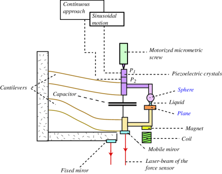
In the experiments reported here, a planar surface is fixed on a double spring cantilever of stiffness 1700 N/m. Its displacement is measured with a Nomarski interferometer, with a static resolution of 0.5 Å corresponding to 80 nN. The quasistatic displacement between the sphere and the plane is measured with a capacitive sensor with a 1 Å resolution. This capacitive sensor is calibrated for static and dynamic displacements before each experiment, with the help of the interferometer and of a coil/magnet system. The relative displacement of the surfaces is thus directly measured without using the calibration of the piezoelectric drivers. For dynamic measurements, the output signals of the sensors are connected to two digital two-phase lock-in amplifiers (Standford Research System SR830 DSP Lock In Amplifier) whose reference is used to drive the piezoelectric . In the dynamic regime, the capacitive sensor has a sensitivity of 2.10-12 m.Hz-1/2 and the optic sensor has a sensitivity of 8.10-9 N.Hz-1/2. Our measurements are performed with a bandwidth of 1 Hz. The phase resolution is 0.5o. The dynamic transfer fonction of the apparatus itself is measured for all frequencies when the surfaces are very far apart (no force). The dynamic component of the force is then deduced from the experimental signal, using this transfer fonction rsi2002 .
In this paper we will use the following notations: the displacement between the surfaces is
| (1) |
where is the quasistatic displacement of the surfaces with constant velocity (usually 1 Å/s) and the complex amplitude of the oscillatory component of the displacement. The interaction force is:
| (2) |
where is the quasistatic force of the surfaces and the complex amplitude of the oscillatory component of the force.
The norm and phase of the complex amplitudes and are determined using the procedure described above. The transfert function is defined as follows:
| (3) |
where and are respectively the stiffness and the damping induced by the confined liquid.
The signal being a displacement, it is necessary to specify the origin in order to get the actual distance between the surfaces. This origin is usually determined using the theory of adhesive contact (the JKR theory Johnson71 ). In this paper, the origin is only determined as the point where the repulsive force between the surfaces starts to raise (this only makes a difference of about 2 nm with the JKR determination, and sufficiently precise for our experiments ).
3 The experimental system
We have studied three systems with different wetting properties: glycerol on Pyrex, glycerol on silanized Pyrex, and water on silanized Pyrex.
The surfaces, a sphere with a millimeter diameter and a plane, are prepared as follows. The surfaces are washed in an ultrasonic bath with a detergent and distilled water. Then, they are rinsed with purified propanol, and, finally, they are passed through a flame. We have studied the surface of the plane with an atomic force microscope (Fig.2). The peak to peak roughness of the surfaces prepared in this way is about 1 nm on a surface of mm. The sphere is always plain Pyrex.
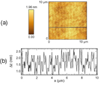
The silanized planes have been prepared by submerging our Pyrex surfaces (washed as explained above) in a mixture of 100 l of OTS (octadecyltrichlorosilane) and of 60 ml of toluene for about two hours. We then rinse the plane with chloroform. The AFM picture of surfaces prepared with this procedure is very similar to the one of plain pyrex planes (see Fig.2). The contact angles of macroscopic drops of water and glycerol have been measured on each type of solid surfaces and have been referred in Tab. 1. In each case the hysteresis of the contact angle is about .
| System | advancing contact angle |
|---|---|
| Glycerol-Pyrex | |
| Glycerol-silanized Pyrex | |
| Water-silanized Pyrex |
After having mounted the surfaces on the apparatus, we put a drop of liquid between the sphere and the plane. In the experiments with hydrophobic surfaces, only the plane is silanized. The experiments are carried out at ambient temperature, i.e., . The glycerol experiments are carried out in a dry atmosphere (some is in the same box than the DSFA).
4 Hydrodynamic force induced by a drainage flow between a sphere and a plane
We consider here the flow of a liquid between a sphere with a radius and a plane. The sphere is moving in the direction normal to the plane as shown in Fig.3.
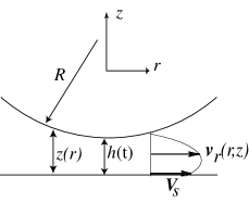
In the case of a no-slip boundary condition, the hydrodynamic force between the sphere and the plane due to the viscous dissipation is the so-called Reynolds force , which acts in the direction normal to the plane and reads:
| (4) |
where is the fluid viscosity, the distance between the apex of the sphere and the plane and the sphere velocity. With the no-slip boundary condition, the assumptions to obtain this result are that the liquid is incompressible, the solid surfaces ideally rigid, the Reynolds number of the flow is small, and the distance between the apex of the sphere and the plane is small in comparison with so that the lubrication approximation is valid.
In our experiments, we measure and . As mentioned in the previous paragraph, the displacement of the sphere towards the plane consists in two contributions: a quasi-static component and a sinusoidal component . is at most 5 Å. Given this value, one can consider that the distance in Eq.4 reduces to . Therefore in what follows we do not make any difference between these two notations. If the only force between the surfaces is the viscous one due to the Reynolds force, we have:
Thus in the case of a no-slip boundary condition, the inverse of the damping varies linearly with the distance between the surfaces, with a slope which is related to the shear viscosity of the liquid. The plot of versus is a straight line which intersects the -axis at its origin. If the elastic deformations of the surfaces are no longer negligible, or if the fluid is not incompressible, a real part should be present in the dynamic signals. As long as the dynamic signals remain purely imaginary, we can safely assume that those approximations hold.
If slippage occurs at the liquid-solid interface, the value or the tangential flow velocity at the solid surface is the slip velocity. If one assumes that the slip velocity is proportionnal to the hydrodynamic stress acting at the wall, can be expressed as a function of the local shear rate in terms of a slip length (or Navier length) Brillouin :
| (5) |
With a slip boundary condition, Eq.4 is no longer correct. Vinogradova Vino95 has calculated the expression of the viscous force between a sphere and a plane with a partial slip HBC described by Eq.5 :
| (6) |
where,
In this case, the plot of the inverse of the damping versus is no longer a straight line. However in the limit , the following expression for the asymptote is obtained :
| (7) |
Hence, for large distances, and in the case of partial slip at the solid wall, the plot of as a function of is a straight line translated by a distance compared to the no-slip case and intersecting the h-axis at the value . This is equivalent to applying the no-slip HBC inside the bulk of the solid at a distance of the surface, which gives a physical meaning of the slip length.
It is of interest to calculate the shear rate to which the liquid is submitted as a function of the sphere velocity and the gap . The actual shear rate in the fluid depends on the HBC. Nevertheless, it is possible to estimate an effective shear rate from the average velocity of the flow divided by the distance between the surfaces. This effective shear rate is small on the sphere-plane axis, and increases with the radial distance from the axis up to a maximum value :
| (8) |
obtained at the distance . At larger distances from the axis, the effective shear rate decays to zero. With mm, Hz, Å we have, for nm, s-1. In the following, we use Eq.8 to compare the typical shear rate obtained in different experiments involving a squeezing flow between a sphere and a plane (SFA and modified AFM).
5 Experimental results
5.1 Wetting case : glycerol over Pyrex
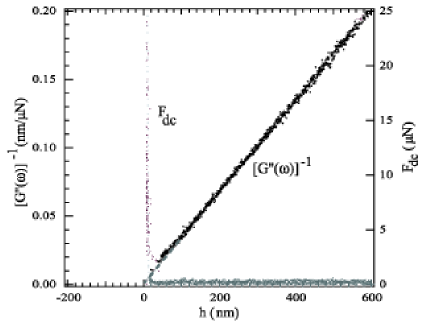
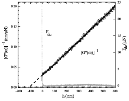
In Fig.4, we have plotted on the same graph the evolution of the inverse of the damping , and of the static interaction force as a function of , measured for a glycerol film confined between Pyrex surfaces. The measured dynamic force is here out of phase with the displacement excitation, so that a purely viscous force is obtained. As predicted by the theory in the case of a no-slip HBC, the plot of as a function of is a straight line. From the slope of this straight line we obtain the experimental value = 350 mPa.s of the liquid viscosity, which corresponds to the viscosity of glycerol containing a few percents of water at C. We have checked that this value is also obtained when the viscosity of glycerol is measured with a commercial rheometer under the same environmental conditions. The intersection of this straigth line with the -axis in Fig.4 corresponds to the zero given by the mechanical contact, i.e. when the static interaction force raises sharply. Therefore, we do not observe slip effects within the range of a few nanometers in this system.
5.2 Non wetting case
In Fig.5, we have plotted the same quantities as in Fig.4, but in the case of a glycerol film flowing between a silanized plane and a pyrex sphere. This is a typical result of what is obtained in this non wetting system. The plot of the inverse of the damping as a function of is a straigth line, whose slope is the same as that obtained in the wetting case. This shows that there is no bulk effect associated to the confinement of glycerol in this system. However the extrapolation of the straight line intersects the -axis at a negative distance of about 100 nm from the contact. This decrease of the hydrodynamic force shows the existence of liquid slippage occuring at the hydrophobic solid surface. The order of magnitude of the slip length is one hundred nanometers. Very similar hydrodynamic forces are obtained in the case of water confined between the same kind of surfaces (see Fig.6). In all these experiments, the frequency response is independent of the amplitude of excitation, of the speed of the quasi static motion of the surfaces (from 1 to 5 Å/s) and proportional to the excitation frequency (between 10 and 90 Hz). The hydrodynamic force measured is the same wether the two surfaces are separated from one another or brought together.
It must be stressed that we observe a significant variability of the slip lengths measured on different hydrophobic samples prepared with the same experimental procedure. The slip lengths measured may vary between 50 to 200 nm, which is one order of magnitude larger than the resolution of the experimental setup. This variability occurs only with the non-wetting samples, and has never been observed with Pyrex surfaces (wetting case).
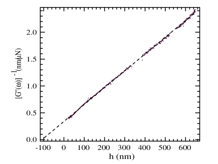
Table 2 summarizes some experimental results obtained by different research groups on the hydrodynamic boundary condition of simple liquids on various solid surfaces. These results show slip effects of different order of magnitude, with slip lengths significanly lower (Churaev84 ; Baudry2001 ; Craig2001 ) or significatly larger (Granick2001 ; tretheway2002 ) than the ones obtained in this study. The slip effects and slip lengths obtained in our experiment are of the same magnitude as the one observed by Pit et al. Pit2000 with hexadecane over a bare (wetting) or coated (partially wetting) sapphire surface. The major difference lays in the influence of the wetting properties of the surfaces. In our experiments slip occurs at the solid surface only on non-wetting samples, whereas Pit et al observe significant slip of hexadecane on a wetting atomically smooth sapphire surface. They also observe a no-slip condition on a rough heterogeneous lyophobic surface. The surface roughness is clearly an important parameter balancing the influence of wetting properties on the HBC. Hydrodynamic calculations have shown that for surfaces having locally the same HBC, the effect of roughness is to decrease the effective slip undergone by the flow Richardson73 . This effect of roughness may explain the differences between Pit’s results and ours regarding the influence of wetting properties on the HBC, although the slip lengths found are of same magnitude. However SFA experiments of Chan and Horn Horn85 on atomically smooth mica surfaces conclude on the no-slip boundary condition. Another important parameter may be the nature of the liquid. The results of Cheng et al obtained on surfaces whose wetting properties are unfortunately not specified, show slippage effects which increase with the liquid molecular size. The slip lengths found are of nanometer size, significantly lower than ours and Pit’s ones.
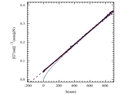
A more detailed comparison of our experimental data with macroscopic hydrodynamics shows that the hydrodynamic force measured in the non-wetting system is in general not fully compatible with a HBC corresponding to a well defined slip length as described by Eq.5. Indeed the theoretical curve in this case corresponds to the experimental data only in the asymptotic limit (see Fig.7). We do have no full explanation for that discrepancy. Such discrepancies at small distance have also been observed by Zhu and Granick Granick2001 in SFA experiments using hydrophobic OTE coated mica surfaces. They interpretate those discrepancies in terms of an effective slip factor (see Eq.6) depending on the liquid flow rate. This corresponds to a non-linear HBC. Such an interpretation is not possible in our experiments, since the hydrodynamic force varies linearly with the flow velocity, which can be varied either with the amplitude of the excitation (1 to 5 Å) or its frequency (10 to 90 Hz).
As far as the linearity of the HBC is concerned, it must be emphasized that other experiments involving a squeezing flow between a sphere and a plane with a partially wetting liquid-solid system, performed by Craig et al. Craig2001 , also show non linear slip effects which appear only at high velocities or small gap between the surfaces. It is however difficult to compare the hydrodynamic parameters in the different experiments with the sphere-plane geometry since they are done at different velocities (velocities in Granick2001 vary between 4 and 400 nm/s, in Craig2001 between 1 to 20 m/s, and in this work between 10 to 100 nm/s) but with different sphere radii (2 cm in Granick2001 , 10 m in Craig2001 , 1 mm in this work). In order to compare these different flow situations, we have indicated in Tab.2 the range of the typical shear rate in each experiment calculated from Eq. 8. It must be noted however that there is no experimental evidence that this effective shear rate is the hydrodynamic parameter controlling the occurrence of non-linear effects in the boundary condition. Zu’s experiments rather indicate a shear rate built on the surfaces velocity divided by the gap between them. Nevertheless the major difference between our experiment and the ones of Craig et al. and Zhu and Granick, is that we clearly observe slip effects at large distances and independantly of the flow velocity.
| Authors | Experimental | Solid surface | Liquids | Contact angle | Typical | Results | Typical |
|---|---|---|---|---|---|---|---|
| method | or wettability | shear rate | slip length | ||||
| () | |||||||
| Churaev | Pressure | Quartz + | Hg/plain quartz | to | 1-4 | Slip, linear HBC | 7010 nm |
| Churaev84 | drop | SAM of | Water | to | Slip, linear HBC | 3010 nm | |
| trimethyl- | CCl4 | No slip | 010 nm | ||||
| -chlorosilane | Benzene | No slip | 010 nm | ||||
| Cheng | Pressure | Glass & | Water | not measured | 700-5000 | No-slip | 0 nm |
| cheng2002 | drop | photoresist | Hexadecane | ” | Slip, linear HBC | 25 nm | |
| Decane | ” | Slip, linear HBC | 15 nm | ||||
| Hexane | ” | Slip, linear HBC | 8 nm | ||||
| Tretheway | PIV | Glass | Water | 200 | No-slip | 0 nm | |
| tretheway2002 | + SAM of OTS | ” | Slip | 1 m | |||
| Pit | FRAP | Bare saphire | hexadecane | , | 102-104 | Slip, linear HBC | nm |
| Pit2000 | + SAM OTS | ” | , | Slip, linear HBC | nm | ||
| + SAM FDS | ” | , | No slip | nm | |||
| Zhu | Dynamic | Bare mica | Tetradecane | 50-15.103 | No-slip | 0 nm | |
| Granick2001 | SFA | + ads.surfactant | Tetradecane | Non linear HBC | 0 to 1 m | ||
| + SAM of OTE | Tetradecane | Slip increases | 0 to 1.5 m | ||||
| + SAM of OTE | Water | with | 0 to 2.4 m | ||||
| Chan | SFA | Bare mica | Hexadecane | 50-500 | No-slip | 0 nm | |
| Horn85 | ” | Tetradecane | No-slip | ” | |||
| Baudry | Dynamic | Bare gold | Glycerol | 0.5-500 | No-slip | 0 nm | |
| Baudry2001 | SFA | + SAM of thiols | ” | Slip, linear HBC | nm | ||
| Craig | Modified | Gold | Sucrose solutions | , | 30-104 | Non linear HBC | 0 to nm |
| Craig2001 | AFM | + SAM of thiols | Slip increases | ||||
| with | |||||||
| This | Dynamic | Bare pyrex | glycerol | 0.5-500 | No-slip | 0 nm | |
| paper | SFA | + SAM of OTS | Glycerol | Slip, linear HBC | 50 to 200 nm | ||
| + SAM of OTS | Water | Slip, linear HBC | ” |
6 Conclusion
We have investigated with a dynamic surface force apparatus the flows of glycerol and water at a submicronic scale close to hydrophobic surfaces. These experiments show the existence of slip effects at the non-wetting solid wall which do not appear in flows close to a wetting Pyrex surface. The scale of the slip effect that we observe is of one hundred nanometers, and the hydrodynamic force is fully linear with the liquid velocity. These results are comparable qualitatively and quantitatively with other studies reported in the literature with different or similar experimental techniques Churaev84 ; Pit2000 ; Baudry2001 . They confirm that the wetting character of the liquid-solid system is very important for the flow properties at the solid interface.
However the hydrodynamic force is not fully compatible with an hydrodynamic boundary condition corresponding to a well defined slip length. We attribute this behavior to spatial heterogeneities in the local hydrodynamic boundary conditions, over the scale involved in the measurement of the hydrodynamic force with the flow geometry of the experiment - typically 50 m m. These spatial inhomogenities are specific to the hydrophobic surfaces, but we have not yet been able to correlate them to any direct observation with AFM measurements. However, using taping mode atomic force microscopy in water, Tyrell and Attard tyrell2001 have shown that in some conditions hydrophobic surfaces in water may be covered with flat nanobubbles extending laterally over hundreds of nanometers. The presence of such flat nanobubbles or thin films of air on hydrophobic surfaces, could be responsible for large slip effects with significant spatial variability Stone2002 . Further work is in progress for a better understanding of this effect.
We thank F. Feuillebois for helpful discussions, J. Klein for enlightening discussions and communications, J.-P. Rieu for help in imaging the surfaces. We thank the DGA for its financial support.
References
- (1) E. Schnell. J. Appl. Phys., 27:1149–1152, 1956.
- (2) N.V. Churaev, V.D. Sobolev, and A.N. Somov. J. Colloid and Interface Sci., 97:574–581, 1984.
- (3) D.C. Tretheway and C.D. Meinhart. Physics of Fluids, 14(3):L9–L12, 2002.
- (4) J.-T. Cheng and N. Giordano. Phys. Rev. E, 65:031206(1–5), 2002.
- (5) J.-L. Barrat and L. Bocquet. Faraday discussions, 112:119–127, 1999.
- (6) J.-L. Barrat and L. Bocquet. Phys. Rev. Lett., 82:4671–4674, 1999.
- (7) P.A. Thompson and S.M. Troian. Nature(London), 389:360–362, 1997.
- (8) D.C.Y. Chan and R.G. Horn. J. Chem. Phys., 83:5311, 1985.
- (9) J.-M. Georges, S. Milliot, J.-L. Loubet, and A. Tonck. J. Chem. Phys., 98:7345, 1993.
- (10) U. Raviv, S. Glasson, J. Frey, and J. Klein. J. Phys. : Condensed Matter, (publication scheduled in October 2002).
- (11) F. Restagno, J. Crassous, É. Charlaix, and M. Monchanin. Meas. Sci. and Tech., 12:16–22, 2001.
- (12) F. Restagno, J. Crassous, É. Charlaix, C. Cottin-Bizonne, and M. Monchanin. Rev. Sci. Instr., 73:2292–2297, 2001.
- (13) K.L. Johnson, K. Kendall, and A.D. Roberts. Proceedings of Royal Society of London A, 324:301–313, 1971.
- (14) L. Brillouin, Leçons sur la viscosité des liquides et des gaz. Gauthier-Villars, Paris, 1907.
- (15) O. Vinogradova. Langmuir, 11:2213–2220, 1995.
- (16) J. Baudry, É. Charlaix, A. Tonck, and D. Mazuyer. Langmuir, 17:5232–5236, 2001.
- (17) V.S.J. Craig, C. Neto, and D.R.M. Williams. Phys. Rev. Lett., 87(5):054504(1–4), 2001.
- (18) Y. Zhu and S. Granick. Phys. Rev. Lett., 87:096105–(1–4), 2001.
- (19) R. Pit, H. Hervet, and L. Léger. Phys. Rev. Lett., 85:980–983, 2000.
- (20) S. Richardson, J. Fluid Mech., 59:707-719, 1973.
- (21) E. Lauga and H. A. Stone, (to be published)
- (22) J.W.G. Tyrell and P. Attard. Phys. Rev. Lett., 87(17):176104–(1–4), 2001.