A scheme for electrical detection of spin resonance signal from a single-electron trap
Abstract
We study a scheme for electrical detection of the spin resonance (ESR) of a single electron trapped near a Field Effect Transistor (FET) conduction channel. In this scheme, the resonant Rabi oscillations of the trapped electron spin cause a modification of the average occupancy of a shallow trap, which can be detected through the change in the FET channel resistivity. We show that the dependence of the channel resistivity on the frequency of the rf field can have either peak or dip at the Larmor frequency of the electron spin in the trap.
pacs:
PACS Numbers: XXXXXThere has been a lot of interest recently in a few and single electron spin detection and measurement. The motivation comes primarily from quantum computing, where ability to manipulate and to measure single spin is the basis for several architecture proposals[1]. There is also significant interest in the study of local electronic environment, e.g. by means of local electron spin resonance. Such information would be valuable both for the conventional semiconductor industry, which has to deal with continuously decreasing feature sizes, as well as such novel research directions as spintronics where the utilization of electronic spin degrees of freedom may lead to conceptually new devices[2].
The main difficulty of a few spin detection and measurement lies in the inherent weakness of magnetic interaction, making direct measurement of a small number of spins challenging. Current state-of-the-art direct detection techniques, e.g. Magnetic Resonance Force Microscopy[3], have only recently achieved the sensitivity of about 100 fully polarized electron spins. An alternative approach is to convert spin dynamics into charge dynamics. Unlike single spin effects, single electron charge signals are much easier to measure. For instance, it is well established that the events of capture and release of electron by a single trap near conducting channel in a field effect transistor can be measured, either as a Random Telegraph Noise (RTS)[4, 5], or in charge pumping experiments[6]. Here we analyze a setup in which electron spin dynamics under electron spin resonance conditions is transformed into charge dynamics of the trap occupancy. This setup is motivated by the recent experiments of M. Xiao and H.W. Jiang[7], who analyze changes in the statistics of RTS jumps as a manifestation of the electron spin resonance.
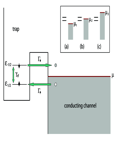
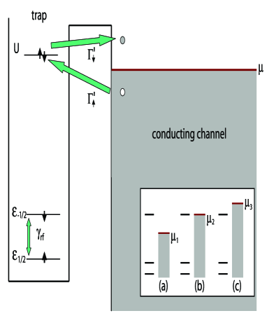
There is a variety of traps that can occur in real systems. Here we consider two representative cases schematically shown in Fig. 1 and Fig. 2. They correspond to the and “empty” states of the electron trap near the FET channel. The conduction channel chemical potential can be varied with a gate. The single electron levels in the trap are split by the external magnetic field , , where is the electron g-factor in the trap and is the Bohr magneton. There is an oscillating magnetic field , applied perpendicular to the field that couples the spin-split single-electron levels. The trap can accommodate up to two electrons. The main difference between the two cases, Fig. 1 and Fig. 2, is that in the presence of near-resonant rf field, the average electron occupancy of the spinless trap decreases, while for the spinful trap it increases. The change in the occupancy of the trap modifies the FET channel resistivity. The filling of the trap can cause both increase and decrease of the channel resistivity, depending on the initial charge state of the trap. Hence, there are four distinct combinations of the spin and charge states of the trap that lead to either enhancement or reduction of the FET channel resistivity at the resonance (Table I).
Both spinless and spinful trap cases (Fig. 1 and Fig. 2) can be modelled with the Anderson Hamiltonian
| (1) | |||
| (2) |
In Eq. (2) , where creates (annihilates) an electron with spin in the trap at the level . The second term in Eq. (2) represents Coulomb charging energy. are creation (annihilation) operators for the electrons in the channel. The fourth term describes tunneling transitions between the trap and the conduction channel. The tunneling amplitude can be evaluated from the parameters of the barrier using Bardeen’s formula [8], or directly from the experiment. The last term in Eq. (2), , is the coupling between the spin states in the trap produced by the rf field. If the rf frequency is close to that of Zeeman splitting in the trap, the can be written in the rotating wave approximation as
| (3) |
where , is the amplitude of the rf field. It is assumed that electrons in the conducting channel have g-factor different from the electronic g-factor in the trap (due to Rashba or lattice induced spin-orbit coupling). As a result, the influence of the rf field on the electronic states in the channel is “off-resonance” and therefore is neglected in Eq (3).
As mentioned earlier, even for the simple Anderson model of the trap, there are four distinct possibilities that correspond to different spin and charge “empty” states of the trap. For concreteness, we consider here two cases: (1) spinless positive trap, and (2) a neutral trap with spin. As we will see both produce a peak in channel resistivity under the ESR resonance conditions. The other two cases yield a dip.
Positive spinless trap— The positively charged trap, which essentially can be a donor impurity, can significantly influence the resistivity of the conducting channel. Indeed, when the trap is empty it is charged and therefore acts as a point Coulomb scatterer for the electrons in the channel. On the other hand, when the trap is filled, it is neutral, thus having relatively little effect on the channel resistivity [9]. The average (dc) resistivity of the channel can be written as
| (4) |
where and are channel resistivities with the single electron trap empty and filled, respectively, and is the probability for the trap to be empty (throughout the paper, denotes density matrix, not to be mistaken for conductivity). We will now demonstrate that due to the coherent effects in tunneling in and out of the trap induced by the rf magnetic field, the resistivity of the channel as a function of magnetic field develops a peak conditioned by , where is the frequency of the oscillating ESR magnetic field.
The inset in Fig. 1 shows three possible positions of the chemical potential with respect to the spin levels in the trap. In cases (a) and (c), where chemical potential lies below and above the two spin levels in the trap, tunneling into and out of the trap is prohibited. As a result, the electron occupation number for the trap is independent of the magnetic field at sufficiently low temperatures (for smaller than the separation between the chemical potential and the nearest spin level in the trap), i.e., the trap is never occupied in case (a) and always occupied in case (c). On the other hand, if the chemical potential is in between the two spin levels of the trap, case (b) in the inset, the resonant tunneling into and out of the trap is possible. That is, an electron with spin “up” in the channel can tunnel into the lowest Zeeman level in the trap, get transmitted into the upper Zeeman level by the rf field and consequently tunnel out of the trap into the unoccupied levels in the channel. This mechanism is shown schematically in Fig. 1. As a result, electronic occupation number in the trap becomes strongly modulated by the spin dynamics of the trap and therefore is strongly dependent on the magnetic field in the vicinity of the spin resonance condition.
From the Hamiltonian (2,3) one can derive quantum rate equations for the electronic occupation numbers in the trap. Similar calculations have been carried out for a system of two coupled quantum dots in contact with the Fermi liquid reservoirs [10]. Omitting technical details we quote the results of the calculations. We define density matrix for the electronic states in the trap by introducing density matrix elements and , which describe probabilities for the electron in the trap to occupy states with spin “up” and “down” respectively. We also define the off-diagonal element describing coherent superposition of the “up” and “down” spin states in the trap. Together with , the probability for the trap to be unoccupied, these form a set of coupled equations:
| (6) | |||
| (7) | |||
| (8) | |||
| (9) | |||
| (10) |
In the above equations , and , where is the electronic density of states in the conducting channel (constant for 2DEG) and the tunnel amplitudes are evaluated at energies of “up” and “down” spin states in the trap. We assume that the tunnel amplitudes vary on energy scale much larger than Zeeman splitting in the trap. Therefore in what follows we put , where is the life-time of the resonant level in the trap. In derivation of Eqs. (1) we have set .
Eqs. (1), though derived from the microscopic Hamiltonian (2), have transparent physical meaning. For example, in Eq. (6), the rate of change of is determined by the loss term – an electron from the conduction channel can tunnel into the trap with tunnel rate , while an electron in the trap can tunnel back into the channel with rate and generate a hole in the trap – the gain term in the RHS of Eq. (6). The diagonal density matrix elements are coupled with the off-diagonal elements in Eqs. (7)-(10) (the last terms in these equations) due to the rf component of the magnetic field that induces transitions between different spin states in the trap. These terms always appear in standard Bloch equations for a spin under magnetic resonance conditions [11].
The rate equations (1) can be solved for a stationary state, i.e., for . One finds that and, using Eq. (4), we obtain
| (11) |
Thus, the resistivity of the channel has a resonance when frequency of the rf field matches the Zeeman frequency of the electron in the trap, corresponding to the condition of single electron spin magnetic resonance. The width of the peak is equal to , i.e., it is determined by both the amplitude of the rf field and by the life-time of the electron in the trap. When , the height of the peak reaches its maximum (relative to , the value of resistivity away from the resonance).
Neutral trap with spin— A peak in the FET channel resistivity can be generated by a neutral trap as well. Consider a situation shown in Fig. 2. Here, the “empty” trap contains an electron that can occupy up or down spin states (with energies ). In addition, the trap can be occupied by two electrons with the total energy . The chemical potential now lies in the vicinity the two-electron state of the trap. This corresponds to the case (b) in the inset of Fig. 2. Similar to the previous section, the conversion of the ESR spin dynamics into changes of the trap occupancy is possible only if the absolute difference of the chemical potential in the channel and the energy level in the trap is smaller than half of the Zeeman splitting, i.e., . Then, if electron in the trap occupies level, another electron in the channel with opposite (up) spin can tunnel into the trap, so that two electrons in the trap occupy state with total energy . Such process is energetically allowed, provided . Next, an electron in the trap with spin “down” can tunnel out of the trap, thus leaving the remaining electron in the trap in spin “up” state. This process is also possible, as long as . Thus, the trap effectively relaxes its spin, creating a particle and a hole in the channel; see Fig. 2. The spin of the electron in the trap is subsequently flipped by the rf field, and so the process repeats.
The resistivity of the channel can now be expressed as
| (12) |
where and are resistivities of the trap containing one and two electrons respectively (), and is the probability for the trap to be occupied by two electrons. Again, from the Hamiltonian (2) we derive the rate equations for the trap
| (14) | |||
| (15) | |||
| (16) | |||
| (17) | |||
| (18) |
In Eqs. (12) ’s are defined above, while the tunnel rates . Assuming , Eqs. (12) can be solved for a stationary state. Then, substituting thus obtained into the Eq. (12), we find an expression for the resistivity similar to Eq. (11), but with and interchanged and replaced by . Thus, the resistivity of the channel as a function of magnetic field again has a peak centered at .
Effects of spin relaxation— Effects of environment, such as phonons, nuclear spins, etc., can be taken into account by introducing additional relaxation rate, in the equations for the off-diagonal elements of the spin (here we neglect the longitudinal spin relaxation, i.e., ). Note, that the noise spectra that induce must be taken at the Rabi (), and not zero, frequency[11]. Thus, replacing rates and in Eqs. (10, 18) by and , and repeating the above algebra, we obtain the resistivity of the channel in the presence of externally induced spin dephasing
| (19) |
for the positively charged trap, while for the neutral trap is obtained by replacing and in the above equation by and . Eq. (19) shows that the height of the peak in the resistivity decreases due to the suppression of the spin coherence by the externally induced dephasing rate , and the peak width becomes .
Rabi oscillations of a single electron trap — The electrical detection of Rabi oscillations from a single trap can also be performed under the conditions described above. Rabi oscillations correspond to the coherent weight transfer between the states of a two level system. Therefore, in the case of the spinless trap at the ESR resonance, the probability to tunnel out of the trap between times and after the trapping, , is periodically modulated at the Rabi frequency (here we assumed that there is no extrinsic dephasing, ). Since the current between the trapping and escape events remains constant, the current power spectrum can be easily calculated as
| (20) |
for . In case the externally induced dephasing dominates, in the above expression should be replaced by .
In summary, we proposed a mechanism for electrical detection of electron spin resonance from a single electron trapped near the conducting channel of a field effect transistor. The dc effect is based on the modification of the average trap occupancy caused by the resonant excitation of the trap. Depending on the charge and spin propertied of the empty trap, at the resonance, the channel resistivity can both increase and decrease, an effect that can be used for trap diagnostics. We also propose a scheme for the Rabi oscillation detection in the same system.
| neutral or negative | positive | |
|---|---|---|
| spinless | dip | peak |
| spinful | peak | dip |
Acknowledgements— This work was supported by the U.S. DOE and DARPA SPINs program. D.M. was supported in part by the NSF grants DMR-0121146 and ECS-0102500.
REFERENCES
- [1] B. Kane, Nature (London) 393, 133 (1998); R. Vrijen et al., Phys. Rev. B 62, 012306 (2000); G. Burkard and D. Loss, Phys. Rev. B 59, 2070 (1999); D. Mozyrsky, V. Privman, and M.L. Glasser, Phys. Rev. Lett. 86, 5112 (2001); J. Šmakov, I. Martin, and A.V. Balatsky, Phys. Rev. Lett. 88, 037003 (2002).
- [2] S.A. Wolf et al., Science 294, 1488 (2001).
- [3] J. A. Sidles , Phys. Rev. Lett. 68, 1124 (1992); D. Rugar et al., Science 264, 1560 (1994); Z. Zhang, P. C. Hammel, and P. E. Wigen, Appl. Phys. Lett. 68, 2005 (1996).
- [4] K. S. Ralls and R. A. Buhrman, Phys. Rev. Lett. 60, 2434 (1988).
- [5] M.-H. Tsai, H. Muto, and T.P. Ma, Appl. Phys. Lett. 61, 1691 (1992).
- [6] G.V. Groeseneken, et al., IEEE Trans. Electr. Dev. 43, 940 (1996).
- [7] M. Xiao and H.W. Jiang, unpublished.
- [8] J. Bardeen, Phys. Rev. Lett. 6, 57 (1961).
- [9] If electrons in the channel are polarized, the resistivity can be also weakly modulated by the relative orientation of the electronic spin in the trap and of the conduction electron spin in the channel due to their exchange interaction.
- [10] A. N. Korotkov, D. V. Averin, and K. K. Likharev, Phys. Rev. B 49, 7548 (1994); S. A. Gurvitz and Ya. S. Prager, Phys. Rev. B 53, 15932 (1996); S. A. Gurvitz, Phys. Rev. B 56, 15215 (1997).
- [11] A. Abragam, The principles of nuclear magnetism (Clarendon Press, Oxford, 1961).