Left-Handed Surface Waves in a Photonic Structure
Abstract
It is demonstrated that an isotropic left-handed medium can be constructed as a photonic structure consisting of two dielectric materials, one with positive and another with negative dielectric permittivities . Electromagnetic waves supported by this structure are the surface waves localized at the dielectric interfaces. These surface waves can be either surface phonons or surface plasmons. Two examples of negative materials are used: silicon carbide and free-electron gas.
keywords:
41.20.Jb 42.70.Qs 54.40.Db,
1 Introduction
Left-handed materials (LHMs) [1] with negative magnetic permeability and dielectric permittivity have recently attracted a great deal of attention because of their promise for developing novel lenses and low reflectance surfaces [2, 3]. LHMs have a negative refractive index, which implies that the phase and group velocities of the propagating electromagnetic wave oppose each other. This property of LHMs is responsible for their anomalous physical behavior: reversed sign of the Doppler effect and counter-intuitive refraction at the interface with the ”normal” (right-handed) media [1].
Since materials with negative refraction index do not naturally occur, they have to be artificially constructed. An LHM in the microwave frequency band was recently constructed as an array consisting of metal rods and split-ring resonators [4]. Using the same strategy for designing LHMs at much shorter wavelengths (e. g., in the infrared part of the spectrum) may prove challenging. Here I describe a new idea of making a LHM photonic structure by utilizing surface waves at the interfaces of dielectrics with opposing signs of . Left-handedness of such structures is due to the existence of the surface waves at the vacuum/dielectric interfaces. Practical implementation of such photonic structures at a micron scale is encouraged by the availability of low-loss dielectrics and semiconductors with negative , including many polar crystals such as SiC, LiTaO3, LiF, and ZnSe. The frequency-dependent dielectric permittivity of these crystals, given by the approximate formula [5] is negative for . Note that reduces to that of the free electron gas for and .
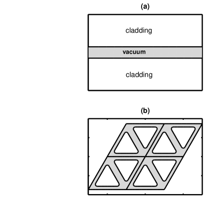
In Section 2 I review the properties of surface waves in a single waveguide (SW) with cladding shown in Fig. 1(a), derive the effective dielectric permittivity and magnetic permeability , and demonstrate that the phase and group velocities of the surface waves can oppose each other. Waveguide with silicon carbide (SiC) cladding is used as an example of a medium which supports left-handed surface phonons.
In Section 3 the triangular lattice photonic waveguide (TLPW) shown in Fig. 1(b) is found to be a perfectly isotropic LHM for small wavenumbers , where is the lattice periodicity. The triangular cladding regions shown in Fig. 1(b) are assumed to have with the frequency dependence of a free electron gas. In this example, vacuum/cladding interfaces support left-handed surface plasmons. Recently [6], it has been suggested that the group velocity in LHMs is not aligned with the phase velocity, making the perfect lens [2] impossible. I demonstrate that this is not the case even for an artificially constructed LHM such as the TLPW.
2 Single waveguide with negative cladding
To illustrate how a negative can be mimicked in a single waveguide, consider electromagnetic wave propagation in the horizontal () direction assuming a piecewise constant dielectric constant: in the vacuum channel (for ) and inside the cladding (for ). The goal is to explain how the energy can flow in the negative direction (and so ) whereas the phase velocity . Consider a confined transverse magnetic (TM) wave with non-vanishing components such that at midplane . Since we are interested in the wave propagation along , introduce integrated over the transverse direction quantities
From Faraday’s and Ampere’s laws, assuming that and integrating by parts, obtain, correspondingly, and , where the effective dielectric permittivity and magnetic permeability of the waveguide are defined as follows:
| (1) |
The definition of the weight-averaged is intuitive, and is defined so as to eliminate the longitudinal component of the electric field which does not contribute to the power flow along the waveguide. For note that and are, on average, out of phase if , making the wave left-handed. The resulting dispersion relation is . Therefore, and must be of the same sign for a propagating wave. The propagating mode is left-handed if , necessitating that the dielectric constant of the cladding be negative.
and are calculated by solving the eigenvalue equation for :
| (2) |
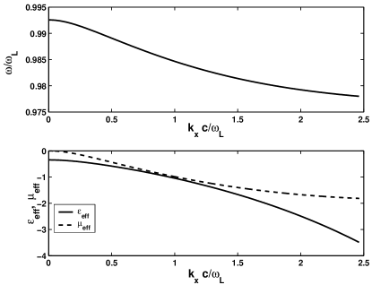
where . As an example, consider silicon carbide (SiC) cladding with , , and [7]. SiC has a stopband (region of negative ) in the far infrared, m. The dispersion relation and the corresponding and are plotted in Fig. 2(a,b) for a SW with the vacuum gap width . The propagating surface mode in a SW exhibits left-handedness: it’s group velocity is negative, and so are and . The cutoff at is caused by the vanishing of the .
Why is despite ? The total Poynting flux along the dielectric waveguide is the sum of the fluxes inside the cladding and in the vacuum gap. In the gap, and are in phase, so . Inside the cladding reverses its sign across the vacuum/cladding interface because (continuity of ). Because is continuous across the interface, in the cladding. For a narrow gap, the integrated Poynting flux is negative. Note that not any surface wave is left-handed. Achieving left-handedness requires that (a) the frequency of the mode lie within the stopband of the cladding, (b) there are two interfaces, and (c) the vacuum gap between the interfaces is small. In the case of SiC cladding, the left-handed waves are surface phonons.
3 Triangular Lattice Photonic Waveguide
The single waveguide example was used to explain the emergence of left-handedness of the surface waves, and to derive the necessary conditions (a-c) for their existence. The objective of this paper is to construct an isotropic photonic medium capable of transmitting left-handed waves in all directions. This is accomplished by constructing a Triangular Lattice Photonic Waveguide (TLPW) which consists of the triangular pieces of dielectric cladding arranged in a triangular lattice, as shown in Fig. 1(b). We assume that the dielectric permittivity of the cladding is the same as that of a free electron gas: .
Every propagating wave in the TLPW is characterized by its wavenumber , and can be represented as . Here is periodic on the boundaries of the elementary cell of the triangular lattice shown as an equilateral parallelogram in Fig. 3. For each value of Eq. (2) is solved for its eigenvalues using a commercial finite elements code FEMLAB [8], yielding the dispersion relation v. s. . The local and cell-averaged Poynting fluxes are computed for each solution.
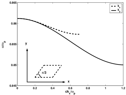
Simulations results indicate that TLPW is perfectly isotropic for small well inside the Brillouin zone. The elementary cell of the TLPW and the dispersion relation v. s. for two orthogonal directions of are shown in Fig. 3. The two dispersion curves, which are identical for (establishing the isotropy), are drawn to the respective edges of the Brillouin zone: and [9].
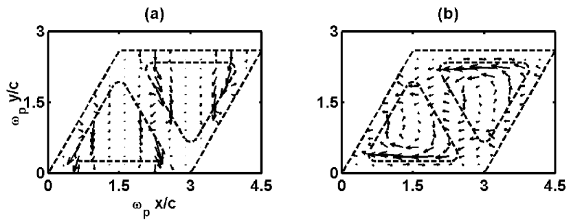
These two directions are chosen because they exhibit the maximum possible anisotropy. Indeed, for there exists a vacuum/cladding interface along which the electromagnetic energy can flow in direction, Fig. 4(b). No such interface exists for , Fig. 4(a). Thus, the local Poynting flux patterns are very different for these two directions, as can be seen by comparing Figs. 4(a,b). For the parameters of Fig. (4), , the index of refraction is . Index of refraction can be readily tuned in both directions by adjusting the parameters of the TLPW: periodicity and channel width .
Despite the differences in the flow patterns, the cell-integrated fluxes are identical for all directions of , and so are the frequencies: . Numerical results unambiguously confirm that, for small , phase and group velocities exactly oppose each other. At least for this particular LHM, the claim of Valanju et. al. [6] that is not confirmed. Anisotropy for large is merely the consequence of the periodicity of the photonic structure.
In conclusion, it was demonstrated that surface waves (phonons or plasmons) at the interface of dielectrics with opposing signs of the dielectric permittivity can be left-handed. An isotropic composite medium which has a negative refraction index with respect to such waves can be constructed as a photonic structure.
References
- [1] V. G. Veselago, Sov. Phys. Uspekhi 10 (1968) 509.
- [2] J. B. Pendry, Phys. Rev. Lett. 85 (2000) 3966.
- [3] D. R. Smith and N. Kroll, Phys. Rev. Lett. 85 (2000) 2933.
- [4] D. R. Smith, W. J. Padilla, D. C. Vier, S. C. Nemat-Nasser, and S. Schultz, Phys. Rev. Lett. 84 (1999) 4184.
- [5] Kittel, Introduction to Solid State Physics, John Wiley Sons, New York (1976).
- [6] P. M. Valanju, R. M. Walser, and A. P. Valanju, Phys. Rev. Lett. 88, 187401 (2002).
- [7] W. G. Spitzer, D. Kleinman, and D. Walsh, Phys. Rev. 113 (1959) 127.
- [8] FEMLAB Reference Manual, Version 2.2, November 2001, Comsol AB, Sweden.
- [9] E. I. Smirnova et. al., J. Appl. Phys 91, 960 (2002).