Diffraction theory and focusing of light by left-handed materials
Abstract
A diffraction theory in a system consisting of left-handed and right-handed materials is proposed. The theory is based upon the Huygens’s principle and the Kirchhoff’s integral and it is valid if the wavelength is smaller than any relevant length of the system. The theory is applied to the calculation of the smearing of the foci of the Veselago lens due to the finite wavelength. We show that the Veselago lens is a unique optical instrument for the 3D imaging, but it is not a “superlens” as it has been claimed recently.
keywords:
negative refraction, left-handed materials, ,
In his seminal work Veselago [1, 2] has introduced the concept of left-handed materials (LHM’s). In a simplest case the LHM’s are materials with simultaneously negative electric permittivity and magnetic permeability in some frequency range. In the LHM the vectors form a left-handed set, while in the usual materials (, ) they form a right-handed set. If imaginary parts of and are small, the electromagnetic waves (EMW’s) propagate in the LHM but they have some unusual properties. All these properties originate from the fact that in the isotropic LHM the Poynting vector is anti-parallel to the wave vector .
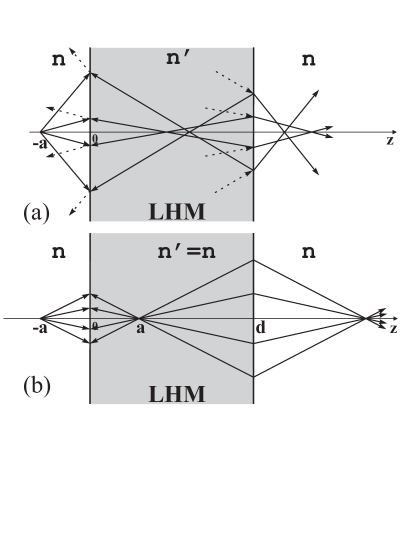
Consider a propagation of the EMW from a point source located at the point through an infinite slab of the LHM with the thickness and a usual right-handed material (RHM) at and (Fig.1). It is obvious that everywhere at because the energy propagates from its source. The directions of vector for different rays are shown by arrows. They should be chosen in such a way that at both interfaces tangential components of vector for incident, reflected and refracted waves are the same. Another condition is that the component should be parallel to in the RHM and anti-parallel in the LHM. Then in the LHM is negative. It follows that the Snell’s law for the RHM-LHM interfaces has an anomalous form: , where and are the angles of incidence and refraction respectively, and are positive refractive indexes for LHM and RHM respectively. The angles of reflection are equal to the angles of incidence.
The device shown at Fig.1(b) is a unique optical lens proposed by Veselago. In this lens and , then and . It is easy to show that in this case the reflected wave is completely absent. Since all the rays going right from the source have , all of them have foci at points and as shown in Fig.1(b).
All the ideas above have been put forward by Veselago about years ago[1, 2]. Recently the method of fabricating of the LHM’s on the basis of metallic photonic crystals has been found and the San Diego group has reported the first observation of the anomalous transmission [3] and even the anomalous Snell’s law [4]. Both observations have been interpreted as a result of negative and .
One can see that the Veselago lens, shown at Fig.1(b), is an absolute instrument because it images stigmatically a three-dimensional domain and the optical length of any curve in the object space is equal to the optical length of its image[5]. Note, that the definition of the absolute instrument assumes geometrical optics only. Since the LHM’s have been already obtained we think that the Veselago lens can be extremely important device for the 3D imaging.
Pendry [6] claims that the Veselago lens has another unique property. Due to Pendry the resolution of this lens does not have a traditional diffraction limitation which follows from the uncertainty principle. Pendry has introduced a new term “superlenses” with the Veselago lens as a first representative of this class. Several works have recently appeared where the concept of superlenses was criticized [7, 8, 9, 10]. On the other hand, Ziolkowski and Heyman [11] proposed a refined version of Pendry’s analysis which confirms his result. Haldane [12] interpreted results of Pendry in terms of surface waves described by Ruppin [13]. Haldane also proposed a way how to overcome some mathematical inconsistencies of papers [6, 11], shown before in [14, 10]. Haldane claims that even though the perfect focusing is impossible the diffraction limit can be defeated.
In this paper we propose a general scalar theory of diffraction in the LHM which is based upon the Huygens’s principle and the Kirchhoff’s integral. As any diffraction approach our theory works under condition that the wavelength is much smaller than any relevant geometrical length in the problem. We apply this theory to the Veselago lens and calculate the smearing of the foci due to the finite wavelength. Thus, our result does not support the idea of “superlens”.
The Green function for the Helmholtz equation for the LHM, which describes propagation of a spherical wave from a point source, has a form , where and is a distance from the source. At a small element of the sphere the spherical wave can be considered as a plane wave which is characterized by the Poynting vector and wave vector both with the radial component only. Since is directed along the external normal to the surface element, the wave vector in the LHM is directed along the internal normal. It is easy to see that our Green function obeys these properties.
Following the principles of the scalar theory of diffraction[15] the field at the observation point can be written in a form of a surface integral
| (1) |
where is the length of the vector from the point to the surface element, is the projection of the surface element on the plane perpendicular to the direction of the ray coming from the source to , is a constant for any LHM. To find one can consider a plane wave with the wave vector normal to the infinite plane of integration. Since this plane is fictional, the constant can be found from the condition that the Huygens’s principle in the form Eq.(1) reproduces the same plane wave. Doing the calculations similar to Ref.[15] one gets , so that for the LHM the constant has a different sign than the similar constant for the RHM.
The Huygens’s principle can be applied to any interface which has a curvature larger than the wavelength. It gives the correct direction of refracted waves but it does not give the amplitudes of both refracted and reflected waves. However, it can be successfully applied to the Veselago lens where reflected waves are absent.
Note, that there are other methods to describe the diffraction which may be also used if the source of the rays is unknown. They are described and compared in details in Jackson’s textbook [16]. One can show that all the methods give the same result at .
Moreover, the Kirchhoff integral Eq. (1) may be considered as a hint to get a solution, valid at large . The function as given by Eq. (1) is meaningful only at the distances from the interface larger than the wavelength. Nevertheless, if we consider solution obtained for these distances exactly at the interface, we find that it satisfies proper boundary conditions. Namely, is continuous and changes sign at the interface (See[11]).
Now we apply Eq.(1) to the Veselago lens. To find the field inside the slab we shall integrate in Eq.(1) over the plane . The field in this plane is produced by a point source and has a form
| (2) |
The field inside the slab can be found using Eq.(1) with a constant instead of because now we are integrating over the RHM-LHM interface rather than over the fictional surface in the LHM. In a similar way at the LHM-RHM interface one should use a constant . Using the method described in Ref.[15] it is easy to show that and . Thus one gets
| (3) |
where the additional factor is the cosine of the angle between the ray, coming from the source to the point and the unit vector in direction. One can see that the optical lengths for all rays (the sum of exponents in the integrand of Eq.(3)) from the point source to the focus, located at , , are zero and the value of the field at the focal point , while the geometrical optics gives an infinite field in this point. To find in the vicinity of the focus one should expand the integrand in Eq.(3) near the point assuming , and , where . Then one gets
| (4) |
where . Equation (4) gives
| (5) |
At one gets an analytical expression
| (6) |
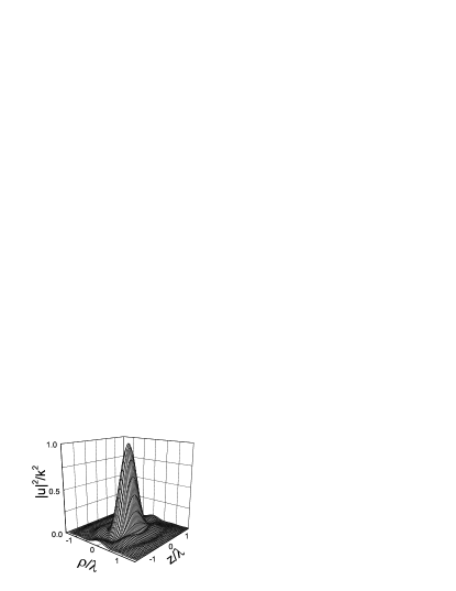
Another analytical expression can be obtained at : . The same result has been obtained in Ref. [10]. Figure 2 shows dimensionless function as given by Eq.(5). One can see that the smearing of the focus is anisotropic. The half-width in direction is approximately one wavelength while in direction it is approximately twice as less.
Now we find the field in the close vicinity of the second focus located at , . The general expression for at differs from Eq.(3). One should apply the Huygens’s principle to both interfaces located at and . Then the expression for the field has a form
| (7) |
To calculate these integrals in the vicinity of the second focus using inequalities , one should introduce new variables instead of variables by relations
| (8) |
One can see from Eq.(7) that at optical lengths of all rays exiting from the point source at and coming to the second focus at are equal to zero. Thus the new variables describe deviation from the geometrical optics and they should be small. Introducing the new variables and expanding the exponents in Eq.(7) one can get an expression for the field in the vicinity of the second focus. For , one gets
| (9) |
where the function is given by Eq.(3). In other words, the smearing of the in the second focus is the same as the smearing in the first one.
Our result has a simple interpretation in terms of uncertainty principle. One can see that the main contributions to the integrals in Eqs.(3,7) come from a circle of a radius in the - plane around axis. Thus, the effective aperture of the Veselago lens is of the order of . The uncertainty of the lateral momentum is of the order of , which gives the smearing of the foci of the order of .
Now we compare our results with the analytical calculations of Pendry [6] and Ziolkowski and Heyman [11]. Our paper is valid for large only while in [6, 11] the near field region is also considered. The main difference between our works is that in Ref.[11] the incident spherical wave is expanded into series of the plane waves in the plane. This series contains the evanescent waves (EW’s) which are claimed to provide the “superlensing”. The matching of these plane waves at the interfaces is done independently. Note that each EW has the Poynting vector in the plane of the lens, which does not correspond to the problem under study. Moreover, the superposition of the EW’s diverges within three-dimensional domain [10, 12, 14] at large values of . This happen because their amplitudes increase as with positive . Haldane[12] argues that the “ultra violet cutoff” for this problem exists, but it is outside macroscopic electrodynamics, so that upper value of is very large. However, even with the cutoff the solution looks strange. The field is exponentially large within the domain which occupies all the space between the two foci. The field in each focus has a different limit from the left and from the right side. Therefore, we do not think that such a solution means a perfect focusing.
Finally, we have proposed the theory of diffraction in a system, consisting of the LHM and the RHM and have applied this theory to the calculation of the smearing of the foci of the Veselago lens. This smearing is of the order of the wavelength.
References
- [1] V. G. Veselago, Sov. Phys.-Solid State 8 (1967) 2854.
- [2] V. G. Veselago, Sov. Phys. Uspekhi 10 (1968) 509.
- [3] D. R. Smith et al., Appl. Phys. Lett. 75 (1999) 1425.
- [4] R. A. Shelby, D. R. Smith, S. Schultz, Science 292 (2001) 77.
- [5] M. Born, E. Wolf, Principle of Optics, Pergamoon Press, Oxford, 1980, p. 143.
- [6] J. B. Pendry, Phys. Rev. Lett. 85 (2000) 3966.
- [7] G. W. ’t Hooft, Phys. Rev. Lett. 87 (2001) 249701.
- [8] J. M. Williams, Phys. Rev. Lett. 87 (2001) 249703.
- [9] P. M. Valanju et al., Phys. Rev. Lett. 88 (2002) 187401–1.
- [10] N. Garcia et al., Phys. Rev. Lett. 88 (2002) 207403–1.
- [11] R. W. Ziolkowski, E. Heyman, Phys. Rev. E 64 (2001) 056625.
- [12] F. D. M. Haldane, cond-mat/0206420.
- [13] R. Ruppin, J. Phys.: Condens. Matter 13 (2001) 1811.
- [14] A. L. Pokrovsky, A. L. Efros, cond-mat/0202078.
- [15] D. L. Landau, E. M. Lifshitz, Electrodynamics of Continuous Media, Pergamon Press, Oxford, 1960, p. 196.
- [16] J. D. Jackson, Classical Electrodynamics, Willey & Sons, New York, 1998, p. 598.