Imaging the Near Field
Abstract
In an earlier paper we introduced the concept of the perfect lens which focuses both near and far electromagnetic fields, hence attaining perfect resolution. Here we consider refinements of the original prescription designed to overcome the limitations of imperfect materials. In particular we show that a multi-layer stack of positive and negative refractive media is less sensitive to imperfections. It has the novel property of behaving like a fibre-optic bundle but one that acts on the near field, not just the radiative component. The effects of retardation are included and minimized by making the slabs thinner. Absorption then dominates image resolution in the near-field. The deleterious effects of absorption in the metal are reduced for thinner layers.
I Introduction
Conventional optics is a highly developed subject, but has limitations of resolution due to the finite wavelength of light. It has been thought impossible to obtain images with details finer than this limit. Recently it has been shown that a ‘perfect lens’ is in principle possible and that arbitrarily fine details can be resolved in an image provided that the lens was constructed with sufficient precision. The prescription is simple: take a slab of material, thickness , and with electrical permittivity and magnetic permeability given by,
| (1) |
Given that these conditions are realised, the slab will produce an image of any object with perfect resolution. The key to this remarkable behaviour is that the refractive index of the slab is,
| (2) |
It was Veselago in 1968 [1] who first realised that negative values for would result in a negative refractive index and he also pointed out that such a negative refractive material (NRM) would act as a lens but it took more than 30 years to realise the concept of negative refractive index at microwave frequencies [2, 3, 4, 5].
It was only in recent times [6] that the lens’s remarkable property of perfect resolution was noted. For the first time there is the possibility of manipulating the near field to form an image. The physics of negative refractive index has caught the imagination of the physics community as evidenced by the publications in the past two years [4, 5, 6, 7, 8, 9, 10, 11, 12, 13, 14, 15]
Although the conditions for a perfect lens are simple enough to specify, realising them is in practice rather difficult. There are two main obstacles. First the condition of negative values for also implies that these quantities depend very sensitively on frequency so that the ideal condition can only be realised at a single carefully selected frequency. Second it is very important that absorption, which shows up as a positive imaginary component of or , is kept to a very small value. Resolution of the lens degrades rapidly with increasing absorption. It is the objective of this paper to explore how the effects of absorption can be minimised.
Let us probe a little deeper into the operation of the perfect lens. Any object is visible because it emits or scatters electromagnetic radiation. The problem of imaging is concerned with reproducing the electro-magnetic field distribution of objects in a two dimensional (2-D) plane in the 2-D image plane. The electromagnetic field in free space emitted or scattered by a 2-D object (x-y plane) can be conveniently decomposed into the Fourier components and and polarization defined by :
| (3) |
where the source is assumed to be monochromatic at frequency , and is the speed of light in free space. Obviously when we move out of the object plane the amplitude of each Fourier component changes (note the z-dependence) and the image becomes blurred. The electromagnetic field consists of a radiative component of propagating modes with real and a near-field component of non-propagating modes with imaginary whose amplitudes decay exponentially with distance from the source. Provided that is real, , it is only the phase that changes with z and a conventional lens is designed to correct for this phase change. The evanescent near-field modes are the high-frequency Fourier components describing the finest details in the object and to restore their amplitudes in the image plane requires amplification, which is of course beyond the power of a conventional lens and hence the limitations to resolution.
Thus the Perfect lens performs the dual function of correcting the phase of the radiative components as well as amplifying the near-field components bringing them both together to make a perfect image and thereby eliminating the diffraction limit on the image resolution. In general the conditions under which this perfect imaging occurs are :
| (4) |
where and are the dielectric permittivity and magnetic permeability of the NRM slab, and and are the dielectric permittivity and magnetic permeability of the surrounding medium respectively.
An important simplification of these conditions can be had in the case that all length scales are much less than the wavelength of light. Under these circumstances electric and magnetic fields decouple: the P-polarised component of light becomes mainly electric in nature, and the S-polarised component mainly magnetic. Therefore in the case of P-polarised light we need only require that , and the value of is almost irrelevant. This is a welcome relaxation of the requirements especially at optical frequencies where many materials have a negative values for , but show no magnetic activity. We shall concentrate our investigations on these extreme near field conditions and confine our attentions to P-polarised light.
In Section-2, we investigate the properties of a layered structure comprising extremely thin slabs of silver and show that layered structures are less susceptible to the degrading effects of absorption, than are single element lenses. In section-3, we present some detailed calculations of how the multilayer lens transmits the individual Fourier components of the image.
II The layered perfect lens - an unusual effective medium
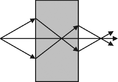
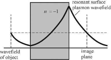
Reference to figure 2 shows that extremely large amplitudes of the electric field occur within the lens when the near field is being amplified. This is especially true for the high frequency Fourier components which give the highest resolution to the image. Unless the lens is very close to the ideal lossless structure, these large fields will result in dissipation which will kill the amplifying effect. However there is a way to restructure the lens to ameliorate the effects of dissipation. We observe that in the ideal lossless case we can perfectly well divide the lens into separate layers each one making its contribution to the amplification process (Shamomina et al have made a similar observation [14] and Zhang et al. have considered a similar system [15]). Provided that the total length of vacuum between the object and image is equal to the total length of lens material, the lens will still work and produce a perfect image. However this subdivision of the lens makes a big difference to how the lens performs when it is less than ideal and absorption is present. The point is that by distribution the amplification, the fields never grow to the extreme values that they do when the lens is a single slab and therefore the dissipation will be much less. Figure 3 illustrates this point.
First let us estimate the resolution of a lens constituted as a single slab. According to our original calculations [6] in the near field limit the transmission coefficient through the lens for each Fourier component is,
| (5) |
where,
Obviously when,
| (6) |
the lens’ power to amplify begins to fall away. Fourier components of higher spatial frequency do not contribute and hence the resolution is limited to,
| (7) |

The easiest way to investigate the properties of a layered system is to recognise that, provided that the slices are thin enough, it will behave as an effective anisotropic medium whose properties we calculate as follows. Applying a uniform displacement field, , perpendicular to the slices gives electric fields of and in the positive dielectric medium and in the negative material of the lens respectively. Therefore the average electric field is given by,
| (8) |
where
| (9) |
is the effective dielectric function for fields acting along the -axis. By considering an electric field along the -axis we arrive at
| (10) |
where is the effective dielectric function for fields acting along the -axis. We have assumed for simplicity that the thickness of each material component is the same, but it is also possible to have unequal thicknesses. Now under the perfect lens conditions, , we have
| (11) |
Thus the stack of alternating extremely thin layers of negative and positive refractive media in the limiting case of layer thickness going to zero behaves as a highly anisotropic medium.
Radiation propagates in an anisotropic medium with the following dispersion,
| (12) |
and hence for the perfect lens conditions it is always true that,
| (13) |
Each Fourier component of the image passes through this unusual medium without change of phase or attenuation. It is as if the front and back surfaces of the medium were in immediate contact.
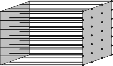
Here we have a close analogy with an optical fibre bundle where each fibre corresponds to a pixel and copies the amplitude of the object pixels to the image pixels without attenuation and with the same phase change for each pixel, preserving optical coherence. Our layered system performs exactly the same function with the refinement that in principle the pixels are infinitely small, and the phase change is zero. In figure 5 we illustrate this point with an equivalent system: an array of infinitely conducting wires embedded in a medium where . In the latter case it is more obvious that an image propagates through the system without distortion. Indeed in the trivial zero frequency limit the system simply connects object to image point by point.
Coming back to our point that the layered system reduces the effect of absorption, we estimate the transmission for P-polarized light through such a system in the near field limit as
| (14) |
Evidently for small values of the transmission coefficient is unity and these Fourier components contribute perfectly to the image, but for large values of transmission is reduced. We estimate the resolution limit to be,
| (15) |
Therefore the smallest detail resolved by the lens decreases linearly with decreasing absorption (). In contrast the original single slab of lens had a much slower improvement of resolution, being inversely as . Thus it appears to be a case of two lenses are better than one but many lenses are the best of all.
III Image Simulations for a multilayer stack
In the previous section we gave some qualitative arguments as to the properties of metal-dielectric multilayer stacks and is clear that for P-polarized light in the quasi-static limit this structure would behave as a near-perfect ‘fibre optic bundle’. In the electrostatic (magnetostatic) limit of large , there is no effect of changing () for the P(S)-polarization. The deviation from the quasi-static limit caused by the non-zero frequency of the electromagnetic wave would, however, not allow this decoupling. When the effects of retardation are included, a mismatch in the and from the perfect-lens conditions would always limit the image resolution and also leads to large transmission resonances associated with the excitation of coupled surface modes that could introduce artifacts into the image[16]. For the negative dielectric (silver) lens, the magnetic permeability everywhere, and this is a large deviation from the perfect lens conditions. The dispersion of these coupled slab plasmon polaritons and their effects on the image transfer has been extensively studied in Ref. [13].
Essentially, for a single slab of negative dielectric material which satisfies the conditions for the existence of a surface plasmon on both the interfaces, the two surface plasmon states hybridise to give an antisymmetric and a symmetric state, whose frequencies are detuned away from that of a single uncoupled surface state. The transmission as a function of the transverse wave-vector remains reasonably close to unity up to the resonant wave-vector for the coupled plasmon state, after which it decays exponentially with larger wavevectors. The secret for better image resolution is to obtain a flat transmission coefficient for as large a range of wave vectors as possible. This is possible by using a thinner slab in which case the transmission resonance corresponding to a coupled slab mode occurs at a much larger . For the transfer of the image over useful distances, we would then have to resort to a layered system of very thin slabs of alternating positive and negative media.
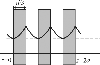
Let us now consider a layered system consisting of thin slabs of silver (negative dielectric constant ) and any other positive dielectric medium (). Since the dielectric constant of silver is dispersive***An empirical form for the dielectric constant of silver in the visible region of the spectrum is , ( in eV). The imaginary part can be taken to be reasonably constant in this frequency range., we can choose the frequency () of the electromagnetic radiation so as to satisfy the perfect lens condition at the interfaces between the media (). We use the transfer matrix method[17] to compute the transmission through the layered medium as a function of the transverse wave-vector at a frequency at which the perfect lens condition is satisfied. We will denote by the number of slabs with negative dielectric constant in the alternating structure, each period consisting of a negative and positive slab as shown in figure 4. Now the total length of the system is where is the period of the multilayer stack (the negative and positive slabs being of equal thickness of ). Note that the total thicknesses of positive and negative dielectric media between the object plane to the image plane are also equal.
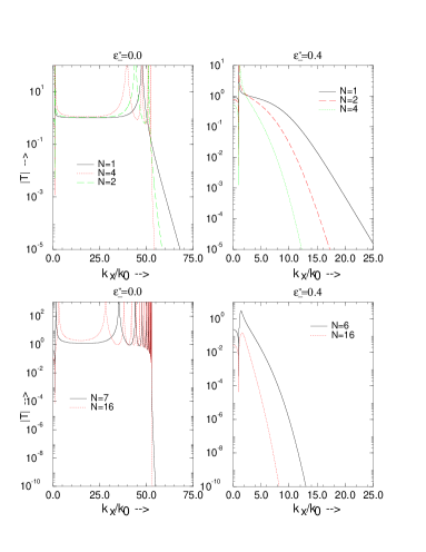
The transmission across the multilayer system is shown in figure 6, where the thickness of the individual slabs is kept constant, but the number of layers is increased, thereby increasing the total length of the system. We get divergences in the transmission at wave-vectors corresponding to the coupled plasmon resonances. The number of the resonances increases with the number of layers, corresponding to the number of surface modes at the interfaces. For the system with the (hypothetical) lossless negative media, one notes that as we increase the number of layers, the transmission coefficient is almost constant and close to unity with increasing , until it passes through the set of resonances and decays exponentially beyond. The range of for which the transfer function is constant is independent of the total number of layers and depends only on the thickness of the individual layers which sets the coupling strength for the plasmon states at the interfaces. In the presence of absorption in the negative medium, however, the decay is extremely fast for the system with larger simply as a consequence of the larger amount of absorptive medium present. Also note that the absorption removes all the divergences in the transmission. As noted by us in earlier publications, the absorption is actually vital in this system to prevent the resonant divergences which would otherwise create artifacts that dominate the image.
Next we keep the total length of the stack fixed and change the number of layers. In the lossless case, the range of for which there is effective amplification of the evanescent waves, simply increases with reducing layer thickness as can be seen in figure 7. Of course, the number of transmission resonances which depend on the number of surface states increases with the number of layers. With absorptive material, however, the transmission decays faster with for larger in the case of the thicker slabs (10nm) than in the case of the thinner slabs (5nm). This reconfirms our analytical result that the effects of absorption would be less deleterious for the image resolution in the case of thinner layers. Note that the total amount of absorptive material in this case is the same in both the cases.


In any case, the absorption in the negative dielectric (metal) appears to set the ultimate limit on the image resolution in this case of the layered medium. We have noted earlier in Ref. [13] that the effects of absorption could be minimised by using a large dielectric constant, GaAs say (), for the positive medium and tuning to the appropriate frequency where the perfect lens condition is satisfied for the real part of the dielectric constant of the metal. In the case of silver, the imaginary part of the permittivity or the absorption is reasonably constant (0.4) over the frequency range of interest. Hence, it is immediately seen that the fractional deviation from the perfect lens condition in the imaginary part is smaller when the real part of the permittivity is large and hence the amplification of the evanescent waves becomes more effective. Now we show the transmission obtained across a multilayer stack where and , corresponding to alternating slabs of silver and GaAs, in figure 8. We must first note that the wavelength of light at which the perfect lens condition for the permittivity of silver is satisfied is different in the two cases. Using the empirical formula for the dispersion of silver, we obtain at 356 nm and at 578 nm. In figure 8 for the lossless system, the transmission resonances appear to occur at higher values of for the high index system, but it must realised that is smaller in this case and the corresponding image resolution would actually be lower. However, when we compare the transmission with absorption included, the beneficial effects of using the larger value of the dielectric constant become obvious. The transmission coefficient indeed decays much more slowly with in this case. Also note that we have taken the source to be in air and the image to be formed inside the high-index dielectric medium.
Finally, we show in figure 9 the images of two slits of 15nm width and a peak-to-peak separation of 45 nm obtained by using a single slab of silver as the lens and a layered medium of alternating layers of silver and a positive dielectric medium as the lens. The total distance from the object plane to the image plane in both cases is 80 nm. The images of the slits in the case of the single slab lens are hardly resolved, whereas the images of the slits are well separated and clearly resolved in the case of the layered lens. The enhancement in the image resolution for the layered lens is obvious from the figure. The bump seen in between the slits is an artifact due to the fact that the transmission function is not exactly a constant for all wave-vectors.

IV Conclusions
We have elaborated the design of the perfect lens by considering a multilayer stack and shown that this has advantages over the original configuration of a single slab of material. In particular the effects of absorption are much reduced by the division into mutilayers. The limiting case of infinitesimal multilayers was also considered and shown to be equivalent to an effective medium through which the image propagates without distortion as if it were conveyed by an array of very fine infinitely conducting wires. We went on to make a detailed analysis of how imperfections in the lens affects the image quality. The effects of retardation and the coupled slab plasmon resonances can be minimized by considering very thin layers of 5 to 10 nm thickness. The effects of absorption then dominate the image transfer, but are less deleterious when the individual layer thicknesses are smaller. The effects of absorption can also be minimized by using materials with higher dielectric constants, and tuning the frequency of the radiation to meet the perfect lens conditions.
Acknowledgments
SAR would like to acknowledge the support from DoD/ONR MURI grant N00014-01-1-0803.
REFERENCES
- [1] Veselago, V.G., 1968, Sov. Phys. Uspekhi, 10, 509.
- [2] Pendry, J.B., Holden, A.J., Robbins, D.J., and Stewart, W.J.,
- [3] Pendry, J.B., Holden, A.J., Stewart, W.J., and Youngs, I., 1996, Phys. Rev. Lett., 76, 4773; Pendry, J.B., Holden, A.J., Robbins, D.J., and Stewart, W.J., 1998, J. Phys.: Condens. Matter, 10, 4785.
- [4] Smith, D.R., Padilla, W.J., Vier, D.C., Nemat-Nasser, S.C., and Schultz, S., 2000, Phys. Rev. Lett., 84, 4184.
- [5] Shelby, R.A., Smith, D.R., and Schultz, S., 2001, Science, 292, 77.
- [6] Pendry, J.B., 2000, Phys. Rev. Lett., 85, 3966.
- [7] Pendry, J.B., 2001, Physics World 14, 47.
- [8] Ruppin, R., 2000, Phys. Lett. A, 277, 61; Ruppin, R., 2001, J. Phys.: Condens. Matter, 13, 1811.
- [9] Markos, P., and Soukoulis, C.M., 2002, Phys. Rev. B 6 5, 033401; (cond-mat/0105618).
- [10] Lindell, V., Tretyakov, S.A., Nikoskinen, K.I., and Ilvonen, S., 2001, Microwave Opt. Tech. Lett. 31, 129.
- [11] Tretyakov, S.A., 2001, Microwave Opt. Tech. Lett. 31 , 163.
- [12] Caloz, C., Chang, C.-C., and Itoh, T., 2001, J. Appl. Phys. 90, 5483.
- [13] Ramakrishna, S.A., Pendry, J.B., Smith, D.R., Schurig, D., and Schultz, S., 2002, J. Mod. Optics (In press).
- [14] Shamonina, E., Kalinin, V.A., Ringhofer, K.H., and Solymar, L., 2001, Electron. Lett. 37, 1243.
- [15] Zhang, Z.M., and Fu, C.J., 2002, Appl. Phys. Lett. 80, 1097.
- [16] Smith, D.R., Schurig, D., Rosenbluth, M., Schultz, S., Ramakrishna, S.A., and Pendry, J.B., 2001, (Unpublished).
- [17] Born, M., and Wolf, E., Principles of Optics, 6th Ed. (Pergamon Press, Oxford, 1989).