[
Pore Stabilization in Cohesive Granular Systems
Abstract
Cohesive powders tend to form porous aggregates which can be compacted by applying an external pressure. This process is modelled using the Contact Dynamics method supplemented with a cohesion law and rolling friction. Starting with ballistic deposits of varying density, we investigate how the porosity of the compacted sample depends on the cohesion strength and the friction coefficients. This allows to explain different pore stabilization mechanisms. The final porosity depends on the cohesion force scaled by the external pressure and on the lateral distance between branches of the ballistic deposit . Even if cohesion is switched off, pores can be stabilized by Coulomb friction alone. This effect is weak for round particles, as long as the friction coefficient is smaller than 1. However, for nonspherical particles the effect is much stronger.
pacs:
PACS numbers: 02.70.Ns, 45.70.Cc, 62.25.+g]
I Introduction
Cohesion plays an important role in modern powder and nano technology. It determines the compaction and sintering behaviour as well as the mechanical properties like yield under shear stress [1] An important tool to understand the behaviour microscopically is the modelling on the particle scale, i.e. discrete element methods [2].
So far most computational studies have neglegted cohesion between particles. This is justified in dry systems on scales where the cohesive force is weak compared to the gravitational force on the particle, i.e. for sand and coarser material, which collapses under its own weight into a random dense packing. Powders already show cohesion effects: With decreasing grain diameter cohesive forces lead to highly porous media. For particle diameters in the nanometer range the cohesive force becomes the dominant force, so that particles stick together upon first contact.
When sintering nano-powders care has to be taken that the grains do not grow. This is achieved in so-called sinter forging under high pressure at relativly low temperatures [3]. In this process the highly porous powder gets compacted. In order to simulate this compaction process we use the contact dynamics method, which in principle [4] allows perfectly rigid particles with Coulomb friction [5, 6] without regularization of these force laws. Whereas in soft particle molecular dynamics there already exist cohesion models [7, 8, 9, 10], in contact dynamics cohesive models are just at the beginning [11, 12, 13].
Here we present contact dynamics results for two dimensional systems of round particles, which can be realized in experiments by aggregates of parallel cylinders [14]. Cohesion as well as rolling friction were included, which turns out to be crucial to describe the high porosity of nano powders. In three dimensions, torsion friction is needed in addition [15]. Here we explain how the different contact properties contribute to stabilizing the pores.
II Contact Dynamics Simulaton
A Without Cohesion and Rolling Friction
It is believed that the physics of dry dense granular matter with many lasting contacts is determined by volume exclusion and Coulomb friction. Both contact laws are nonsmooth, i.e. they do not determine the forces as functions of state variables (positions and velocities). The forces at a nonsliding contact are reaction forces in the sense that they have to compensate all external forces which would violate the constraints of volume exclusion and zero relative velocity. The contact dynamics method [16, 6, 5] is designed such that it determines these constraint forces in every time step. Elastic deformations of the particles need not be taken into account, hence the choice of the simulation time step is not coupled to the stiffness of the particles as it is in soft particle molecular dynamics.
For two particles in contact, the constraint force can be determined analytically, if the externally applied forces are known. But typical dense systems consist of many particles involving many contacts forming contact networks, and calculating all contact forces is a global problem, because the force at a contact influences the neighboring contacts and so on. To find a solution (which is not necessarily unique, cf. e.g. [17]), usually an iterative procedure is applied: The force at each contact is calculated in random order by considering the preliminary forces of adjacent contacts as already correct (which allows the same treatment as for external forces). This iteration goes on until a convergence criterion is fulfilled. A sensible choice is to demand the relative force changes at every contact to be below a given treshold during a certain number of consecutive iterations.
B Cohesion Model


In this section the cohesion model we use (“normal cohesion”) is described. For simplicity it has only two parameters, a constant attractive cohesion force in normal direction, which acts over a short range determining the cohesion energy (Fig. 1). The particles are still considered as perfectly rigid: The cohesive interaction does not deform them. A contact can only open, if an external pulling force exceeds the threshold and performs work larger than , so that the particles separate with a kinetic energy . While Radjai et al. [11] use the same cohesion model, Jean et al. [12] proposed a different implementation, the FCR model, which has more parameters.
The introduction of a force scale into Signorini’s condition (Fig. 1) leads to a numerical complication. This is related to the existence of “shocks”: Because of the perfect rigidity of the particles, a finite momentum can be transmitted instantaneously, if the connected cluster of particles, to which the contact belongs, collides with some other particle or cluster. This corresponds to an infinite normal contact force in form of a Dirac-pulse . Due to the time discretization by steps of , though, one gets a finite during the time-step containing the shock, which cannot be distinguished from a force evolving continuously at a lasting, non-shocked contact. Whereas for shocks and persisting contacts can be treated in the same manner [5], it depends on , whether a contact with given and opens or not, if it is shocked (). For large it may happen, that drops below the threshold , so that the contact cannot open. Indeed we find that the number of contacts which open in a simulation run decreases with increasing .
However, this is not the only source of systematic errors related to the discrete time step: Probably most important is that the iterative determination of the forces is only accurate within a given tolerance, so that the constraints are not perfectly obeyed. Hence a time step in general leads to a small overlap between the particles, which depends on . The third systematic error occurs in time steps during which a contact opens. As the cohesion force is acting over the whole time step, although is reached some time in between, the cohesion energy dissipated during opening the contact is slightly overestimated. All three systematic errors become smaller for smaller time steps.
As an example the final piston position as a result of a simulation of uniaxial consolidation by a fixed external force is shown in Fig.3 as a function of the time step. For decreasing time step the simulation result systematically increases. In our simulations in the next sections we use a time step , which leads to an average overlap between the particles of about 5% of their radius. This explains why in Fig.3 the final piston position for is about 5% smaller than the extrapolated value at . To get a lower percentage one would have to use smaller time steps which leads to an increase of computation time. We only compare simulation results which were obtained with the same time step.

We also did quasistatic simulations, where shocks are eliminated by resetting the velocities to zero after every time step. Then the results are different from the case of finite compaction speed: One gets more porous structures within the compaction process by a piston with an external load. Due to neglecting inertia effects the system’s reaction force onto the piston is below the external force on the piston at any time. In the “end” both forces are almost equal, but a low difference is left leading to a sustained movement of the piston. Thus, the final static configuration as found in the simulations presented in this paper, cannot be reached via a quasistatic simulation in finite computation time. This simulation methods would be applicable for simulating systems under constant strain only.
The opening of a contact needs usually several time steps, in which the pulling force exceeds . The pulling force minus has to perform the work necessary to reach the distance , where the contact breaks. In our model a contact which started to open, but at which has not yet been reached, is not pulled back by the cohesive force, if the pulling force becomes weaker than (concerning nano-particles a sinter neck which was pulled by an external force to a thinner neck is not built up to its former width again without sintering). Such a weakened but not yet broken contact can only be strengthened again (decrease of ), if the particles are pushed together externally.
For comparison we also did some simulations with a cohesion model, in which the cohesion force is able to pull the particles together again, if the contact had not been broken. A contact which has been slightly opened by an external force (i.e. forces from the other contacts on the particles) is pulled back to zero gap between the particles again (the normal force not exceeding the threshold ). As a result a contact, which did not break, has a chance to relax, instead of remaining weakened. Simulating this model gives similar results as presented in this paper. The main difference is due to the roughness of the upper envelope of the ballistic deposits which we choose as initial configuration for the simulation of the compaction process (Fig. 8). For high cohesion values the system really stays nearly unchanged, whereas in the simulations presented in the following the system compacts, until the upper envelope has become flat.
Cohesion does not only counteract the opening of a contact but also hinders it to become sliding. Therefore the Coulomb friction law needs to be modified. In order to avoid introducing additional parameters, we assume that the Coulomb friction is simply raised to like in [11] (Fig. 2). An alternative modification would be to increase the friction coefficient depending on . In Sec. III we show, that this by itself would lead to the stabilization of pores even if “normal cohesion” would be absent.
C Rolling Friction Model

In the case of round particles, rolling of two particles on each other must be considered. Its special importance in the context of cohesive contacts (as opposed to purley repulsive particles) can be explained as follows: Cohesion leads to stabilization of chains (i.e. particles with a coordination number of two), and thus allows for a less compact structure. The latter effect, however, is possible only if rolling is suppressed, otherwise the chains are floppy and will fold.
Introducing rolling friction to the model means to allow for a local torque. But in principle, the point contact formed by two adjacent rigid discs (or spheres) cannot exert a torque. This may be compared to the fact that the microscopic origin of Coulomb’s law of friction is not obvious for a contact with zero area. In both cases we regard the dimensions of the contact area and deformation zone as negligibly small compared to the particles.
The condition for rolling is similar to Coulomb’s law for sliding (Fig. 2): The contact can bear a local torque up to the threshold (cf. Fig. 4). If this is exceeded, the contact becomes a rolling one and hence exhibts a local relative angular velocity . According to experimental results [18], the coefficient for rolling friction is not chosen to be velocity dependent as it would be for a viscoelastic material [19], but is regarded as a phenomenological material constant which includes a (microscopical) length scale.
For the simulations shown in the following, we consider only discs of identical size and mass. Only then the equations of motion for the relative angular velocity on the one hand, and for the relative translational velocity on the other, are not coupled, which simplifies the implementation of rolling friction significantly.
III Simulations Results
A Initial Configuration
In principle there are two general methods to produce nano-particles: the first is to fracture bulk material. The second one builds nano-particles by chemical precipitation or condensation in a liquid or gas environment. While the production in large quantities is usually done in liquids, the production in the gas phase has some advantages (higher pureness of the material and sharper grain size distribution).
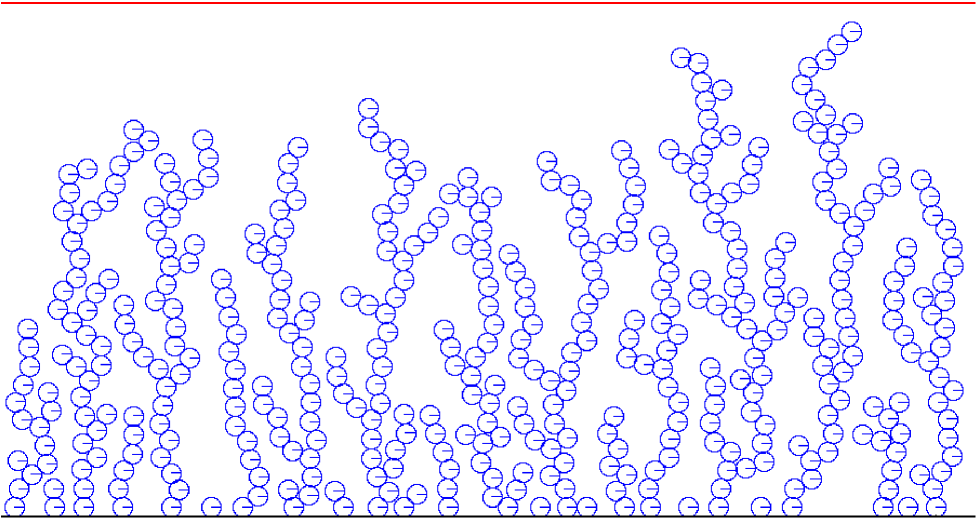
To extract nanoparticles out of a gas flow one can use a filter where the particles are deposited on. Simulations of the filter process by a fiber network show a finger-like structure of the deposit [20, 21]. Similar structures are obtained on a flat surface by ballistic deposition: Particles fall from the top randomly and stick to the first particle they reach within a capture radius around the particle. Such a ballistic deposit is shown in figure 5 for two dimensions [22]. These structures are not fractal, i.e. the porosity is not depending on the system size but on the capture radius.

The capture radius is a measure for the average distance between the branches so that the volume fraction of a ballistic deposit increases about linearly with the reciprocal of the capture radius (Fig. 6). For monodisperse spherical particles the minimum capture radius is two particle radii, i.e. the minimal distance between the centers of mass two particles can have. In the following sections different ballistic deposits with periodic boundary conditions in lateral direction are compacted by a piston with constant load in vertical direction.
B Influence of different contact properties

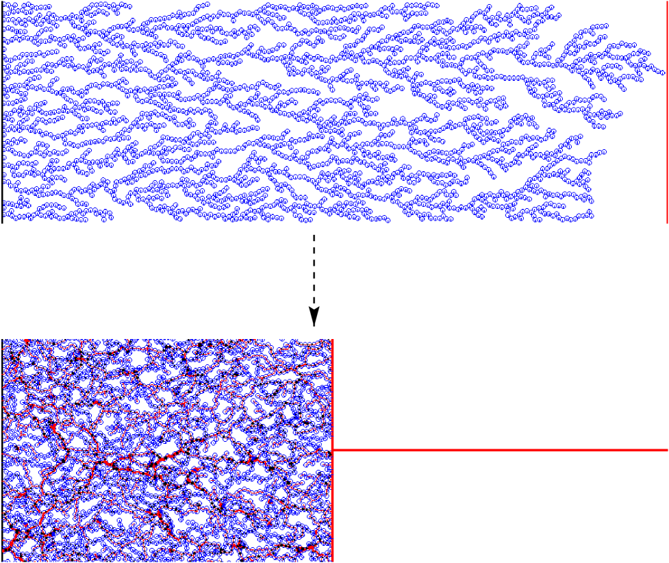
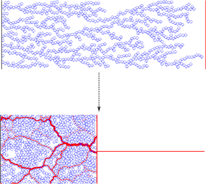
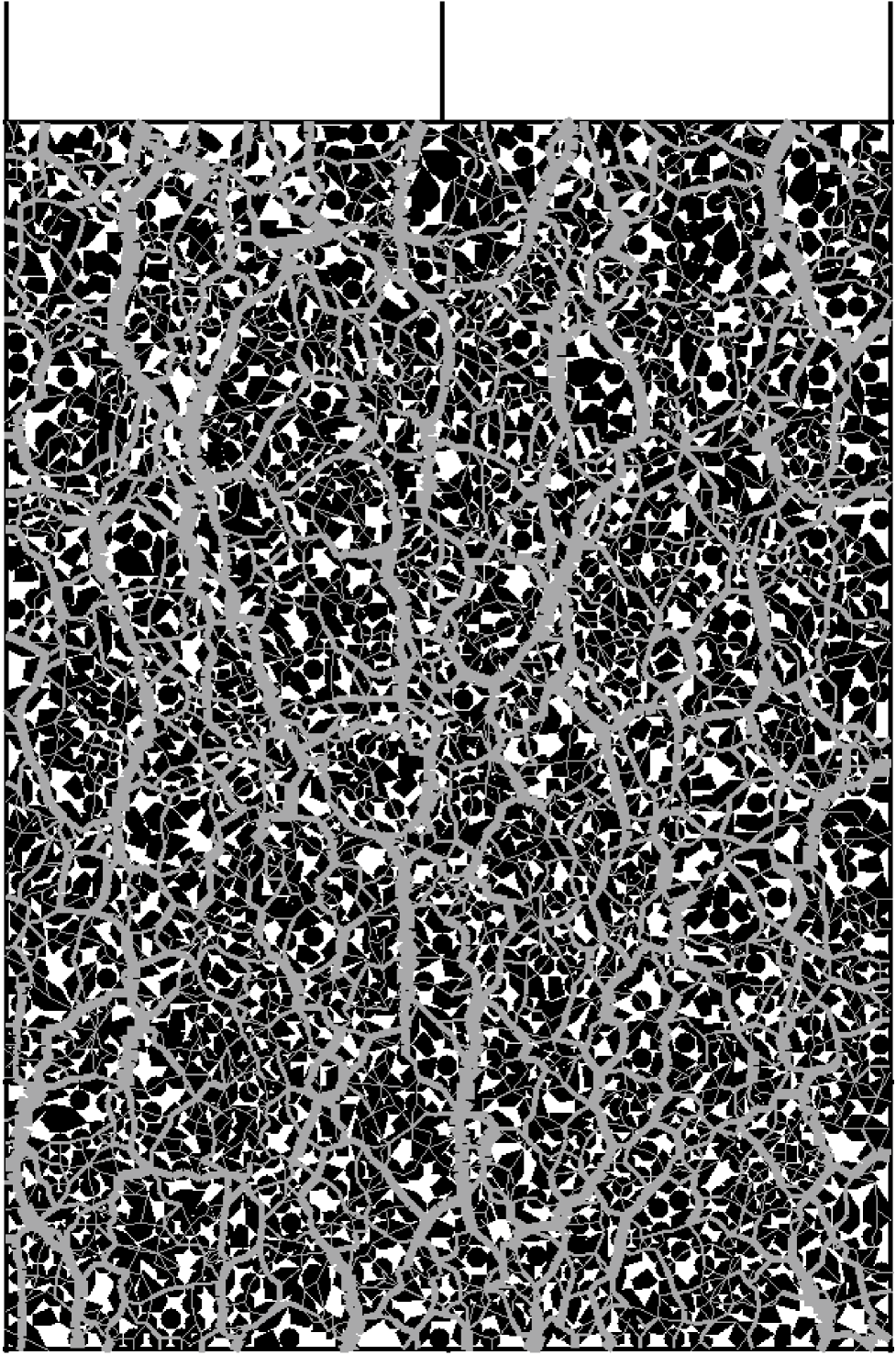
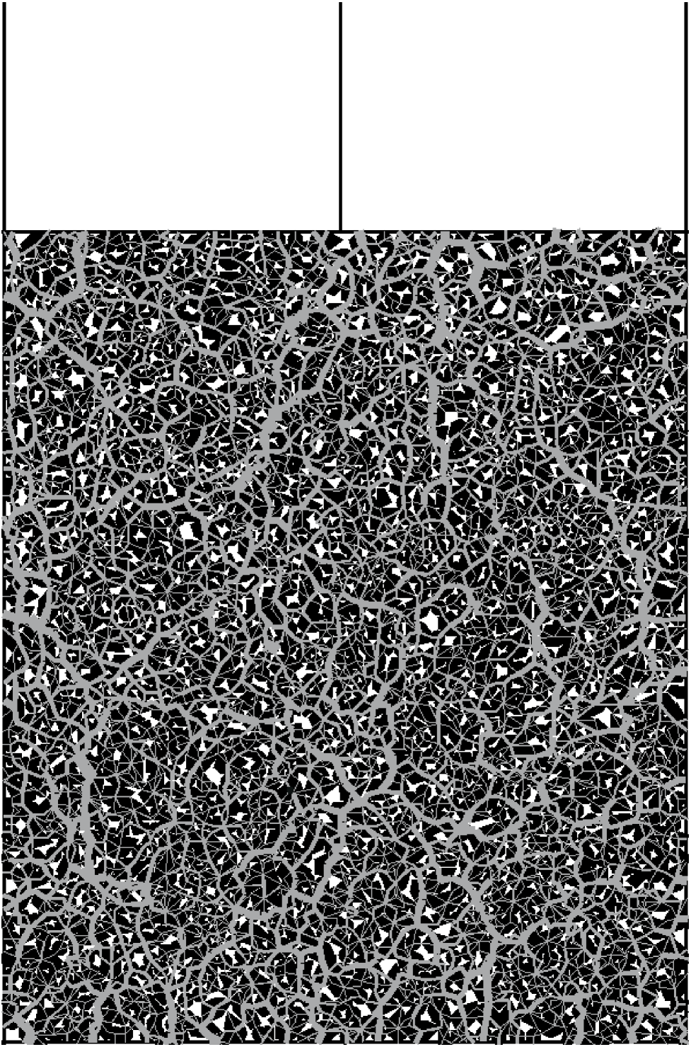
Initial configuration is a ballistic deposit with capture radius of particle radii (Fig. 5) containing particles. After the compaction process by applying an external force on the upper piston one finally reaches a final equilibrium state. Figure 7 shows the final state for different contact properties used within the simulation. If one uses Coulomb friction (C) only (in addition to excluded volume interaction) one ends up with a high volume fraction (78%). Using rolling friction in addition (CR) a volume fraction of 77% is reached. Compared to a perfect triangular lattice with volume fraction there are only a few larger pores in these two configurations. This can be explained by the fact that force chains must be stabilized by adjacent particles avoiding the lateral movement of the chains [23]. Coulomb friction and cohesion (CC) lead to larger pores (see Fig. 7) and thus a volume fraction of 68%. The stabilization mechanism of force chains (and thus pore stabilization) is a different one: Force chains of compressive forces (gray lines) are stabilized by nearby force chains of tensile forces (black lines) so that the piston load is carried by the system. The higher thickness of the force lines indicate that the stresses in the system are much higher than in the absence of cohesion. However, unhindered rolling leads to a destabilization of single particle chains. Therefore additional rolling friction (CRC) leads to the highest porosity (volume fraction of 51%) because the system includes stable single particle chains. In this case there is stabilization of three degrees of freedom: the separation of the particles, the lateral movement as well as the rolling against each other. These three degrees of freedom are stabilized by the combination of cohesion, Coulomb friction, and rolling friction.
C Compaction process

In order to get insight into the compaction process itself the temporal behaviour of the system is studied in this section. We simulated a ballistic deposit with capture radius containing monodisperse spherical particles (Fig. 8) with periodic boundary conditions in lateral direction. We compared the compaction dynamics for two different contact properties between the particles: coulomb friction (C) only leads to the most compact final configuration, whereas Columb, rolling friction and cohesion (CRC) lead to the most porous final configuration (see sec. III B). In both cases the time evolution of the piston position (Fig. 9) shows three phases of the compaction process. In the first phase the piston accelerates. Initially it is in contact with only one branch of the ballistic deposit. Only later it sweeps up substantial mass. Then, in the second phase the piston moves with a nearly constant velocity. The momentum transfered to the system by the force acting on the piston (in the cohesive case partly compensated by a reaction force of the opposite side of the container) is consumed by a linearly increasing mass swept up by the piston:
| (1) |
In the third phase the piston finally reaches a constant position (only neglectable small oscilations due to quasi-elasticity [4]): . The final position of the piston is different due to the different stabilization mechanism (see sec.III B).
D Influence of cohesion strength

The final piston position of different systems compactified by a constant external force is analyzed. At the contacts Coulomb and rolling friction, as well as cohesion with different values of are acting. The initial systems are ballistic deposits with capture radius and periodic boundary conditions. They consist of different numbers of particles and have different aspect ratios. We found that all the data collapse onto a single curve, Figure 10, if the final piston position is scaled by the final piston position without cohesion, , and the cohesive force by the pressure exerted by the piston, in the two dimensional case. In the beginning an (almost linear) increase can be seen. For large cohesive force the scaled final piston position reaches a constant value. In this region there is almost no compaction. The fact that is the relevant quantity for the compaction process implies that the typical distance of strong force lines is not depending on the system size, as is also found for systems without cohesion [23].
E Scaling behaviour for different initial densities

In the previous section the compaction of ballistic deposits with the same capture radius was investigated. Now three ballistic deposits of the same size in vertical and lateral directions, but different capture radius are compacted by a piston with a fixed external load. Thus the initial systems contain different numbers of spherical particles, namely (), () and particles (). The initial densities scale with (see fig. 6). The same plot as in figure 10 (each curve averaged over 10 runs) leads to a data collapse for small ratios of cohesion and external pressure on the piston only. In this region the different initial densities do not play an important role. For high cohesion values the final densities remain essentially the initial densities, so that there is no scaling in this region.
F Pore stabilization without cohesion
The results presented in Figs. 10 and 11 suggest the following physical picture: The external load of the piston must be carried by a set of strong force lines, which have a typical distance. The external load per force line is proportional to the pressure . It can be viewed as the destabilizing force along a force line and must be balanced by the stabilizing influence of another force, which in the previous sections was related to cohesion (and the fixed rolling friction), so that the scaling variable was . This variable had to be big enough to prevent compaction.
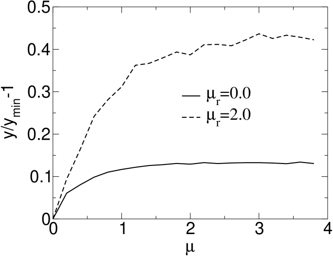
The question we want to address in this section is, whether friction forces alone can provide the stabilization as well. It is plausible to identify the external load per force line with the typical normal force at a contact along the force line, . The ratio between the stabilizing friction force and the destabilizing force would then be . This argument suggests that strong enough Coulomb friction may stabilize pores. This is indeed the case, as Fig. 13 shows. This effect is not very high (maximally about 10%), because the Coulomb friction cannot provide stabilization against buckling of the force lines. Therefore strong force lines need weak forces from the side as pointed out in [24]. Alternatively, rolling friction may stabilize the force lines against buckling. In combination with Coulomb friction this allows much larger pores, as the dashed curve in Fig. 13 shows. However, the pore geometry is totally different from the one obtained in cohesive materials (compare Figs. 8 and 12). In the absence of cohesion large pores are found underneath arches. Presumably strong force lines stop the motion of grains on the upper side, while below pores open up due to inertia effects. Cohesion would lead to correlated motion of clusters of grains and would also prevent the inertial rupture of the structure underneath an arch.
Without the use of rolling friction higher porosity will be reached by the use of non-sperical particles. To show this effect we simulated a a system of about particles consisting of two different convex polygonal particle types and one spherical particle type. The diameter of the particles is chosen within the same range. The initial configuration is a random loose packing, where no particles are in contact. After precompaction to a denser state the system is compacted by a piston with constant load using Coulomb friction coefficient (Fig. 14), respectively without Coulomb friction (Fig. 15). The two final configurations (Fig. 14, 15) have different porosity. It is higher, if Coulomb friction is present. Due to the shape disorder this effect is stronger than for the system of spherical particles. Here one ends up with a value compared to the value at for the ballistic deposits of monodisperse sperical particles (Fig. 12). One concludes that the corners of the particle have a similar effect as rolling friction for spherical particles.
Thus, for cohesive non-sperical grains one expects a higher porosity depending on the shape of the particles, due to a similar stabilization mechanism as we found for sperical particles using rolling friction.
IV Summary.
Different contact properties lead to different configurations after compaction. Using only Coulomb and rolling friction the final packing is an almost compact structure. The effect of cohesion on the porosity is higher if one uses Coulomb and rolling friction in addition. In that case single particle chains are stable and thus the packing is highly porous. Important is the strength of the cohesion: Low cohesive forces lead to similar packings as without cohesion. Important is the relation between the stabilizing (cohesion) and destabilizing (pushing force) forces. Here one has to take into account that forces are extremly inhomogeneously distributed in the system so that one must devide the external pushing force by the average distance between strong force lines. This picture is confirmed by applying it to a system with increased values for the friction coefficient (above ), which also leads to higher porosity.
V Acknowledgements
Useful conversations with T. Unger, M. Morgeneyer, J. Kertész J. Schwedes, Z. Farkás and H. Hinrichsen are gratefully acknowledged. We acknowledge support by DFG within SFB 445 Nano-Particles from the Gas-Phase: Formation, Structure, Properties and within the DFG grant WO 577/3-1 Compaction and Mechanical Properties of cohesive bulk solids.
REFERENCES
- [1] M. Morgeneyer and J. Schwedes. Macroscopic investigations on powder for calibration of microscopic models. to appear in WCPT4 Proceedings, 2002.
- [2] D.E. Wolf. Modelling and computer simulation of granular media. In K.H. Hoffmann and M. Schreiber, editors, Computational Physics: Selected Methods - Simple Exercises - Serious Applications, pages 64–94, Heidelberg, 1996. Springer.
- [3] G. Skandan, H. Hahn, B. H. Kear, M. Roddy, and W. H. Roddy. The effect of applied stress on densification of naostructured zirconia during sinter forging. Mat. Lett., 20:305, 1994.
- [4] T. Unger, L. Brendel, D. E. Wolf, and J. Kertész. Elastic behavior in contact dynamics of rigid particles. 2002. to be published in Phys. Rev. E, cond-mat/0203575.
- [5] M. Jean. The non-smooth contact dynamics method. Comput. Methods Appl. Engrg., 177:235–257, 1999.
- [6] J.J. Moreau. Some numerical methods in multibody dynamics: application to granular materials. Eur J Mech, A/Solids, 13(4):93–114, 1994.
- [7] G. A. D’Adetta, F. Kun, E. Ramm, and H. J. Herrmann. In Vermeer et al. [25], pages 231–258.
- [8] A. Schinner and H.-G. Mattutis. Molecular dynamics of cohesive granular materials. In D. Helbing, H.-J. Herrmann, M. Schreckenberg, and D. E. Wolf, editors, Traffic and Granular Flow ’99, pages 505–510, Berlin, 2000. Springer.
- [9] S. Roux. Quasi-static contacts. NATO ASI Series, Series E: Applied Sciences - Vol. 350, pages 267–284, Dordrecht, 1998. Kluwer Acad. Publ. Proceedings (Conference 1997).
- [10] S. Luding. From microscopicsimulations to macroscopic material behavior. Comp. Phys. Comm., 2002. in press.
- [11] F. Radjai, I. Preechawuttipong, and R. Peyroux. In Vermeer et al. [25], pages 149–162.
- [12] M. Jean, V. Acary, and Y. Monerie. Non-smooth contact dynamics approach of cohesive materials. Phil. Trans. R. Soc. Lond. A, 359:2497–2518, 2001.
- [13] D. Kadau, G. Bartels, L. Brendel, and D. E. Wolf. Contact dynamics simulations of compacting cohesive granular systems. Comp. Phys. Comm., 2002. in press.
- [14] T. Travers, D. Bideau, A. Gervois, and J. P. Troadec. Uniaxial compression effects of 2d mixtures of ’hard’ and ’soft’ cylinders. J. Phys. A: Math. Gen., 19:L1033, 1986.
- [15] G. Bartels, Z. Farkás, D. Kadau, T. Unger, J. Kertész, and D. E. Wolf. in preparation.
- [16] M. Jean and J. J. Moreau. Unilaterality and dry friction in the dynamics of rigid body collections. In Proceedings of Contact Mechanics International Symposium, pages 31–48, Lausanne, Switzerland, 1992. Presses Polytechniques et Universitaires Romandes.
- [17] F. Radjai, L. Brendel, and S. Roux. Nonsmoothness, indeterminacy, and friction in two-dimensional arrays of rigid particles. Phys. Rev. E, 54(1):861–873, 1996.
- [18] Y. C. Zhou, B. D. Wright, R. Y. Yang, B. H. Xu, and A. B. Yu. Rolling friction in the dynamic simulation of sandpile formation. Physica A, 269:536–553, 1999.
- [19] N. V. Brilliantov and T. Pöschel. Rolling friction of a viscous sphere on a hard plane. Europhys. Lett., 42(5):511–516, 1998.
- [20] M. Krafczyk, P. Lehmann, O. Filippova, D. Hänel, and U. Lantermann. Lattice boltzmann simulations of complex multiphase flows. In Multifield Problems, pages 50–57, Berlin, 2000. Springer.
- [21] O. Filippova and D. Hänel. Lattice boltzmann simulations of gas-particle flow in filters. Comp. and Fluids, 26(7):697–712, 1997.
- [22] P. Meakin and R. Jullien. Ballistic deposition with sticky and non-sticky particles. Physica A, 175(2):211–221, 1991.
- [23] Farhang Radjai and Dietrich E. Wolf. Features of static pressure in dense granular media. In Granular Matter, volume 1, pages 3–8, 1998.
- [24] Farhang Radjai, Dietrich E. Wolf, Michel Jean, and Jean Jacques Moreau. Bimodal Character of Stress Transmission in Granular Packings. Phys. Rev. Lett., 80:61, 1998.
- [25] P. A. Vermeer, S. Diebels, W. Ehlers, and H. J. Herrmann, editors. Continuous Modelling of Cohesive-Frictional Materials. Springer, 2001.