Dynamics of a single vortex line in a Bose-Einstein condensate
Abstract
We study experimentally the line of a single quantized vortex in a rotating prolate Bose-Einstein condensate confined by a harmonic potential. In agreement with predictions, we find that the vortex line is in most cases curved at the ends. We monitor the vortex line leaving the condensate. Its length is measured as a function of time and temperature. For a low temperature, the survival time can be as large as 10 seconds. The length of the line and its deviation from the center of the trap are related to the angular momentum per particle along the condensate axis.
pacs:
03.75.Fi,32.80.Pj,67.40.VsThe macroscopic motions of quantum and classical fluids are dramatically different. The description of a quantum fluid by a macroscopic wave function imposes strong constraints upon its velocity field. At a position of non-vanishing density , the velocity is related to the phase by , where is the mass of a particle of the fluid. Hence . A rotational motion of the fluid can be obtained only through the nucleation of vortex lines, along which the density is zero and around which the circulation of the velocity is quantized in units of Onsager ; Feynman .
Quantized vortices play an essential role in the dynamics of all quantum macroscopic objects. Examples are flux lines in superconductors Tinkham , and vortex lines in superfluid liquid helium Donnelly91 and gaseous Bose-Einstein condensates (BEC) Cornellphaseimprinting ; Madison00 ; Cornellcooling ; Ketterle ; Hodby01 . Among the remaining problems, is the shape of a vortex/flux line and the study of its time evolution. The observation of inclined flux lines in superconductors was only possible due to recent advances in electron microscopy fluxlineMFM . In gaseous BEC, one has comparably easy access to the vortex line because the density of the atom cloud is low. A few disordered vortex lines have been observed by taking tomographic images perpendicular to the long axis of a cigar shaped condensate Ketterle . An array of many vortex lines in a pancake shaped condensate has been observed by transverse imaging of the whole atom cloud Engels02 .
In this Letter we report the full length observation of a single vortex line in a cigar shaped condensate. We find that as a result of spontaneous symmetry breaking the line is generally bent. Our experimental results confirm recent predictions, in which the shape of the vortex line minimizing the energy of the gas was derived for a given rotation frequency Garcia01a ; Garcia01b ; Aftalion01 ; Modugno ; Aftalion02 . We also study the time evolution of the shape of the line. As the angular momentum of the gas slowly decays, the bending of the vortex line and its deviation from to the center of the trap increase. We investigate the influence of temperature on these dynamics. From our results one can hope to draw some indications for the shape and dynamics of the vortex/flux line in systems where a direct observation is not yet possible.
Our 87Rb condensate is formed by radio-frequency (rf) evaporation of atoms in a Ioffe-Pritchard magnetic trap. The atoms are spin-polarized in the state. The magnetic trap has a longitudinal frequency Hz and a transverse frequency Hz (the axis is vertical). Because gravity slightly displaces the center of the trap with respect to the magnetic field minimum, the potential in the plane is not perfectly isotropic and we measure a 1% relative difference between and .
The initial temperature of the cloud, which is pre-cooled using optical molasses, is 100 K. The condensation threshold is reached at nK, with atoms. We cool to typically nK which corresponds to a condensate with atoms and a chemical potential nK. It is obtained using kHz as the final rf, where is the frequency at which the trap is emptied. During the rest of the experimental cycle, we maintain the evaporation rf at an adjustable level, typically kHz. This allows us to control the temperature while observing the vortex line.
Once the condensate is formed, we use an off-resonant laser beam to impose on the trapping potential an elliptic anisotropy in the plane Madison00 . The wavelength of the beam is 852 nm, its power 0.1 mW and its waist m. Acousto-optic modulators deflect the position of the beam in the plane, thereby rotating the potential anisotropy at a frequency of Hz. We apply this “laser stirrer” for 300 ms, during which 7 or more vortices are nucleated Madison01 . After the stirring phase, the condensate evolves freely in the magnetic trap for an adjustable time .
The preparation of a single vortex line takes advantage of the slight static anisotropy of our magnetic trap, so that the angular momentum is not exactly a constant of motion. In a time – s, we observe a transition from a multi-vortex condensate to a condensate with a single vortex. This relatively long time levels the fluctuations that may occur during the nucleation process. Thereby we are able to reproduce a single vortex condensate on every experimental cycle. This vortex line can then be studied for a time s.
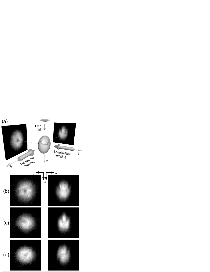
The atom distribution at is probed (destructively) by switching off the magnetic trap, letting the cloud expand during ms and performing absorption imaging. Two imaging beams aligned along the and directions probe the atom cloud simultaneously (Fig. 1a). The beams are combined onto a camera with the same magnification. During the expansion, the transverse dimensions and of the condensate are magnified by , while the longitudinal dimension is nearly unchanged Castin96 . It has been shown theoretically that the presence of a single vortex line does not alter this expansion and that the coordinates of the line are scaled by the same factors Modugno .
Figs. 1 b-d show three condensates imaged after various times. The left column shows the “longitudinal” view along , representing the atom distribution in the plane. The right column depicts the “transverse” view taken along the direction, representing the atom distribution in the plane. The vertical () direction is identical for all images. The transverse images show the typical atom distribution where the ellipticity is inverted with respect to the in situ cigar form, caused by the transverse expansion during .
As in Madison00 , we use the longitudinal images in Fig. 1 to verify the presence of a single vortex. The transverse image in Fig. 1b obtained for s shows the vortex line as a line of lower atom density. Clearly this vortex line is not straight. It rather has the shape of a wide “U”. The position of the axial part of the vortex line (bottom of the U) is close to the center of the condensate. It coincides with the position of the dip in density seen in the longitudinal image. In the laboratory frame, the curved vortex line is expected to rotate around the axis with a frequency related to the angular momentum of the condensate. This is confirmed by the fact that we observe up- and downwards bending with equal probability.
Fig. 1c shows images taken after s, for which the angular momentum has decreased significantly compared to Fig. 1b. In the longitudinal view, one sees a vortex off-center and in the transverse view a narrow U, where the bottom of the U no longer extends to the center of the condensate.
Fig. 1d shows a vortex line in the shape of an unfolded “N”, observed after s. The width of the N, which is the projection of the vortex line onto the axis, is comparable to the width of the U in Fig. 1b. The fact that U as well as N shaped vortex lines are observed leads to the question whether the bending occurs in one plane or whether three dimensional deformations of the vortex line can also occur. We have indications that this may be the case: some transverse views (not shown here) reveal asymmetric U or N shaped vortex lines.
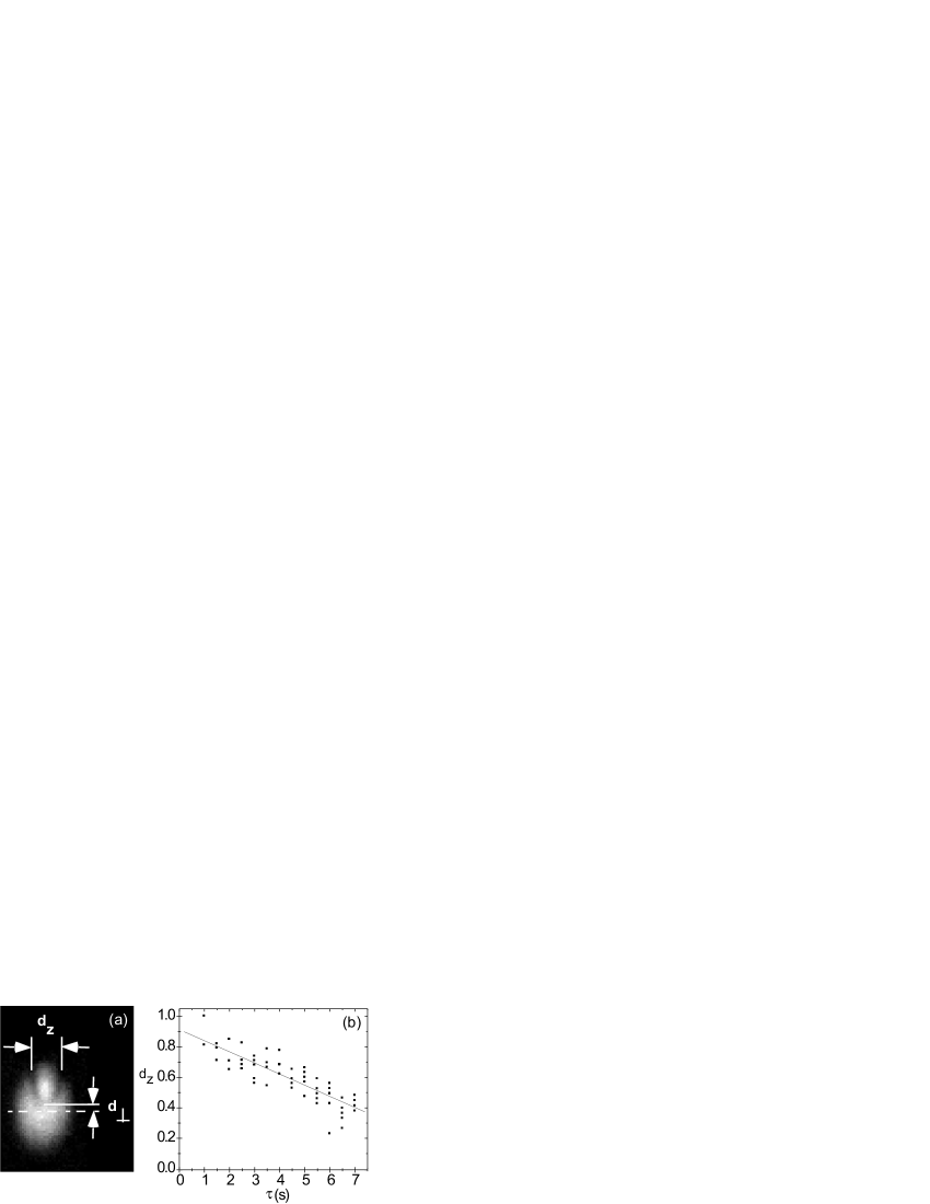
In order to give a quantitative analysis, we measure by hand the distance along the direction between the two points where the vortex line leaves the condensate (Fig. 2a). We do not distinguish U and N shaped vortices. Normalization by the length of the condensate along leads to the quantity . In Fig. 2b, we plot as a function of . Each point in the plot corresponds to a single image. The small spread of the points demonstrates the reproducibility of the vortex shape. The normalized length of the vortex line decreases quasi-linearly with time.
Fig. 2b shows that after s the vortex is still present. This differs from our earlier reports Madison00 simply because we have used two different methods of identifying the vortex. In Madison00 only the longitudinal view was available. Now we find that a vortex can still be identified in the transverse view, while in the longitudinal image the density variation due to the bent vortex line is within the background fluctuations. This long lifetime can be compared with the MIT result Ketterle , where a vortex array with more than 100 vortices was produced at . The number of vortices was divided by in s; however a single vortex could still be detected after s. In both experiments, it is clear that the decay time of the last vortex is much longer than the decay time of the initial vortex lattice.
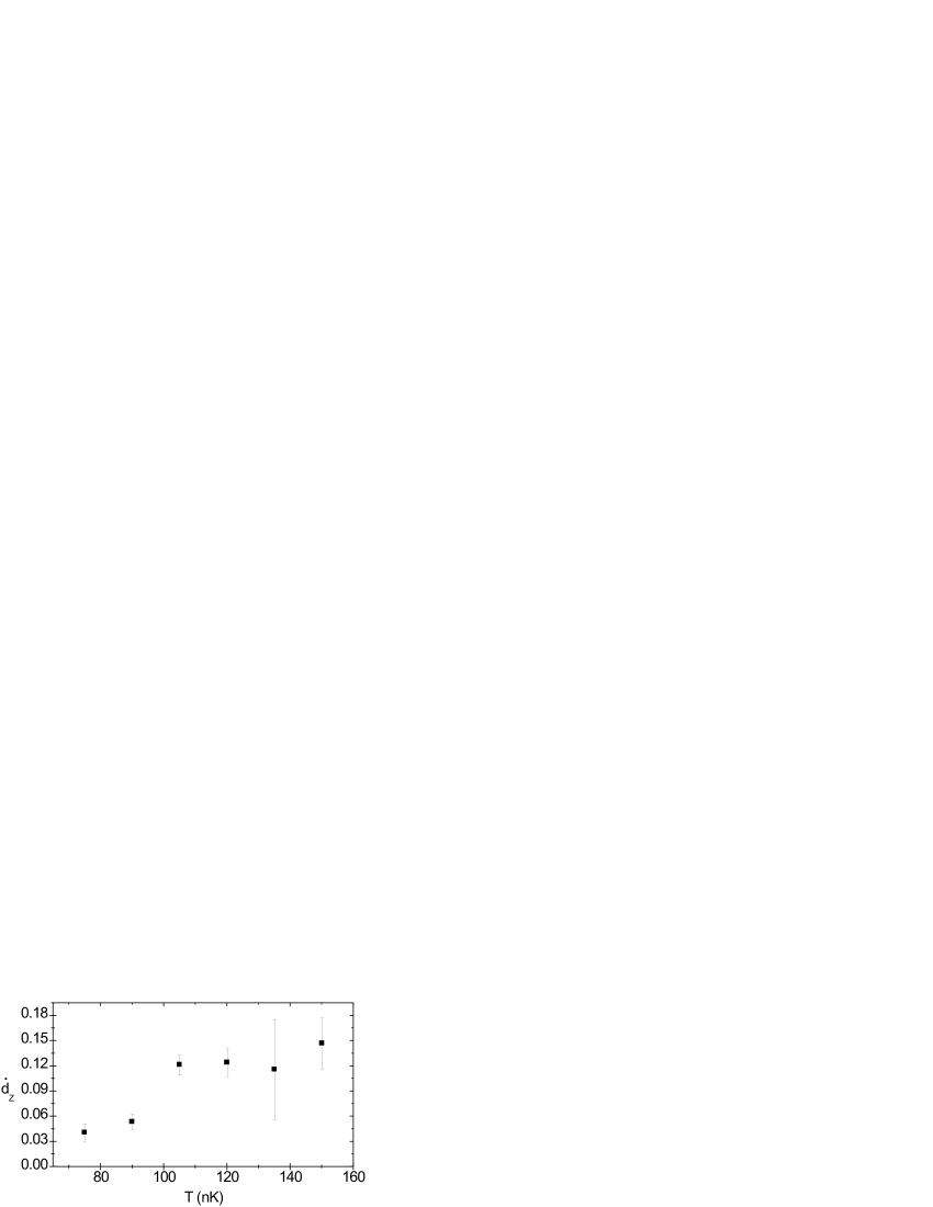
We have repeated the experiment of Fig. 2 for different evaporation radiofrequencies (implying different temperatures ) during the free evolution time . We always observe a quasi-linear decrease of and fit its slope, . It is plotted in Fig. 3 as a function of . Clearly the longest vortex lifetime is obtained for small temperatures, confirming the idea that the vortex line is dragged to the edge of the condensate by a thermally activated process Fedichev . Note that at the lowest temperature we observe almost exclusively U shaped vortices, while U and N are equally probable at the second lowest temperature.
In a last experiment we vary again in order to prepare condensates with various lengths of the vortex line. We measure the angular momentum per particle by the same method as in lz . The presence of a vortex leads to the lift of degeneracy between the two quadrupole surface modes carrying angular momentum Stringari : , where is the radius in the transverse plane. We excite a superposition of these two modes by a 1.9 ms flash of our laser stirrer and we probe the quadrupole oscillation at ms and ms after the flash. We repeat the experiment a third time without the laser flash and analyze the shape of the vortex line. As above we extract the normalized length of the vortex line along the axis. We also measure the displacement of the axial part of the vortex line (bottom of the U) from the center of the condensate, and normalize it by the radius of the condensate in the plane (Fig. 2a). Since we have access only to the projection of the decentering on the plane, we actually measure , where is the azimuthal angle of the axial part of the line. We account for this geometrical factor by dividing the measured displacement by .
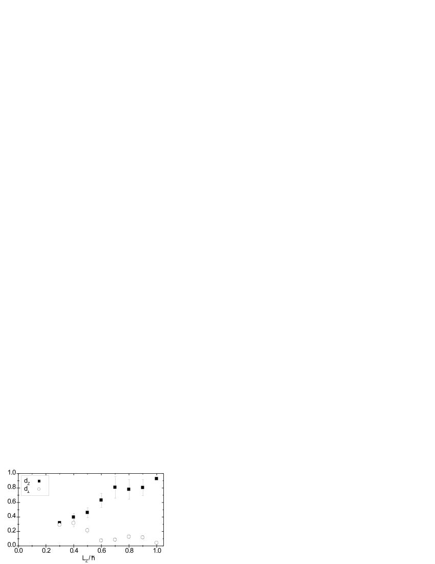
Fig. 4 shows and as functions of . For clarity we group all points into bins of and average over and . The error bars give the statistical variation. The data corresponding to are not reproducible enough and are omitted. The graph shows that and are approximately equal. A straight () and well centered () vortex line corresponds to an angular momentum of the order of . When the angular momentum decreases, we measure a decentering as long as . Below , rises to 0.3.
We now compare our experimental results with recent predictions for the shape of a vortex line in an inhomogeneous cigar shaped condensate Garcia01a ; Garcia01b ; Aftalion01 ; Modugno ; Aftalion02 . These theoretical studies consist in looking for the ground state of the condensate in a frame rotating at an angular frequency . The general conclusion is that above a critical frequency the ground state of the system has one or several vortices. The central vortex is generally bent if the trap aspect ratio is large compared to 1, which is the case in our experiment. A simple physical picture of the bending is given in Modugno . A cigar shaped condensate can be viewed as a series of 2D sheets of condensate at various . For each sheet, one has a 2D vortex problem leading to a critical frequency above which a centered vortex is the stable solution. For a given rotation frequency , it can happen that a centered vortex is the minimal energy configuration for the sheets close to (i.e. ), while it is not the case for the sheets close to the edges of the condensate where the atom density is lower. In this case, the vortex line minimizing the total energy is well centered for , and is strongly bent for , where . A precursor of this bending effect can also been found in Svidzinsky ; Feder in which a stability analysis of a straight vortex in an elongated condensate showed that some bending modes have negative energy, and are thus unstable.
Our experimental procedure is somewhat different from the one considered in these theoretical studies. In our case no rotating anisotropy is imposed onto the condensate during the relevant evolution. The stirring laser has been switched on for a short time only, at the beginning of the procedure, in order to set a non-zero angular momentum in the system. We observe the evolution of the condensate in our static trap, as the angular momentum of the gas slowly decays. However, the shape of the vortex line that we observe at short time in Fig. 1b is remarkably similar to those predicted and plotted in Garcia01a ; Garcia01b ; Aftalion01 ; Modugno . As pointed out in Garcia01b , this bending is a symmetry breaking effect which does not depend on the presence of a rotating anisotropy and which happens even in a completely symmetric setup anisotropy . A decentered single vortex similar to the one shown in Fig. 1c was also found as the ground state of the rotating system in Aftalion01 for a given rotation range. By contrast, we did not find in the literature predictions for N-shaped vortices, such as the one shown in Fig. 1d. This probably means that a N-shaped vortex is slightly more energetic than a U shaped vortex with the same angular momentum, and that it could not emerge from a procedure aiming to find the ground state of the system.
Our results also provide information on the dynamics of the vortex line and the way it escapes from the condensate. A theoretical model has been proposed, in which the decay is due to the coupling with the non-rotating thermal component Fedichev . In this model, the authors considered a spatially homogenous condensate in a cylindrical vessel. The vortex line, assumed to be straight, spirals out of the condensate. The bending of the line that we observe experimentally may change qualitatively the picture, since we find that the decay occurs first by an increased bending and, only in a second step, by a deviation of the center of the line (bottom of the U) from the center of the condensate.
In conclusion we have reported the observation of the full line of a single quantized vortex. We have related its shape (bending and deviation from center) to the angular momentum of the system. Our results should help modelling the dissipative evolution of a rotating Bose-Einstein condensate.
Acknowledgements.
We thank Y. Castin, F. Chevy and G. Shlyapnikov for useful discussions. P. R. acknowledges support by the EC (contract number HPMF CT 2000 00830). This work was partially supported by CNRS, Collège de France, Région Ile de France, DGA, DRED and EC (TMR network ERB FMRX-CT96-0002).References
- (1) Unité de Recherche de l’Ecole normale supérieure et de l’Université Pierre et Marie Curie, associée au CNRS.
- (2) L. Onsager, Nuovo Cimento 6, suppl. 2, 249 (1949).
- (3) R.P. Feynman, in Progress in Low Temperature Physics, vol. 1, Chapter 2, C.J. Gorter Ed. (North-Holland, Amsterdam, 1955).
- (4) M. Tinkham, Introduction to superconductivity (McGraw-Hill, 1996).
- (5) R.J. Donnelly, Quantized Vortices in Helium II, (Cambridge, 1991).
- (6) M.R. Matthews et al., Phys. Rev. Lett. 83, 2498 (1999).
- (7) K.W. Madison et al., Phys. Rev. Lett. 84, 806, (2000).
- (8) J.R. Abo-Shaeer et al., Science 292, 476 (2001); C. Raman et al., Phys. Rev. Lett. 87, 210402 (2001).
- (9) E. Hodby et al., Phys. Rev. Lett. 86, 2196 (2001).
- (10) P.C. Haljan et al., Phys. Rev. Lett. 87, 210403 (2001).
- (11) A. Tonomura et al., Nature 412, 620 (2001); A. Tonomura et al., Phys. Rev. Lett. 88, 237001 (2002).
- (12) P. Engels et al., cond-mat/0204449.
- (13) J.J. García-Ripoll and V.M. Pérez-García, Phys. Rev. A 63, 041603 (2001).
- (14) J.J. García-Ripoll and V.M. Pérez-García, Phys. Rev. A 64, 053611 (2001).
- (15) A. Aftalion and T. Riviere, Phys. Rev. A 64, 043611 (2001).
- (16) M. Modugno et al., cond-mat/02033597.
- (17) A. Aftalion and R. L. Jerrard, cond-mat/0204475.
- (18) K.W. Madison et al., Phys. Rev. Lett. 86, 4443 (2001).
- (19) Y. Castin and R. Dum, Phys. Rev. Lett. 77, 5315 (1996).
- (20) P.O. Fedichev and G.V. Shlyapnikov, Phys. Rev. A 60, R1779 (1999).
- (21) F. Chevy et al., Phys. Rev. Lett. 85, 2223 (2000).
- (22) F. Zambelli and S. Strigari, Phys. Rev. Lett. 81, 1754 (1998).
- (23) A.A. Svidzinsky and A.L. Fetter, Phys. Rev. A 62, 063617 (2000).
- (24) D.L. Feder et al., Phys. Rev. Lett. 86, 564 (2001).
- (25) The small static anisotropy of our trap should not influence the symmetry breaking which occurs in the rotating frame.