Permanent address: ]Department of Physics and Informatics, University of São Paulo at São Carlos, 13560-970 São Carlos/SP, Brazil.
Rashba spin-orbit interaction and shot noise for spin-polarized and entangled electrons
Abstract
We study shot noise for spin-polarized currents and entangled electron pairs in a four-probe (beam splitter) geometry with a local Rashba spin-orbit (s-o) interaction in the incoming leads. Within the scattering formalism we find that shot noise exhibits Rashba-induced oscillations with continuous bunching and antibunching. We show that entangled states and triplet states can be identified via their Rashba phase in noise measurements. For two-channel leads we find an additional spin rotation due to s-o induced interband coupling which enhances spin control. We show that the s-o interaction determines the Fano factor which provides a direct way to measure the Rashba coupling constant via noise.
pacs:
71.70.Ej,72.70.+m,72.25.-b,73.23.-b,72.15.GdSpin-related effects in transport form the basis of the emerging field of semiconductor spintronics springer . Moreover, the electric control of intrinsic magnetic degrees of freedom offers an important mechanism to manipulate and probe spin transport. For instance, the spin-transistor proposal of Datta and Das datta highlights the relevance of a gate-controlled Rashba spin-orbit interaction as a means of spin rotating electron states in one-dimensional channels.
In this work, we investigate the transport properties of spin-polarized spin-pol ; egues and spin-entangled entangler ; BLS electrons for a beam-splitter configuration liu ; oliver ; henny with a local Rashba spin-orbit (s-o) interaction, which acts within a finite region (length ) of the incoming leads, see Fig. 1 (left). Due to such a local s-o term the spinors of the incoming electrons can be varied continuously, which affects then the orbital symmetry of the wave function (via the Pauli principle) and thus transport properties such as current and noise. Within the scattering approach buttiker we calculate current noise for leads with one and with two channels, see Fig. 1 (right). We find that shot noise for spin-polarized and entangled electrons strongly oscillates as a function of the Rashba coupling and the length . In particular, singlet (triplet) pairs exhibit intermediate degrees of (anti-)bunching behavior BLS ; taddei . We show that entangled pairs as well as triplet states can be identified in noise experiments via their Rashba phase. We find that the s-o interaction determines the Fano factor, implying that the Rashba coupling can be measured via noise. Finally, we find an additional spin phase due to s-o induced interband coupling for leads with two channels. Since this modulation can be varied via the lateral confinement of the lead, this effect provides a new mechanism for electrical spin control.
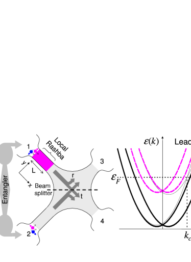
System. We consider an experimentally feasible beam-splitter geometry liu ; oliver ; henny with two incoming and two outgoing leads, Fig. 1. We assume that the local Rashba coupling in this lead can be externally controlled via a proper gating structure nitta ; grundler . The injected electrons (entangled or not) undergo a local spin evolution within an extension in lead 1. Note that we do not consider a Rashba interaction in lead 2; we are interested only in phase differences between leads 1 and 2. However, it is straightforward to extend our analysis to include s-o interaction in both incoming leads. We consider first single-channel leads (one occupied band), and then move on to the more involved case of two channels. For an incoming plane wave with wave vector k along the x direction the Rashba term is simply rashba ; molenkamp , where denotes the s-o coupling constant.
Spin transfer operator. The rotation of the spin state can be described by a unitary transfer operator. This unitary operator can then be incorporated straightforwardly into the usual scattering matrix (Landauer-Büttiker) formalism for coherent transport buttiker in order to calculate the current and the current correlators. We find that the transfer operator through the Rashba region is , i.e., a rotation about the axis by an angle , denotes the electron effective mass. This Rashba rotation is well known datta and occurs only for incoming electrons having a spin component perpendicular to . In the basis of the eigenstates of , we can write
| (1) |
For instance, an incoming plane wave in lead 1 with spin up, , emerges at the other side of the Rashba region in the rotated state dynamical
| (2) |
In the above we assume a unity transmission probability for electrons through the Rashba region. Indeed, since there is no additional band offset due to different materials in our incoming lead mismatch . This implies that the Rashba interaction does not directly introduce noise in the lead – it simply rotates the incoming spin state. However, indirectly it does affect the noise characteristic of the entire system since it effectively changes the beam-splitter scattering matrix, as we shall see next.
Scattering approach. After leaving the Rashba region of length within lead 1 an electron is left in a linear superposition of spin-up and spin-down states with a phase , Eq. (2). Both components of this superposition freely and independently move into the beam-splitter region where we assume they are partially transmitted to lead 3 or 4 . We can now combine the scattering matrices for the transmission of electrons through the Rashba region and for the spin-independent scattering of electrons from the incoming lead to the outgoing lead at the beam splitter . The combined scattering matrices and describe both the Rashba evolution within lead 1 and the subsequent transmission into leads 3 and 4. Here, and denote the reflection and transmission amplitudes at the beamsplitter, respectively. Electrons from lead 2 are similarly transmitted into lead 3 or 4, but with no Rashba rotation. Here we have and . Hence we define the total scattering matrix
| (3) |
relevant for calculating transport properties.
Shot noise. Shot noise blanter is a non-equilibrium current fluctuation arising from the discrete nature of the charge flow (at zero temperature). At a time , the current fluctuation about its average in lead is . As usual, shot noise is defined as the Fourier transform of the symmetrized current-current autocorrelation function between leads and
| (4) |
The current in lead in the scattering approach buttiker is
| (5) | |||||
where , and denotes the creation (annihilation) fermionic operator for an electron with energy in lead ; is the spin component along a proper quantization direction (). The spin-dependent s matrix is defined in Eq. (3). Below we determine explicit formulas for spin-polarized and spin-entangled electrons.
Spin-polarized electrons. For Fermi liquid leads we obtain the well-known noise formula buttiker – but with a spin-dependent s matrix – after performing the ensemble average in Eq. (4). For spin-polarized electrons and a small bias applied between the incoming (1,2) and outgoing (3,4) leads we find to linear order in and at zero temperature
| (6) |
where is the beam-splitter transmission, the degree of spin polarization in leads 1 and 2, and the mean current in lead 3.
Spin-entangled electrons. For electron pairs, the average in Eq. (4) is a quantum mechanical expectation value between two-electron states. We consider the following injected states delay in leads 1 and 2
| (9) | |||||
| (10) |
where denotes the ground state (filled or not) Fermi sea of the leads. The states and are the entangled singlet and triplets, respectively, while are unentangled triplets. Here we have in mind an entangler entangler attached to leads 1 and 2, Fig. 1. We assume that these pairs have discrete energies above BLS .
At zero temperature and applied voltage and , the Fermi sea is completely inert and the noise in the system is solely due to the injected pairs above the Fermi surface BLS . For the singlet and triplets in Eq. (10) and the s matrix in Eq. (3), we find formula
| (11) |
where the factor , , , , , depends on the Rashba phase . The density of states in (11) arises because of the discrete levels. For the spin singlet
| (12) |
where are denote the discrete energies of the paired electrons. For the triplet states in and directions
| (13) | |||||
| (14) | |||||
| (15) |
Two channels and s-o interband coupling. So far we have considered a strictly 1D lead with a local Rashba interaction. Now we consider the case in which lead 1 has two transverse Rashba channels and moroz . We assume a weak s-o interband coupling which splits the bands near the crossing point , Fig. 1 (right). To lowest order this splitting is , .
After traversing the Rashba region, a spin up (down) electron impinging at the band crossing is left in the state
| (18) | |||
| (21) |
where formula . To obtain (21) we have expanded an incoming spin-up (down, ) state in channel a in terms of the s-o interband-coupled states near the energy crossing at , see Fig. 1. We describe these interband-coupled states perturbatively in analogy to the standard nearly-free electron model. Incoming electrons are now injected into linear combinations of unperturbed states (of channels a and b) near which satisfy proper boundary conditions for the velocity operator molenkamp .
Equation (21) clearly shows that impinging electrons with energies near the band crossing undergo further spin rotation . This extra modulation arises because of channel mixing due to Rashba interband coupling. For , Eq. (21) yields the state (2) with a single rotation . An estimate of is readily obtained for infinite transverse confinement: assuming an energy (at the crossing) and ; hence ( for nm and eVm nitta ; grundler ; for this the lateral width of the channel is nm). Therefore even a “weak” interband coupling yields a sizable additional rotation . This spin rotation for electrons injected at the band crossing produces an additional modulation of the transport properties. In particular, we find formula for the spin-resolved charge current in lead 1
| (22) |
which clearly shows the additional modulation hausler .
Generalized Fano factors. To determine shot noise in the presence of s-o interband coupling we proceed as before with the following extensions. For electron pairs, for instance, we consider the states in Eq. (10); here, however, the electron pair component in lead 1 evolves according to (21). After a somewhat lengthy calculation formula , we find that the Fano factors for the noise are now functions of both the Rashba angle and the interband mixing angle ,
| (23) | |||||
| (24) | |||||
| (25) | |||||
| (26) |
The above equations reduce to the 1D case [Eqs. (6) and (12)–(15)] for .
Discussion. Figure 2 displays the “normalized” Fano factor , , as a function of the Rashba phase for the (a) spin-polarized case [Eq. (6) with , here ], (b) injected singlet and triplet pairs [Eqs. (12)–(15), here ]. In Fig. 2 we plot for two quantization directions: and ( is equivalent to ), where “” defines the Rashba rotation axis. In Fig. 2(a) only -polarized electrons in leads 1 and 2 generate noise as is varied; -polarized electrons are not affected by the Rashba rotation about .
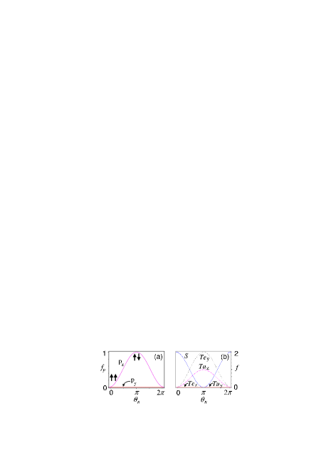
Because of the distinct symmetry of the orbital part of the pair wave function, shot noise for singlet and triplet states is not the same. As detailed in Ref. BLS singlet pairs have a symmetric orbital wave function thus showing “bunching” behavior; triplets, on the other hand, show “antibunching” since their orbital wave function is antisymmetric. The Rashba phase modifies the symmetry of the spin part of the pair wavefunction; hence intermediate degrees of bunching or antibunching can be induced.
Figure 2(b) shows that shot noise for entangled singlet and triplet states display oscillatory bunching/antibunching behavior as a function of the Rashba phase (singlet and triplets differ by ). Via these oscillations it is possible to distinguish the entangled triplet states or from the respective unentangled ones or . For the difference in noise vanishes, i.e., BLS .
Moreover, the oscillations in Fig. 2 suggest a direct way to obtain the s-o coupling constant via measuring shot noise; for instance, from Eq. (6) () we find
| (27) |
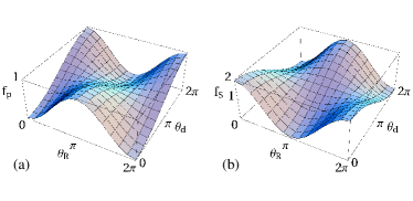
Figure 3 illustrates the effect of the additional spin-rotation (interband coupling) on the normalized Fano factor f; only the spin-polarized and the singlet cases are shown. This extra rotation can lead to a complete reversal of bunching/antibunching behavior for electrons near the band crossing [see Fig. 1 (right)]. Hence additional spin control is attained by varying the s-o interband coupling through the lateral width of the confining potential (e.g., via side gates).
Conclusion. Rashba s-o (interband) coupling strongly modulates current and shot noise for spin-polarized and entangled electrons in a beam-splitter geometry. This provides a means of probing spin properties in charge transport and offers a direct way to measure s-o coupling constants.
This work was supported by NCCR Nanoscience, the Swiss NSF, DARPA, and ARO. We acknowledge useful discussions with C. Schroll, H. Gassmann, and D. Saraga.
References
- (1) Semiconductor Spintronics and Quantum Computation, eds. D. D. Awschalom, D. Loss, and N. Samarth (Springer, Berlin, 2002).
- (2) S. Datta and B. Das, Appl. Phys. Lett. 56, 665 (1990).
- (3) R. Fiederling et al., Nature 402, 787 (1999); Y. Ohno et al., Nature 402, 790 (1999).
- (4) J. C. Egues, Phys. Rev. Lett. 80, 4578 (1998).
- (5) P. Recher et al., Phys. Rev. B 64, 165314 (2001).
- (6) G. Burkard et al., Phys. Rev. B 61, R16303 (2000).
- (7) R. C. Liu et al., Nature (London), 391, 263 (1998).
- (8) W. D. Oliver et al., in Quantum Mesoscopic Phenomena and Mesoscopic Devices in Microelectronics, vol. 559 of NATO ASI Series C: Mathematical and Physical Sciences, eds. I. O. Kulik and R. Ellialtioglu (Kluwer, Dordrecht, 2000), pp. 457-466.
- (9) M. Henny et al., Science 284, 296 (1999).
- (10) M. Büttiker, Phys. Rev. B 46, 12485 (1992); See G. Feve et al. (cond-mat/0108021) for a description of the scattering formalism using Rashba states (single-moded leads).
- (11) F. Taddei and R. Fazio, Phys. Rev. B 65, 075317 (2002).
- (12) J. Nitta et al., Phys. Rev. Lett. 78, 1335 (1997).
- (13) D. Grundler, Phys. Rev. Lett. 84, 6074 (2000).
- (14) Yu. A. Bychkov and E. I. Rashba, JETP Lett. 39, 78 (1984).
- (15) L. W. Molenkamp et al., Phys. Rev. B 64, R121202 (2001); M. H. Larsen et al., ibid. 66, 033304 (2002).
- (16) We can view the Rashba rotation (1) as a time evolution , within the electron traversal time () across the Rashba region.
- (17) A very small mismatch arises because in the Rashba region. To lowest order in the s-o coupling we find , where is the reflection amplitude (single Rashba/normal interface) molenkamp , is the Fermi energy, and (Rashba energy). For typical parameters , e.g., nitta ; grundler we find .
- (18) Ya. M. Blanter and M. Büttiker, Phys. Rep. 336, 1 (2000).
- (19) We neglect the “delay time” between the injected partners in an electron pair. This is a good approximation for much smaller than the electron “transit time” (: “device size”). For a superconductor-dot entangler entangler , (: superconductor gap); we then find ps and ps for meV, m/s, and m.
- (20) Details and a general shot noise formula for electron pairs with spin-dependent s matrices will be given elsewhere.
- (21) A. V. Moroz and C. H. W. Barnes, Phys. Rev. B 60, 14272 (1999); F. Mireles and G. Kirczenow, ibid. 64, 024426 (2001); M. Governale and U. Zülicke, cond-mat/0201164.
- (22) We note that electron-electron interaction (neglected here) can enhance the Rashba precession angle . G. H. Chen and M. E. Raikh, Phys. Rev. B 60, 4826 (1999) and W. Häusler, ibid. 63, R121310 (2001), investigate electron-electron interaction effects on the Rashba coupling in a 2D electron gas and in a Luttinger liquid, respectively. Further work is needed to understand the role of Coulomb and s-o effects on noise in 1D systems.