[
Photonic band structure of highly deformable, self-assembling systems
Abstract
We calculate the photonic band structure at normal incidence of highly deformable, self-assembling systems - cholesteric elastomers subjected to external stress. Cholesterics display brilliant reflection and lasing owing to gaps in their photonic band structure. The band structure of cholesteric elastomers varies sensitively with strain, showing new gaps opening up and shifting in frequency. A novel prediction of a total band gap is made, and is expected to occur in the vicinity of the previously observed de Vries bandgap, which is only for one polarisation.
PACS numbers: 61.30.-v, 81.40.Jj, 42.70.Qs]
Photonic band-gap (PBG) materials offer a new approach to the manipulation of light that depends on the structure rather than the atomic or molecular properties of materials. These materials have two unique properties which has spurred interest in their design, namely the localization of light [1] and modification of the spontaneous emission spectrum from atoms and molecules [2]. Several approaches have been taken to manufacture PBG materials. Yablonovitch constructed an fcc photonic crystal by drilling holes into a dielectric medium [3]. Later, Ozbay and co-workers designed a picket fence structure which is assembled by stacking two-dimensional layers [4].
Recently, there has been an increased interest in self-assembling PBG systems due to their relative ease of manufacture for operation at optical and near-infrared wavelengths. Several examples include air holes in a titania matrix [5], copolymer-homopolymer films which form lamellar structures [6], thin films of PMMA infilled with [7], and cholesteric liquid crystals (CLC’s) [8, 9, 10, 11].
One of the most promising applications of photonic band-gap materials is in low-threshold lasing. Yablonovitch [3] first predicted that the lasing threshold would be decreased by introducing a defect into an otherwise perfect photonic material. Since spontaneous emission is suppressed in the bulk, excitation would not be drained by any emission into non-lasing modes. Such low-threshold lasing has recently been observed in two-dimensional photonic crystals [12]. Alternatively, one can design lasers that take advantage of the enhanced dwell time associated with the band edge divergence of the density of states [13]. Experimentally, this band-edge lasing has been observed in CLC’s [10] and cholesteric elastomers (CE’s) [11].
A CLC has local orientational ordering along a director , which rotates as a periodic function of distance along the pitch axis . The director of an ideal CLC advances uniformly, tracing out a helix of pitch . The pitch can be adjusted to match the wavelength of visible light, whereupon a number of spectacular optical effects are observed experimentally and explained theoretically [8, 9]. In particular, in experiments conducted at normal incidence, circularly polarized light which twists in the same sense as the helix is reflected with its original polarization, while circularly polarized light that twists in the opposite sense is transmitted unchanged. Normal incidence has been of prime concern since the optical response of such twisting nematic media is the basis of liquid crystal (LC) display technology. A CLC can be considered locally uniaxial, with a dielectric permittivity along and perpendicular to . By solving Maxwell’s equations in a rotating frame, de Vries found a single band gap in the photonic structure of an ideal CLC at normal incidence [8].
The calculations we present on CE’s point to new phenomena and new applications, not possible in existing photonics and hitherto unsuspected in the liquid crystal field. For instance, we find multiple gaps, some not at the zone edges, in contrast to classical CLC’s. We also observe gaps for light of the opposite handedness to the underlying helix, again unexpected in classical CLC systems. At some points the gaps for both polarizations overlap, giving a total gap of significance when polarisation control is required. Our systems are highly deformable (to many 100s%) and we shall find shifts in the (developing) band structure that can be large. Existent photonic media typically have piecewise variation of an isotropic refractive index in going between a matrix and its inclusions. By contrast, CLC’s have a continuous variation of the principal axes of birefringence. Polarisation effects are thus very subtle and become more so for oblique incidence, which we consider in greater detail elsewhere. Control of polarisation is at the heart of LC and optical devices; we thus view this work as a first step toward new classes of photonic solids with deformable, tunable band structures.
CE’s can be made by crosslinking cholesteric polymer liquid crystals [14]. Defect-free monodomain rubber strips tens of centimeters long display spectacular optical effects, viz. large changes in the frequencies of reflection and lasing [11] in response to imposed mechanical strains that couple to director orientation (fig. 1). These strips can be thick and are oriented not by surface anchoring as in liquids, but by interaction between local directors and the rubber matrix.
Elongations , applied perpendicularly to the pitch axis (see fig. 1) are predicted to coarsen the initially
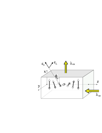
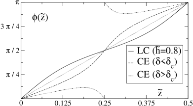
helical director structure, given by (where is the angle the director makes with the -axis), to one dominated by regions of slowly varying angles, separated by increasingly sharp twist walls [15]: see fig. 2.
At a critical , the walls become thermodynamically unstable and the director experiences periodic oscillations about which diminish with increasing . There are attendant contractions perpendicular to the stretch. The pitch shrinks affinely [11] with the matrix. In the small stretching limit (), the pitch varies as and the first reciprocal lattice vector goes as . Thus, the band structure changes upon extension because of two factors: the dilation of the reciprocal space and the change in the modulation character of the dielectric tensor along the pitch axis, . These changes can be very large.
Theory.—Maxwell’s equations yield [16]:
| (1) |
Consider normal incidence, along the axis. The magnetic field is transverse and exists wholly in the plane. We thus suppress the components in the inverse dielectric tensor, given by in its principal frame (oriented at angle to , see fig. 1), and is only .
We apply Bloch’s theorem to decompose into plane wave components [16], so that
| (2) |
where the unit vectors are , and , and the reciprocal lattice vector , for integer. This procedure yields a matrix equation that reduces to a dimensionless form: lengths transform according to , wave vectors go as , reciprocal lattice vectors , frequencies go as and where . This reduction is important for the proper interpretation of the shifts of band structure
Eq. (1) then assumes the form . thus determines the photonic band structure of a CLC. It depends on the reduced inverse dielectric tensor at arbitrary and thus angle :
| (3) |
where follows the notation of de Vries [8], and the are the Pauli spin matrices.
One can then show that in space, is given by
| (4) | |||||
| (5) |
where and are the Fourier coefficients of and , respectively: , and similarly.
The undeformed director angles are . On an -strain , accompanied by relaxation assumed to be uniform and determined by energy-minimisation, the principal frame orientation is given by [15]
| (6) |
where is the shape anisotropy of the polymers underlying the nematic phase. See fig. 2 for for various . From , one can easily obtain and , and thus, and .
Numerical diagonalisation of the matrix at a range of yields a dispersion relation , along with eigenvectors giving the character of each solution. In general, the eigenvectors are elliptically polarised inside the CLC medium, with semi-major and semi-minor axes corresponding at each point to the local principal axes of the dielectric tensor, and nearly circularly polarised in vacuo [8]. We take and a depressed value throughout, simply for readability.
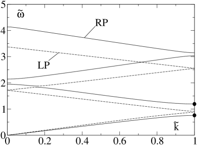
At small , the dispersion relation for an ideal CLC (i.e., ) is linear, corresponding to non-dispersive waves, with a simple effective refractive index , suggesting that both modes effectively experience the same, homogeneous medium at long wavelengths. This small behaviour is initially retained in the strain-modified band structures, see fig. 3.
At , the branch whose polarisation rotates in the same sense as the helix in vacuo develops the de Vries gap [8]. The eigenmodes of this branch at the zone boundary are linearly polarised inside the CLC medium. The lower band’s electric vector points along , the upper band’s perpendicularly to , in the plane. The other branch, however, cannot split analogously, since its polarisation in vacuo rotates in a sense opposite to the helix. This is qualitatively like the major gap in the distorted band structure, marked with dots at in fig. 3. Furthermore, no gaps are observed for , because band gaps are created only when degenerate energy states are linked by non-zero matrix elements. Since in the de Vries case, there are only two harmonic components of equal and opposite frequencies, only the matrix elements linking the two lowest energy states on either side of the first Brillouin zone boundary are non-vanishing.
We now stretch CE’s with for definiteness, which gives a [15]. Fig. 3 shows the dispersion relation for an elongation . Since the first Brillouin zone boundary is at , band gaps may occur at , for integer , with . This corresponds to a shift in colour and lasing frequency [11] toward the ultraviolet.
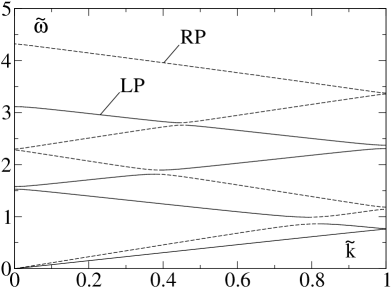
For , there is a qualitative change in the behaviour of the director, (see fig. 2), and thus a qualitative change in the band structure. Additionally, the scaling behaviour of changes [15] from , in the limit of small stretching (), to for , the classical exponent for isotropic CE’s. Fig. 4 shows the dispersion relation for a stretch .
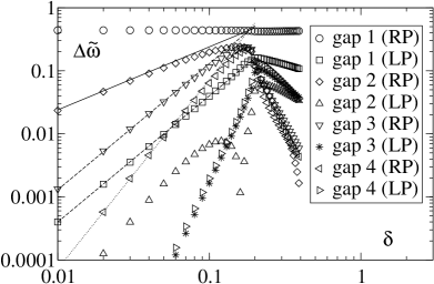
We now analyse the gap structures that open up in the stretched case, . The elastic strain, , is the perturbation parameter modifying the perfect helical structure. Whereas before, , and otherwise, we now have non-zero values for which scale as for and ; and . Applying degenerate perturbation theory, we eliminate all matrix elements in except for those linking the degenerate energy states, and predict that the gaps for the interesting polarisation in the de Vries case will scale with the magnitude of the off-diagonal elements, given by . The order (de Vries) gap will be approximately constant, the order gap (first new gap) will grow as , the order gap will grow as , and so on: see fig. 5. More precisely, at the order gap, , since . As a result, we also predict that the opposite polarisation will now have a non-zero gap that scales as . That tells us that a full photonic band gap will be created at as we perturb our helix by transverse elongation, and that its size will scale as , the size of the much smaller gap of opposite polarisation. See figs. 3 and 5.
Of experimental interest is the in vacuo wavelength, , of the light corresponding to a given on the dispersion relation, particularly at the gaps. The definitions below (2) give . Pitches typically give a band in the visible so the initial wavelengths are at , which allows us to write . Likewise the first order de Vries gap is given by . The higher order gaps of the same polarization will have widths of , where is a pre-factor of order unity that will depend on and . For example, the second order gap in a rubber with , , and , the gap will be . For , that implies a stop band for the light with a circular polarization of the same sense as the helix will be observed for to .
Finally, a note about oblique incidence in CE’s. By symmetry, we expect that the magnetic field must have the same magnitude at all points for a given , and only differ by a phase. That lets us generalize the vector for normal incidence, eq. (2), by and . Our preliminary findings indicate that for a constant , the stop bands shift upwards as we increase the angle of incidence from zero, which implies that refraction out of a normally incident beam path is forbidden for modes just above the stop band. That observation provides a mechanism to explain the spatial coherence of the light produced by dye-doped pumped lasers based on CLC’s and CE’s [10, 11].
Cholesteric Liquids.—We apply an external magnetic field along the direction. A CLC has an anisotropic susceptibility . The helix untwists (increasing the period) and coarsens [17] until the energy gain from aligning with the field balances the Frank penalty for deviations from the original structure. The coarsening of the director orientation is illustrated in fig. 2, with the -coordinate being reduced to by the lengthening period. At a critical field , where is the Frank twist elastic constant, the period diverges logarithmically as the entire sample aligns with the external field [17]. For typical cholesteric liquids with a pitch of , and [9]. Differences from the case of a CE under strain are detailed in [15].
The optical implications of coarsening were investigated by Meyer [18]. The Fourier coefficients describing the twist of the cholesteric liquid are found to scale just like the coefficients describing CE’s for . One can use the results for the CE case for a cholesteric liquid under the transformation . The dispersion relations are qualitatively the same as in fig. 3. The width and scaling of the gaps created resemble those of fig. 5, but with all effects ending abruptly at .
Conclusions.—An entirely new type of photonic material has been described and characterized. Not only is it self-assembling and easily available as large, defect-free single crystals, but it is highly deformable. Earlier descriptions [15, 17] of its modified periodic dielectric structure have been used as the basis for calculating its band structure. New gaps arise and their widths scale in a well-understood fashion with the stretch applied to the material or the strength of the external field. The midgap frequencies shift position by large amounts comparable
to their initial values.
We thank A Genack and P Palffy-Muhoray for introducing us to lasing in cholesterics, and acknowledge valuable discussions with EM Terentjev, Y Mao, H Finkelmann, ST Kim, W Stille, S Shiyanovskii, PD Haynes, PB Littlewood and S Johnson.
REFERENCES
- [1] S. John, Phys. Rev. Lett. 58, 2486 (1987).
- [2] M.D. Tocci, M. Scalora, M.J. Bloemer, J.P. Dowling and C.M. Bowden, Phys. Rev. A 53, 2799 (1996).
- [3] E. Yablonovitch and T.J. Gmitter, Phys. Rev. Lett. 63, 1950 (1989)
- [4] E. Ozbay, A. Abeyta, G. Tuttle, M. Tringides, R. Biswas, C.T. Chan, C.M. Soukoulis, K.M. Ho, Phys. Rev. B 50, 1945 (1994).
- [5] J.E Wijnhoven and W.L. Vos, Science 281, 802 (1998).
- [6] A. Urbas, Y. Fink and E.L. Thomas, Macromolecules 32, 4748 (1999).
- [7] M. Muller, R. Zentel, T. Maka, S.G. Romanov and C.M.S. Torres, Adv. Mater. 12, 1499 (2000).
- [8] H. de Vries, Acta Crystallogr. 4, 219 (1951).
- [9] P.G. de Gennes and J. Prost, The Physics of Liquid Crystals (Clarendon Press, Oxford, 1993).
- [10] V.I. Kopp, B. Fan, H.K.M. Vithana and A.Z. Genack, Opt. Lett. 23, 1709 (1998); B. Taheri and P. Palffy-Muhoray, ALCOM Symposium, Cuyahoga Falls, 1999.
- [11] P. Palffy-Muhoray, A. Munoz, B. Taheri, H. Finkelmann and S.T. Kim, Adv. Mat. (sub. 2001).
- [12] O. Painter, R.K. Lee, A. Scherer, A. Yariv, J.D. O’Brien, P.D. Dapkus and I. Kim, Science 284, 1819 (1999).
- [13] J.P. Dowling, M. Scalora, M.J. Bloemer and C.M. Bowden, J. Appl. Phys. 75, 1896 (1994).
- [14] S.T. Kim and H. Finkelmann, Macromol. Rapid Comm. (in press).
- [15] M. Warner, E.M. Terentjev, R.B. Meyer and Y. Mao, Phys. Rev. Lett. 85, 2320 (2000).
- [16] R.D. Meade, A.M. Rappe, K.D. Brommer, J.D. Joannopoulos and O.L. Alherhand, Phys. Rev. B 48, 8434 (1993).
- [17] R.B. Meyer, Appl. Phys. Lett. 12, 281 (1968); P.G. de Gennes, Solid State Comm. 6, 163 (1968).
- [18] S.G. Chou, L. Cheung and R.B. Meyer, Solid State Comm. 11, 277 (1972).