Dislocation nucleation and vacancy formation during high-speed deformation of fcc metals
J. Schiøtz,1 T. Leffers2 and B. N. Singh2
1 Center for Atomic-scale Materials Physics (CAMP) and Department of Physics, Technical University of Denmark, DK-2800 Kongens Lyngby, Denmark
2 Materials Research Department, Risø National Laboratory, DK-4000 Roskilde, Denmark
Abstract
Recently, a dislocation free deformation mechanism was proposed by Kiritani et al., based on a series of experiments where thin foils of fcc metals were deformed at very high strain rates. In the experimental study, they observed a large density of stacking fault tetrahedra, but very low dislocation densities in the foils after deformation. This was interpreted as evidence for a new dislocation-free deformation mechanism, resulting in a very high vacancy production rate.
In this paper we investigate this proposition using large-scale computer simulations of bulk and thin films of copper. To favour such a dislocation-free deformation mechanism, we have made dislocation nucleation very difficult by not introducing any potential dislocation sources in the initial configuration. Nevertheless, we observe the nucleation of dislocation loops, and the deformation is carried by dislocations. The dislocations are nucleated as single Shockley partials.
The large stresses required before dislocations are nucleated result in a very high dislocation density, and therefore in many inelastic interactions between the dislocations. These interactions create vacancies, and a very large vacancy concentration is quickly reached.
1 Introduction
In a recent paper, Kiritani et al. reported that a large number of vacancies were produced during high-speed heavy plastic deformation of thin foils of fcc metals (Kiritani et al. 1999). They observed a large density of stacking-fault tetrahedra but very low dislocation densities in the foils after deformation. As a possible explanation, they propose a dislocation-free deformation mechanism.
In this paper we use computer simulations to investigate, whether such a dislocation-free deformation mechanism becomes possible at very high strain rates, and we look for other possible explanations of the high rate of vacancy production. We have attempted to make the generation of dislocations as difficult as possible in order to favour such a dislocation-free deformation mechanism. We have therefore chosen to simulate systems that are initially dislocation free (i.e. without conventional dislocation sources such as Frank-Read sources). We have also chosen to simulate single crystals in order to avoid dislocation emission from grain boundaries. Simulations of high-speed deformation of polycrystalline (nanocrystalline) material have been reported elsewhere (Schiøtz et al. 1998, 1999, Van Swygenhoven and Caro 1998).
2 Simulation methods and setup
The simulations were performed using molecular dynamics. The interatomic interactions were described using the effective medium theory (Jacobsen et al. 1987, 1996) which gives a good description of the metals investigated here. The crystal is deformed at a constant strain rate, while keeping the stress in the transverse direction approximately constant, as described in details by Schiøtz et al. (1999). In all cases a strain rate of was used (versus approximately in the experiments). To keep the temperature of the system approximately constant during the simulation, Langevin dynamics are used, i.e. a friction and a fluctuating force are added to the equations of motion of the atoms (see e.g. Allen and Tildesley 1987). We use a timestep of 5 fs, safely below the value where the dynamics become unstable.
During the simulations, configurations were rapidly quenched and common neighbour analysis (Honeycutt and Andersen 1987, Faken and Jónsson 1994) was used to identify the local crystal structure. This was used to generate plots where all atoms except atoms at the dislocation cores were made invisible, allowing visualization of the dislocation structures.
Four different setups were used for the simulations.
2.1 System I.
The first system investigated was an fcc single crystal containing approximately 95 000 atoms. The system is approximately cubic with a side length of 105 Å. There are periodic boundary conditions along all three directions to emulate that the system is far from any surfaces. The crystal structure is perfect, apart from four randomly introduced vacancies. They were introduced in case the vacancies might participate in the proposed dislocation free deformation mechanism. The crystal is deformed along the [521] direction. This direction was chosen to avoid high-symmetry directions.
2.2 System II.
Similar to system I, but with free boundary conditions in the directions perpendicular to the pulling direction, i.e. the geometry is that of an infinite wire with square cross section.
2.3 System III.
A single fcc crystal with approximately 765 000 atoms. The system is approximately cubic with a side length of 210 Å. As in system I there are periodic boundary conditions in all three directions. The crystal is deformed along the [05] direction.
2.4 System IV.
As system III, but the periodic boundaries in one direction were replaced with free boundary conditions. This results in a “film” geometry, a thin film (thickness 210 Å) with free (512) surfaces, repeated infinitely in the two remaining directions. The film was deformed along the [05] direction.
As the preexisting vacancies in systems I and II did not participate in the deformation, no vacancies were introduced in the initial configuration of systems III and IV.
3 Results
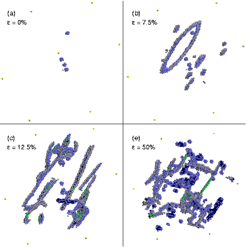
Figure 1 illustrates the deformation of System I. The same deformation mode is seen in system III and (with a small modification, see below) in system IV.
In figure 1(b) the first dislocation activity is observed in the form of a few homogeneously nucleated dislocation loops. The loops expand rapidly. Due to the periodic boundary conditions the dislocations cannot disappear from the sample. They will continue to move, causing significant plastic deformation.
After some dislocation activity has occurred, we observe the first creation of vacancies in figure 1(c). A “sausage-like” string of vacancies have appeared in the middle of the system. As the deformation proceeds, the string of vacancies is broken up by the dislocation activity, and the vacancies are dispersed into single vacancies and smaller clusters. At the same time, more vacancies are being generated.
3.1 Dislocation nucleation.

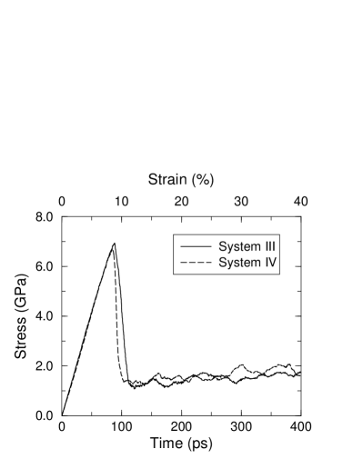
Figure 2 shows the stress versus time and strain for the simulations. It is clearly seen that the deformation falls in two parts, an elastic and a plastic regime. In the elastic regime (below ), no dislocations are present in the sample, and no plastic deformation is possible. As there are no dislocation sources, dislocations cannot be nucleated until the stress is close to the theoretical shear stress, where (111) planes can glide with respect to each other. At this point thermal fluctuations are enough to nucleate dislocations. This is seen in figure 1b. A number of loops have been nucleated almost simultaneously. The first one to be nucleated is clearly seen, but a number of emerging loops are seen as well.
The loops consist of a single Shockley partial dislocations, and are thus faulted loops. The second partial is not being nucleated. This is because the barrier for nucleating the second partial is almost as high as the barrier for nucleating the first partial, but by the time the first partial is nucleated, it screens the stress field. The trailing partials are thus not nucleated. It should also be noted that the stacking fault energy in copper is relatively low, and furthermore the stacking fault energy in the simulation is approximately a factor of two below the experimental value (Schiøtz and Carlsson 2000). For similar reasons, only Shockley partial dislocations are seen in simulations of the mechanical deformation of nanocrystalline metals (Schiøtz et al. 1999).
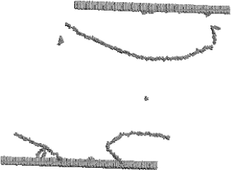
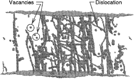
The behavior in system I and III are very similar, as they only differ by the size of the system. In system IV, where free surfaces are present, the dislocations are (perhaps not surprisingly) nucleated at the surfaces. Since the surfaces are defect-free, they are not good sources for dislocations, and the dislocations are nucleated only marginally earlier than in the bulk simulations (see fig. 2). The dislocations are again nucleated as single Shockley partials in the form of a faulted half-loop. When the loop reaches the opposite surface the result is two dislocations that extend from one surface to the other. Such dislocations cannot run out of the sample due to the periodic boundary conditions, and again a large dislocation density is the result. See fig. 3.
In system II dislocations are nucleated at the corners of the system. Again, the lack of defects prevents dislocation nucleation until a very high stress is reached, even though the lower atomic coordination at the corners allows dislocation nucleation at a stress that is approximately 25% lower than in the bulk and film configurations. Unlike the other geometries, there is nothing to prevent the dislocations from moving out of the sample at the opposite surface, and this is indeed what happens. Initially, two dislocations are nucleated approximately simultaneously on opposite corner. Just before the dislocations reach the opposite corner new dislocations are nucleated, perhaps due to the local heating caused by the moving dislocation. This repeats itself a few times until the stress has been reduced. After the brief surge of dislocation activity, the sample is again dislocation free and the stress can build up again (fig. 2). No evidence is seen for kinematic generation of new dislocations near the rapidly moving dislocation. This has previously been seen in simulations under similar conditions except the temperature was close to zero Kelvin (Schiøtz et al. 1995). The reason appears to be that phonon drag at the temperature of the simulations presented here (450K) prevents the dislocations from reaching the Rayleigh velocity.
3.2 Vacancy production.
After some dislocation activity vacancies appear in the simulation. The vacancies initially appear in the form of short strings of vacancies. A closer look at the simulation shows how the vacancy structure appears. Dislocation interactions have created dislocations where segments are on different glide planes. When these dislocations meet, it is possible that two segments of edge dislocation with opposite signs annihilate. If the dislocations are not on the same slip plane, but on adjacent slip planes, a string of vacancies or interstitials is generated. In the simulations interstitial generation by this mechanism is never observed, probably because the energy of a string of interstitials is so high that the colliding dislocations pass by each other instead of annihilating. The vacancy formation mechanism is further discussed elsewhere (Schiøtz et al. 2000).
4 Discussion
The simulations presented here demonstrate that even in a situation where the generation of dislocations has been made as difficult as possible, dislocation nucleation does occur before any dislocation-free deformation mechanism is activated. Once dislocations are nucleated, they carry the plastic deformation, and no evidence of a dislocation free deformation mechanism is seen neither in bulk nor in thin film simulations.
The high vacancy concentration seen experimentally (Kiritani et al. 1999) is reproduced in the simulations. The vacancies are created by dislocation–dislocation interactions, which raises the question “why are a similar concentration of vacancies not seen in ordinary deformation experiments?” After all, the same number of dislocations must pass through the sample to give the same final strain, regardless of the strain rate. However, the number of dislocation-dislocation interactions is proportional not only to the number of dislocations passing through the sample, but also to the average dislocation density. The dislocation density is likely to be significantly larger under high-speed deformation, partly because more dislocation sources may be activated by the higher stresses reached during the high-speed deformation, partly because new dislocations are nucleated from the dislocation sources before the previous ones have time to reach a dislocation sink.
The vacancy density observed in the simulations () is in excellent agreement with the observed densities (). To some extent this agreement is fortuitous, since the strain rate is much higher in the simulations than in the experiments, whereas the total strain is higher in the experiments. It is, however, important that the right order of magnitude is found for the vacancy density.
In the experiments presented by Kiritani et al. (1999) no (or very few) dislocations are seen in the sample after deformation — in constrast to the simulations, where a large dislocation density is seen (figure 3). However, the time scale of the experiment is much longer than the time scale of the simulations, giving ample time for the dislocations to disappear. It is clear that when the dislocation line goes from one surface to the other (as is the case of most of the dislocations in figure 3) they cannot simply move to the surface and disappear. In the reported experiments, the TEM micrographs were taken near the egde where the foils were torn apart since this is where the foil was sufficiently thin. In this case it must be assumed that the foil is wedge-shaped, and that the dislocations can leave the sample by moving to the edge where the foil broke. In in-situ TEM studies, where the foil is examined before it breaks (Kiritani 2000), the thinnest part of the film is examined. If there are no dislocation sources in this part of the film, the stress will increase until dslocations are nucleated at the surface. These dislocations will be accelerated to very high velocities and leave the region being studied by the TEM. They are not observed because of their high velocity. The phenomenon that dislocations are rapidly expelled from a region with a local stress concentration is well known from fracture mechanics, where a dislocation free zone (DFZ) is formed in front of the crack tip (Kobayashi and Ohr 1980, Chang and Ohr 1981, Ohr 1985). We propose that a similar DFZ is formed here, and that this explains why dislocations are not observed in the experiments.
Shimomura et al. (1999) have recently published simulations of high-speed deformation in Cu and Al (the interatomic potential used was not reported). They have used systems with 4000 atoms, and either full periodic boundary conditions (similar to system I) or with wire-symmetry (as system II). They report that the deformation occurs without dislocations, but by “tilting of atom rows”. However, this tilting is nucleated at one surface and proceeds through the specimen. Based on the published material, we are not able to see the difference between this mechanism and the propagation of a dislocation with screw character through the specimen.
In simulations of nanocrystalline metals a “dislocation-free” deformation mechanism is seen where the grain boundaries carry the deformation (Schiøtz et al. 1999, 1998). Such a mechanism can be ruled out in the experiments by Kiritani et al. (1999) as it only works when the density of grain boundaries is extremely high, i.e. at grain sizes below approximately 10 nm. Furthermore, no generation of vacancies is expected.
5 Conclusions
We have simulated high-speed deformation of copper in bulk and in thin films. In spite of not having included any dislocation sources in the initial configuration, dislocations are nucleated and the plastic deformation occur by the motion of dislocations. We thus find no evidence for the dislocation-free deformation mechanism proposed by Kiritani et al. (1999). Inelastic interactions between the dislocations results in the production of vacancies. After the deformation is complete, a very high vacancy density is seen, in agreement with the experimental observations. We propose that the reason why no dislocations are seen in the experiments is the formation of a “dislocation free zone” where the dislocations rapidly leave the part of the film where the stresses are largest.
Acknowledgments
We would like to thank Prof. Kiritani for fruitful discussions. The Center for Atomic-scale Materials Science (CAMP) is sponsored by the Danish National Research Foundation. This work was done as a collaboration between CAMP and the Engineering Science Center for Structural Characterization and Modelling of Materials at Materials Research Department, Risø. Parallel computer time was financed by the Danish Research Councils through grant no. 9501775. The authors are collaborating with the Academic Frontier Research Center for Ultra-high Speed Plastic Deformation at Hiroshima Institute of Technology.
References
References
- Allen and Tildesley (1987) Allen, M. P. and Tildesley, D. J., 1987, Computer simulation of liquids (Oxford: Claredon Press).
- Chang and Ohr (1981) Chang, S.-J. and Ohr, S. M., 1981, J. Appl. Phys., 52, 7174.
- Faken and Jónsson (1994) Faken, D. and Jónsson, H., 1994, Comput. Mater. Sci., 2, 279.
- Honeycutt and Andersen (1987) Honeycutt, J. and Andersen, H., 1987, J. Phys. Chem., 91, 4950.
- Jacobsen et al. (1987) Jacobsen, K. W., Nørskov, J. K., and Puska, M. J., 1987, Phys. Rev. B, 35, 7423.
- Jacobsen et al. (1996) Jacobsen, K. W., Stoltze, P., and Nørskov, J. K., 1996, Surf. Sci., 366, 394.
- Kiritani (2000) Kiritani, M., 2000, Plastic deformation of crystalline metals without dislocations, Presentation at the 3rd Workshop on High-Speed Deformation, Hiroshima.
- Kiritani et al. (1999) Kiritani, M., Satoh, Y., Kizuka, Y., Arakawa, K., Ogasawara, Y., Arai, S., and Shimomura, Y., 1999, Phil. Mag. Lett., 79, 797.
- Kobayashi and Ohr (1980) Kobayashi, S. and Ohr, S. M., 1980, Phil. Mag. A, 42, 763.
- Ohr (1985) Ohr, S. M., 1985, Mater. Sci. Eng., 72, 1.
- Schiøtz and Carlsson (2000) Schiøtz, J. and Carlsson, A. E., 2000, Phil. Mag. A, 80, 69.
- Schiøtz et al. (1998) Schiøtz, J., Di Tolla, F. D., and Jacobsen, K. W., 1998, Nature, 391, 561.
- Schiøtz et al. (1995) Schiøtz, J., Jacobsen, K. W., and Nielsen, O. H., 1995, Phil. Mag. Lett., 72, 245.
-
Schiøtz et al. (2000)
Schiøtz, J., Leffers, T., and Singh, B. N., 2000,
(submitted for publication).
URL http://arXiv.org/abs/cond-mat/0008336 - Schiøtz et al. (1999) Schiøtz, J., Vegge, T., Di Tolla, F. D., and Jacobsen, K. W., 1999, Phys. Rev. B, 60, 11971.
- Shimomura et al. (1999) Shimomura, Y., Sugio, K., and Kiritani, M., 1999, Comput. Mater. Sci., 14, 97.
- Van Swygenhoven and Caro (1998) Van Swygenhoven, H. and Caro, A., 1998, Phys. Rev. B, 58, 11246.