Angle-Resolved Spectroscopy of Electron-Electron Scattering in a 2D System
Abstract
Electron-beam propagation experiments have been used to determine the energy and angle dependence of electron-electron (ee) scattering a two-dimensional electron gas (2DEG) in a very direct manner by a new spectroscopy method. The experimental results are in good agreement with recent theories and provide direct evidence for the differences between ee-scattering in a 2DEG as compared with 3D systems. Most conspicuous is the increased importance of small-angle scattering in a 2D system, resulting in a reduced (but energy-dependent) broadening of the electron beam.
72.10.-d,72.20.Dp
The scattering characteristics of electrons in systems with reduced dimensions are expected to exhibit decisive differences with respect to the situation in the bulk. Theoretically, electron-electron (ee) scattering in two-dimensional (2D) systems was first considered in the early seventies [1]. Further numerical evaluations followed in the early eighties [2]. It was shown that the life-time of a non-equilibrium electron in a 2DEG is shorter by a factor of order compared to the three-dimensional (3D) case ( is the electron’s excess energy counted from the Fermi energy, ).
A reduction of the dimensionality induces much more drastic changes in the momentum transfer processes [3, 4, 5, 6, 7]. Two types of ee-collisions with nearly the same probability characterize scattering in 2D systems [3]: (i) Collisions of a non-equilibrium electron with momentum and excess energy with equilibrium electrons usually result in scattering of both electron by a small angle into states and leaving a hole (an empty place in Fermi distribution) in state , with . (ii) Collisions with electrons of nearly opposite momentum, : In this case, the electrons at and are scattered by a much larger angle, on average .
The details of the scattering behaviour can be visualized by the angular distribution function of the scattered electrons, , where the angle is measured with respect to [7]. By definition, is the probability that a non-equilibrium electron, [or hole for ], emerges in an interval after scattering. This function is shown for two different electron excess energies in Fig. 1. For comparison, we have also plotted the most commonly used approximation for for 3D systems, sometimes referred to as the Callaway Ansatz [, and independent of ]. For 3D systems is very smooth, exhibiting a broad distribution of electrons moving in forward direction and holes moving backwards. In the 2D case shows several distinct features. Most conspicuous is a very narrow distribution of electrons moving in forward direction.
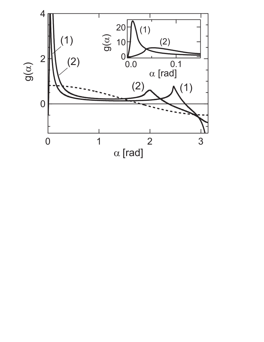
The height of this peak is determined by the small-angular processes of type (i); its width is determined by type (ii) processes and increases with energy according to . The type (ii) scattering events also cause a secondary peak at and a narrow hole dip of width at [7]. However, these effects occur in the backscattered direction and are quite small, so that they will be difficult to detect experimentally. For a comparison with experiments we therefore focus on angles (rad), where the small angular scattering peak should provide a clear token of specific 2D phenomena. Another intriguing feature of , which can be seen more clearly in the inset of Fig. 1, is a dip in forward direction for very small angles, with a width . This dip is caused by the conservation laws: The electron may give away its surplus energy to equilibrium partners only upon scattering by a finite angle. This effect, which was discussed earlier in Refs. [4, 8], also occurs in 3D systems. However, in 2D the amplitude of the dip is enhanced by a factor .
Up to now no direct experimental evidence for these 2D effects in ee-scattering has been demonstrated. Recently,
we published results indicating the dominance of small angle scattering in the propagation of an electron beam in a 2DEG indirectly [9]. Now, we have been able to extract directly. This experiment provides compelling evidence for the preponderance of small-angle scattering in 2D systems.
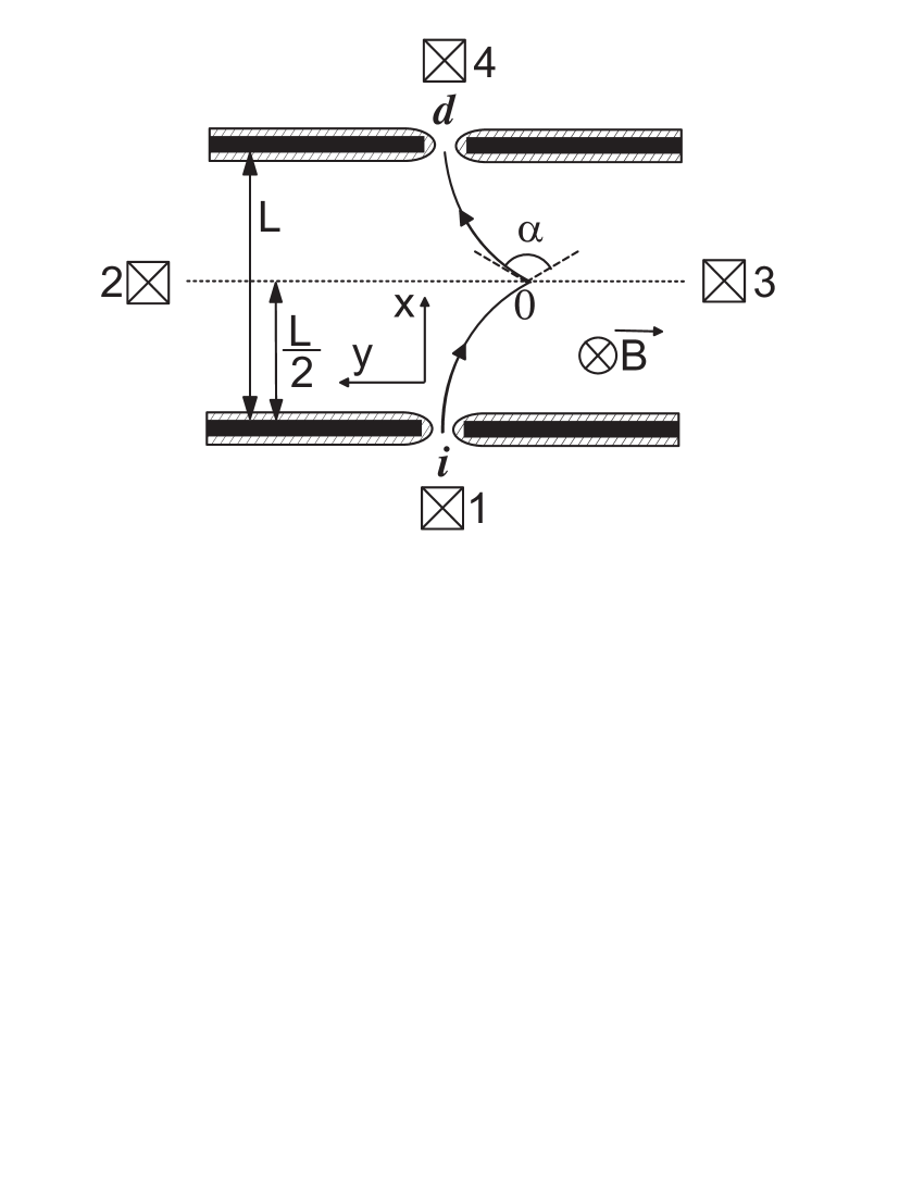
In the experiment, an electron beam injected into the 2DEG via an electrostatically defined quantum point-contact (QPC) i is detected by a second QPC d in a certain distance [10, 11], schematically shown in Fig. 2. When a magnetic field is applied perpendicular to the 2DEG plane, the injected beam is deflected and only scattered electrons can reach the detector QPC. At low electron excess energies one can neglect the energy dependence of the cyclotron radius . When the opening angle of the QPCs and [10] is sufficiently small i.e., , we have that for a given magnetic field the detector signal is determined only by one trajectory i.e., the signal results solely from electrons that were scattered in point across an angle (see Fig. 2). Thus, by changing the magnetic field we can directly measure the angular distribution function of scattered electrons in a wide range of angles .
As discussed above, will in general depend on the excess energy of the injected electrons. This is why we apply a differential measurement technique, which is equivalent to using mono-energetic electron beams. is controlled by adjusting the bias voltage applied between contacts 1 and 2. The non-local voltage drop measured between contacts 3 and 4 results from electrons have reached the detector QPC and charge the 2DEG area denoted . A small -modulation is added to the -bias. Although an electron beam injected via a QPC consists of electrons of all energies form up to , only the contribution of the high energy part of the beam to the signal can be detected by measuring
the signal with a lock-in at the same frequency as .
For the experiments, conventional Si-modulation doped GaAs-(Ga,Al)As heterosturctures were used, with a carrier concentration of cm-2 and an electron mobility of m2(V s)-1, which implies an impurity mean free path of m. A pair of QPCs, about m apart, were fabricated using split-gate technology. By applying a negative voltage to the gate contacts, the conductance of the QPCs () could be adjusted from several conducting modes into the tunneling regime (). Throughout all experiments injector and detector QPC were adjusted to to ensure narrow opening angles [10]. The injection dc-voltage, , was varied between 0 and 5 mV. The ac-modulation voltage was kept constant at V, so that . The sample was kept at a lattice temperature mK in a dilution refrigerator.
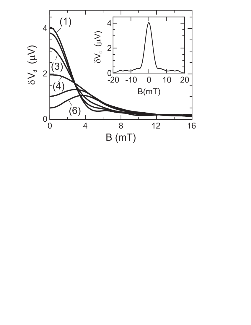
Fig. 3 displays some examples of the measured detector signal for various injection voltages as a function of magnetic field. The inset of Fig. 3 shows the measured signal at low injection energy meV, when the ee-scattering mean free path is much larger than and the electrons reach the detector QPC ballistically. From this we determine the characteristic opening angle [10] of injector and detector, . The detector signal is at maximum at zero magnetic field. With increasing injection energy ee-scattering becomes more important, leading to (i) a decrease of the signal of non-scattered electrons near , (ii) a broadening of the signal with and (iii) the appearance of a dip in the signal around for energies mV.
For further consideration we have to investigate how this experimental behaviour relates quantitatively to the expected 2D-scattering characteristics. Therefore, we describe the problem by a linearized Boltzmann equation in magnetic field,
| (1) |
where is the cyclotron frequency and is the linearized operator of the ee-collisions, which can be written as:
| (2) |
with . Integration of the collision integral kernel over energy yields the angular distribution function of the scattered electrons:
| (3) |
where is the angle between and , and refers to the electrons (holes) at , and mentioned above. If the probability for an electron to be scattered over a distance is small (i.e., ), Eq. 1 can be solved using pertubation theory on the collision integral. When we write the electron distribution function at the exit of the injector as , and consider only the first iteration of the collision integral, we can obtain an expression for the current through the detector QPC. For low injection energies , the detector signal can be written as:
| (4) | |||||
| (7) | |||||
Here , is the Fermi wave length and [ ] the angular emittance (acceptance) function of the injector (detector) QPC [10]. From this equation it is clear that can be obtained from the magnetic field dependence of .
When varies only slightly on the scale of the opening angle , a local approximation to the integrals in Eq.(4) can be made, yielding
| (8) |
The factor is given by for and for . Note that for small enough beam energies , a local approximation of Eq. (8) is invalid for scattering angles and Eq. (8) only yields a smoothed (by the emittance and acceptance functions) approximation of . The local approximation is also invalid for large scattering angles, .
However, it is possible to extend the range of validity for this one-collision approximation. This is because in all experiments we have that , implying that the probability for secondary ee-collisions is approximately an order of magnitude lower than that of the first one [5, 7, 12]. It turns out that a one-collision approximation is valid as long as , i.e. for a much wider range of parameters than the perturbation theory. Partial summation of the corresponding iteration series of Eq. (1), results in the following expression for :
| (9) |
which replaces in Eqs. (4) and (8). The exponential factor on the r.h.s. gives the probability for an electron to travel ballistically to a point of scattering, after which it reaches the detector without further collisions. In the local approximation of Eq. (8), can be interpreted as the length of the trajectory from the injector to point (see Fig. 2).
In order to compare the experimental data with theory, it is necessary to extract the contribution of scattered electrons, , from the observed signal . We have
| (10) |
Here, is the signal which would be observed in the absence of scattering, so that the second term on the r.h.s. of Eq. (10) is the contribution of electrons that reach the detector ballistically. Experimentally, can be obtained from the experiment at lowest injection energy mV. In this case and thus collisions can be neglected. For we use the expression for energy relaxation in a 2DEG obtained by Giuliani and Quinn [cf. Ref. [2], Eq. (13)].
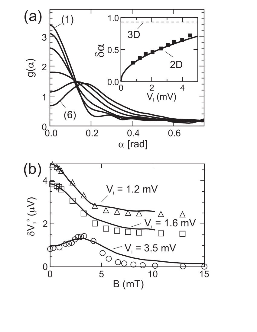
Fig. 4 (a) shows the angular distribution functions for various injector energies obtained from the experimental data in Fig. 3 using Eqs. (8), (9), and (10). The various clearly display the expected small-angle scattering behaviour. For small (curves (1) and (2), 0.8 and 1.2 mV, respectively) the observed peak width is only slightly larger than the point contact opening angle . As discussed above, in this limit the experimentally recovered is smoothed, and we cannot expect to observe the dip at very small angles.
The peak in broadens when the energy of the injected electrons is increased (curves 3-4). In the inset of Fig. 4 (a) the width of is displayed as a function of injection energy. It shows a clear square-root behaviour in contrast to 3D where is essentially energy-independent. The increase of with also directly implies that the small angle scattering observed by us can not be attributed with weak screening in 2D systems. In this case the scattering angle should actually decrease with excess energy.
When becomes larger than the QPC opening angle for higher , one can clearly observe the expected dip in forward direction [curves 5-6, Fig. 4 (a)]. The amplitude of the dip is much larger than would be the case for a 3D electron system.
As discussed above, the local approximation of Eq. (8) is not valid at small scattering angles . For these angles, is more precisely given by the integral equation:
| (11) | |||
| (12) |
where for and for . Here again we use as defined in Eq. (9); is the distance between injector and the crossing point (O) of electron trajectories injected at angle and detected at angle ; the integration in (11) has to be evaluated for all such that , while .
For comparison the results of Eq. (11) for various values of are presented together with experimental data for in Fig. 4 (b). As is evident from the figure, we find a gratiying agreement between theory (markers) and experiment (drawn curves), justifying the assumptions made in extracting from the experimental data.
The results presented in this paper demonstrate that a suitably performed electron-beam experiment can provide a wealth of detail on fundamental electron scattering processes, not only on the energy dissipation, but certainly also on momentum scattering. Note that by changing the detector gate voltage it is also be possible to analyze the scattered electrons’ energy dependence [11]. Combining this with -field dependent data as discussed in the present paper should enable a direct experimental determination of the collision integral kernel as a function of (detection energy), (injection energy, ) and angle . Although in the present paper we dealt solely with ee-collisions, one can investigate in the same way other scattering processes, e.g. electron-phonon [11] or electron-impurity collisions.
In conclusion, electron-beam experiments in the 2DEG of GaAs-(Ga,Al)As heterostructures demonstrate unambiguously the occurrence of small-angle ee-scattering. The scattering distribution function broadens with increasing electron energy, , and a pronounced dip occurs at small angles. The observations represent conclusive evidence for the manifestation of 2D density-of-states effects in the ee-scattering process.
ACKNOWLEDGMENTS
This work was supported in part by “Volkswagen-Stiftung” (Grant No.I/72531) and by the DFG (MO 771/1-2).
REFERENCES
- [1] A.V. Chaplik, Zh. eksp. teor. Fiz. 60 1845 (1971); C. Hodges, H. Smith, and J. Wilkins, Phys. Rev. B, 4, 302 (1971).
- [2] G.F. Guiliani, J.J. Quinn, Phys. Rev. B 26, 4421 (1982).
- [3] R.N. Gurzhi, A.I. Kopeliovich, and S.B. Rutkevich, Adv. Phys. 36, 221 (1987); R.N. Gurzhi, A.N. Kalinenko, and A.I. Kopeliovich, Phys. Low-Dim. Struct., 2 75 (1994).
- [4] R.N. Gurzhi, A.N. Kalinenko, A.I. Kopeliovich, Phys. Rev. B 52, 4744 (1995); R.N. Gurzhi, A.N. Kalinenko, A.I. Kopeliovich, Phys. Rev. Lett. 74, 3872 (1995).
- [5] R.N. Gurzhi, A.N. Kalinenko, A.I. Kopeliovich, Fiz. Nizk. Temp. 23, 58 (1997) [Low Temp. Phys. 23 44, (1997)].
- [6] B. Laikhtman, Phys. Rev. B 45, 1259 (1992).
- [7] H. Buhmann et al. Fiz. Nizk. Temp. 24, 978, (1998) [Low Temp. Phys. 24 737, (1998)].
- [8] D.R.S. Cumming, J.H. Davies, Appl. Phys. Lett. 69, 3363 (1996).
- [9] H. Predel et al. Phys. Rev. B 62, 2057 (2000).
- [10] L.W. Molenkamp et al. Phys. Rev. B 41, 1274 (1990).
- [11] U. Sivan, M. Heiblum, C.P. Umbach, Phys. Rev. Lett. 63, 992 (1989).
- [12] R.N. Gurzhi, A.N. Kalinenko, A.N. Kopeliovich, Surface Science 361/362, 497 (1996).