Generation and evolution of vortex-antivortex pairs in Bose-Einstein condensates
Abstract
We propose a method for generating and controlling a spatially separated vortex–antivortex pair in a Bose-Einstein condensate trapped in a toroidal potential. Our simulations of the time dependent Gross-Pitaevskii equation show that in toroidal condensates vortex dynamics are different from the dynamics in the homogeneous case. Our numerical results agree well with analytical calculations using the image method. Our proposal offers an effective example of coherent generation and control of vortex dynamics in atomic condensates.
pacs:
03.75.Fi, 32.80.Pj, 03.75.-bI Introduction
Quantum liquids and gases are an excellent environment for studies of solitons and topological quantum structures such as vortices. Studies of superfluidity and vorticity have been done mostly in He II [1]. Due to the high density and strong interactions the theoretical studies give usually only a qualitative agreement with experiments. Moreover, the size of the vortex core is very small in He II, typically Å. The situation is drastically different for atomic Bose-Einstein condensates [2]. These many-body systems are dilute and weakly interacting, and as a result a quantitative agreement between theory and experiments can often be found. Also, the expected size of a vortex core is fairly large, , making detailed experimental studies possible.
Several theoretical approaches have been suggested for the generation of vortices in condensates, see e.g. Refs. [3, 4, 5, 6, 7, 8, 9, 10]. Among them, the stirring of a condensate with a blue-detuned laser in a single component [11], and the coherent interconversion between the two components of a binary condensate [12] have been successfully implemented. In addition, the creation of vortex rings after the decay of a dark soliton has been recently reported [13]. These vortices carry one quantum of circulation each, and they form stable, geometric patterns. However, the success in controlling atomic condensates suggests that one could create also non-equilibrium situations to investigate dynamics of vortices, and in particular, vortex collisions. Alternatively, a vortex can be generated through the “phase-imprinting” method [7]. This approach has been successfully used to generate solitons in condensates [14].
Here we propose how to create and control a pair of spatially separated vortices of opposite circulation via controlled decay of dynamically unstable solitons in a toroidal trapped condensate. Due to the toroidal geometry and the employed technique for the creation of the vortices, the dynamics and circulation of the generated vortices are correlated, even when they are generated at well-separated locations.
In homogeneous condensates and in absence of dissipation a vortex–antivortex pair moves as a whole through the fluid [1]. Such behavior can be, however, substantially modified in the case of trapped condensates. In particular, for the case of stiff potentials the vortex dynamics is altered by the constraint of vanishing normal velocity field at the boundaries [15]. We show how vortex–antivortex dynamics in toroidal geometries become different from the equivalent dynamics in a homogeneous (not trapped) condensate.
We propose a combination of condensate splitting, phase imprinting, and subsequent merging of separated parts into a toroidal condensate, which leads to a very controlled mechanism of vortex creation. We describe the details of our proposal and numerical solution of the relevant Gross-Pitaevskii equation in Sec. II. In Sec. III we apply the method of images to explain the vortex dynamics and we give some concluding remarks in Sec. IV
II Vortex creation and dynamics numerically
We assume initially a condensate trapped in a Gaussian optical trap. By shaking the trap rapidly we split the condensate into two spatially separated parts [16]. First we slowly increase the amplitude of the periodic shaking along the chosen -axis [17]. The effective potential evolves smoothly from the Gaussian well into a trap with two separated minima; this is the time-averaged potential. The condensate follows adiabatically the changes of the time-averaged potential, splitting into two parts (Fig. 1). By adding a similar process along the -axis the time-averaged trapping potential evolves towards a torus. Thus the two separated condensate parts combine eventually into a torus. Before merging the two halves, we imprint on one of them (with a strongly detuned laser field [7]) a change of phase of the wavefunction, .
At sufficiently low temperatures, the system is well described by the corresponding Gross-Pitaevskii equation
| (1) |
Here is the condensate wavefunction, is the trap potential [17] (not the time-averaged one), is the number of atoms and , where is the -wave scattering length and is the atomic mass. In all simulations we have assumed a sodium condensate ( nm) with the particle number . The width of the trap in - and -directions was m and its size in the -direction m. The trap depth was set to . In our simulations the duration of each shaking stage was typically 50 ms. The creation of the torus can be seen in the first steps of Fig. 1. With the chosen parameters the trap ground state energy in -direction is considerably larger than the mean field energy at the toroidal trap ( is the atomic density). This fact allows us to restrict ourselves to a two–dimensional geometry.
The coherence time for the applied phase shift depends on the details of the shaking. If we express the wavefunction as and assume the Thomas-Fermi limit, i.e., ignore terms due to kinetic energy in Eq. (1), we obtain (assuming that changes sufficiently slowly)
| (2) |
Since in the Thomas-Fermi limit the right-hand side of Eq. (2) becomes independent of , the phase evolution is identical everywhere. During the time between applying the phase shift and the merging into a torus, the phase has changed by a constant amount over the condensate halves and thus there will be a discontinuity in the phase across the merging points, corresponding to the applied phase. If, on the other hand, the condensate exhibits sloshing, the kinetic energy term makes the phase evolution -dependent and the applied phase shift loses its meaning. Even a small asymmetry between the two parts is then enough to mask the applied phase shift on the time-scale of ms, which in effect leads to a total loss of the control of the vortex production. In our simulations the density distribution followed the Thomas-Fermi limit closely and, therefore, the phase evolution was almost identical everywhere.
When the phase-shifted condensate parts form a torus, the discontinuity in phase is quickly transformed into a dark soliton, since the system can adapt to the phase discontinuity only by reducing its density. In general, such a kink-like state in a trapped condensate is dynamically stable if the mean-field energy is roughly smaller than the characteristic trap energy in the direction given by the soliton front [18], which in our case corresponds to the typical energy of the trap in the radial direction. With the parameters from our setup [17] and cm-3, this condition is violated. Under such conditions the soliton front undergoes snake instabilities which can eventually decay into vortex-antivortex pairs (or vortex rings in 3D configurations), see e.g. [10, 18, 19, 20, 21, 22]. This process has been experimentally observed in non-linear optics [23], as well as, very recently, in matter waves [13]. Since the front perturbation with a wavevector , where is the healing length, will grow fastest [18], the distance between the generated vortices is expected to be about . If the normal modes are dynamically stable, i.e., if the torus is narrower than about the soliton is dynamically stable.
The depth of the soliton depends on the size of the phase discontinuity. It must be large enough for vortex generation. Otherwise the resulting soliton can decay into other excitations, or even remain stable. For example, a phase shift did not lead to generation of vortices in our simulations. Due to the degeneracy of the phase, the phase shift corresponds to the largest possible discontinuity. But one should note that the direction of the phase gradient over the discontinuity affects the subsequent evolution. If the phase difference is equal to , the degeneracy makes the direction of the gradient ambiguous. In our simulations the motion of vortices was initially indeterminate and thus very sensitive to small disturbances, when . For (as in Fig. 1), however, we obtain a much more predictable behavior. Due to symmetry, the mirror image of this situation is obtained with (the lower vortex moves clockwise in the beginning, and the upper one counterclockwise in Fig. 1).
In our simulations each soliton decays into a pair of vortices of opposite circulation. However, one of the vortices, located close to the edge of the condensate, has a very short lifetime, and decays within a few ms at the edge. The survival of only one vortex per soliton is not surprising, considering that , where is the width of the torus. For wider torii, i. e., longer solitons, our simulations show a decay of each soliton into many vortex-antivortex pairs, as expected [20]. Similar behaviour has been reported in simulations of condensates in rectangular boxes [24]. In our situation the condensate wave function remains symmetric with respect to reflection to the horizontal axis (see Fig. 1). This symmetry leads to correlations between vortex production at the two phase discontinuities, located on opposite sides of the torus. We are always left with two vortices (one vortex per soliton) of opposite circulations. These vortices have also opposite vertical and equal horizontal components of the velocity, and they are therefore automatically set on a collision course. This reflects the conservation of angular momentum (we have verified that the shaking process or the adiabatic merging of the separated condensate parts do not bring any extra angular momentum into the system)
Figure 1 shows the time evolution obtained from numerical simulations. The created vortices bounce from each other when they approach. This process repeats itself if we continue simulations beyond ms. In a nondissipative homogeneous system two vortices of opposite circulation separated by a distance greater than the healing length move parallel, since each vortex will move with the velocity of the other one[1]. Clearly, the vortex dynamics in a torus trap is more complex and completely different. It can be understood with the help of the images method.
III Images method
The images method has been recently successfully employed to describe both a single vortex[25], and vortex arrays dynamics in circular 2D traps [26]. We consider in the following a stiff torus (with infinitely high and stiff walls), i.e. we neglect the influence of the inhomogeneous trapping potential on the vortex dynamics [27, 28]. Additionally, we assume that the distance between the vortices is greater than the size of the vortex cores. In absence of friction the vortex velocity equals the superfluid velocity at the vortex position. Such a velocity field, which is induced by the presence of the vortices, has to fulfill the constraint of vanishing normal component at the torus boundaries. To fulfill this constraint it is enough to consider for each vortex an infinite number of fictitious image vortices, each with appropriate position and circulation. Each vortex, either real or image, contributes to the superfluid velocity field by , where and refer to its position and circulation, respectively.
Let us consider the case of a torus with an inner radius , an outer radius , and one vortex with circulation located at (in a frame centered at the origin of the torus). In order to cancel the normal component of the superfluid velocity on the boundaries, we have to consider two different families of image vortices. For the first family, an image vortex is placed at with circulation as well as one image vortex with circulation at the origin [29]. The image vortex at will induce a velocity component normal on the outer circle, so in addition we need an image vortex at with circulation . In turn this image will induce some normal component on the inner circle, so two more image vortices are required: one at with circulation the other one at the origin with circulation and so on and so forth. For the second family, one considers an image vortex at with circulation . This image vortex gives a normal component of the velocity on the inner circle so we need in addition one image vortex at with circulation as well as one image vortex at the origin with circulation . For this we require another image vortex at with circulation and so on. For the second real vortex in the torus we have to repeat the same formalism to get an image configuration, which ensures that the boundary condition is fulfilled.
That way we can express the total superfluid velocity field in the torus (for arbitrary circulations), in particular the velocity at the locations of the real vortices as a function of their mutual positions. Since the latter equals the vortex velocity we get the following first order equations for the vortex positions that can be easily computed
| (3) | |||||
| (4) | |||||
| (5) |
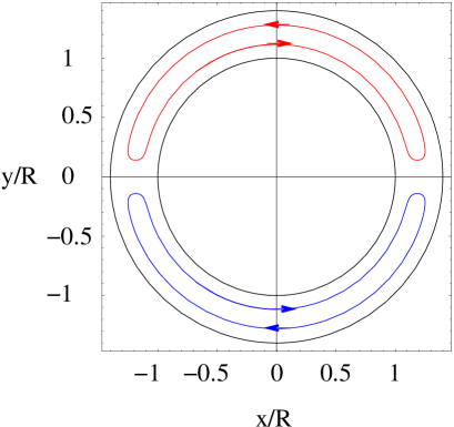
where indicates a term equal to the previous one but interchanging and . The results obtained with the image method are presented in Fig. 2. As initial conditions we take two vortices located on opposite parts of the torus and displaced symmetrically from the central point between the torus boundaries. For the sake of clarity our initial conditions have been chosen such that the vortex trajectories are wider, i.e., they explore more space between the torus boundaries than in the numerical simulation from Fig. 1. But with appropriate initial vortex positions one can achieve a nearly perfect agreement with simulations of Eq. (1) concerning the shape of the trajectories, and the period of their oscillations ( ms).
IV Conclusions
So far, we have assumed that the condensate is at zero temperature, i.e., we have used Gross-Pitaevskii equation (1) to model the condensate, neglecting any dissipation. The presence of non-condensate atoms is expected to result in dissipative Magnus forces and vortex decay. But experimental studies [11] so far show that a realistic time scale for vortex decay is a few seconds, which is longer than the time scale of our scenario. We tested the stability of our system by adding a small, constant imaginary term into Eq. (1). It did not modify the reported behavior unless the magnitude of the term was too strong to be considered a perturbation. Nevertheless, the problem of the effects of dissipation in our model is very challenging. The presence of dissipation might cause the vortex-antivortex pair either to collide with the trapping boundaries, or to mutually annihilate.
Another complication arises from the fact that currently the spatial resolution of the measurement of the condensate density profile is limited. Usually this problem is avoided by letting the condensate expand rapidly by removing the trapping potential. In a quasi-2D traps the optical depth will be an issue. Therefore some other detection scheme, such as matter wave interference [7, 32, 33, 34, 35], may have to be considered.
Summarizing, we have presented a method for creating vortices in a toroidal geometry in a controllable way. This method allows for the analysis of the interaction of vortices in such a geometry, which is significantly modified by the geometry of the trapping potential. The realm of possible phenomena that can be generated and controlled by merging the split condensate parts into a torus is not by any means limited by those discussed here, e.g. if we form the torus rapidly, other excitations are also created, which interact with the vortices and affect their dynamics.
In the analytical estimation of the vortex orbits we have neglected for simplicity the effects of the inhomogeneity of the trapping potential. Such inhomogeneity will result in an additional contribution to the velocity of the vortex in the direction perpendicular to the density gradient, as discussed in Ref. [28] (a detailed analysis will be the subject of a later publication). On the other hand, our calculations have been constrained to quasi-2D traps. Very recently the issue of lower dimensional BEC has been subject of great interest. In particular 2D (and even 1D) condensates have been experimentally observed [30, 31]. Therefore the situation considered in the present paper is experimentally justified and feasible. However, the analysis of 3D geometries constitutes a challenging problem. We have made some short simulations to study the dynamics of vortex-antivortex (line) interactions in a 3D pipe geometry. The results we obtain are very similar to those presented here. In a proper 3D geometry, the solitons decay into vortex rings, as observed very recently in the case of cylindrical traps [13]. The propagation, deformation and interaction of vortex rings will be the topic for future studies.
We thank M. Lewenstein, G. Shlyapnikov and M. Baranov for discussions. We acknowledge support of the Academy of Finland (project 43336), Center for Scientific Computing (CSC), and Deutsche Forschungsgemeinschaft (SFB 407). J.-P. M. is supported by the National Graduate School on Modern Optics and Photonics.
REFERENCES
- [1] R. J. Donnelly, Quantized vortices in Helium II, (CUP, Cambridge, 1991).
- [2] M. H. Anderson et al., Science 269, 198 (1995); C. C. Bradley et al., Phys. Rev. Lett. 75, 1687 (1995); K. B. Davis et al., Phys. Rev. Lett. 75, 3969 (1995).
- [3] K.-P. Martzlin et al., Phys. Rev. Lett. 79, 4728 (1997); K.-P. Martzlin and W. Zhang, Phys. Rev. A 57, 3801 (1998); ibid, 4761 (1998).
- [4] R. Dum et al., Phys. Rev. Lett. 80, 2972 (1998).
- [5] B. Jackson et al., Phys. Rev. Lett. 80, 3903 (1998).
- [6] B. M. Caradoc-Davies et al., Phys. Rev. Lett. 83, 895 (1999).
- [7] Ł. Dobrek et al., Phys. Rev. A 60, R3381 (1999).
- [8] J. Williams and M. Holland, Nature 401, 568 (1999).
- [9] D. L. Feder et al., Phys. Rev. A 61, 011601 (2000).
- [10] D. L. Feder et al., Phys. Rev. A 62, 053606 (2000).
- [11] K. W. Madison et al., Phys. Rev. Lett. 84, 806 (2000); J. Mod. Optics 47, 2715 (2000); cond-mat/0101051.
- [12] M. R. Matthews et al., Phys. Rev. Lett. 83, 2498 (1999).
- [13] B. P. Anderson et al., cond-mat/0012444.
- [14] S. Burger et al., Phys. Rev. Lett. 83, 5198 (1999); J. Denschlag et al., Science 287, 97 (2000).
- [15] A. L. Fetter, Phys. Rev. A. 138, 429 (1965).
- [16] R. Dum et al., Phys. Rev. Lett. 80, 3899 (1998).
- [17] The trap potential is , where K, m. We shake it by setting and for , and for , and and for . Here m, kHz, ms.
- [18] A. E. Muryshev et al., Phys. Rev. A 60, R2665 (1999).
- [19] E. A. Kuznetsov and S. K. Turitsyn, Sov. Phys. JETP 67, 1583 (1988).
- [20] C. Josserand and Y. Pomeau, Europhys. Lett. 30, 43 (1995).
- [21] Y. S. Kivshar and B. Luther-Davies, Phys. Rep. 298, 81 (1998).
- [22] J. Brand and W. Reinhardt, J. Phys. B 34, L113 (2001).
- [23] V. Tikhonenko et al., Opt. Lett. 21, 1129 (1996).
- [24] L. D. Carr et al., cond-mat/0004287.
- [25] P. O. Fedichev and G. V. Shlyapnikov, Phys. Rev. A 60, R1779 (1999).
- [26] M. Guilleumas and R. Graham, cond-mat/0012294; P. O. Fedichev and A. E. Muryshev, cond-mat/0004264.
- [27] B. Y. Rubinstein and L. M. Pismen, Physica D 78, 1 (1994).
- [28] A. A. Svidzinsky and A. L. Fetter, Phys. Rev. A 62, 063617 (2000).
- [29] P. G. Saffman, Vortex Dynamics, (Cambridge University Press, 1992).
- [30] A. I. Safonov et al., Phys. Rev. Lett. 81, 4545 (1998).
- [31] A. Görlitz et al., cond-mat/0104549.
- [32] E. L. Bolda and D. F. Walls, Phys. Rev. Lett. 81, 5477 (1998).
- [33] J. Tempere and J. T. Devreese, Solid State Commun. 108, 993 (1998).
- [34] Y. Castin and R. Dum, Eur. Phys. J. D 7, 399 (1999).
- [35] F. Chevy, K. W. Madison, V. Bretin, and J. Dalibard, cond-mat/0104545.